NOMENCLATURE
- r
vector of the rocket position
- v
rocket velocity
- Γ
flight path angle
- rT
vector of the target position
- xT, yT, hT
coordinates of the target
- xi, yi, hi, Vi
nominal trajectory coordinates and velocity at the sampling intervals
 $\begin{array}{l} x({{\hat x}_i}),\,y({{\hat x}_i})\\
h({{\hat x}_i}),V({{\hat x}_i}) \end{array}$
nominal trajectory coordinates and velocity at the estimated down range position
- γi, χi
nominal trajectory flight path angles at the sampling intervals
- γc, χc
correlated (demanded) flight path angles
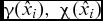
- $\gamma ({\hat x_i}),\;\chi ({\hat x_i})$
nominal trajectory flight path angles at the estimated down range position
- $\frac{{\partial \,\boldsymbol{r}}}{{\partial \,{\boldsymbol{r}_i}}}$
partial derivatives of the rocket range relative to the rocket position
- $\frac{{\partial \,\boldsymbol{r}}}{{\partial \,{\boldsymbol{v}_i}}}$
partial derivatives of the rocket range relative to the rocket velocity
- $\frac{{\partial \,\boldsymbol{r}}}{{\partial \,{\boldsymbol{\Gamma }_c}}}$
partial derivatives of the rocket range relative to the rocket flight path angles
- $\frac{{\partial \,\boldsymbol{r}}}{{\partial \,{t_i}}}$
partial derivatives of the rocket range relative to the time
- Δri
difference between the rocket actual position and the position on the nominal trajectory
- Δvi
difference between the rocket actual velocity and the nominal velocity
- ΔΓc
difference between the rocket required flight path angle and the nominal flight path angles
- Δti
error in time measurements
- $\frac{{\partial \,{\boldsymbol{\Gamma }_c}}}{{\partial \,{\boldsymbol{r}_i}}}$
partial derivatives of the rocket flight path angles relative to the rocket position
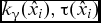
- ${k_\gamma }({\hat x_i}),\tau ({\hat x_i})$
gain and time constant of the flight path steering guidance loop
- azd, ayd
demanded normal acceleration
- az, ay
realised normal acceleration
- vne, ves
kinematic velocity relative to the Earth in navigation and spherical axis system
- fn, fs, fb
specific force in navigation, spherical and body axis system
- $\boldsymbol{\omega }_{ie}^n,\;\boldsymbol{\omega }_{i\,e}^s$
angular rate of the Earth relative to the inertial axis system in navigation and spherical axis system
- $\boldsymbol{\omega }_{en}^n$
angular rate of the navigation axis system relative to the Earth in navigation axis system
- $\boldsymbol{\omega }_{e\,s}^s$
angular rate of the spherical axis system relative to the Earth in spherical axis system
- $\boldsymbol{\omega }_{i\,e}^e$
angular rate of the Earth relative to the inertial axis system in Earth axis system
- $\boldsymbol{\omega }_{s\,b}^b$
angular rate of the body relative to spherical axis system
- $( {\boldsymbol{\omega }_{s\,b}^b \times } )$
skew-symmetric matrix
- $\boldsymbol{\omega }_{i\,b}^b$
angular rate of the body relative to the inertial axis system in body axis system
- $\boldsymbol{\omega }_{0s}^s$
angular rate of the spherical axis system relative to the basic axis system in body axis system
- Ω
angular rate of the Earth
- Cse
transformation matrix from Earth axis system to spherical axis system
- Csb(ψ, θ, ϕ)
transformation matrix from body to spherical axis system
- gs
gravity acceleration matrix in spherical axis system
- gnl, gls
gravity in navigation and spherical axis system
- g(h), g 0(φ)
gravity acceleration in function of altitude and on Earth's surface
- A 0
azimuth of the base axis system
- σy, σx
range and deviation angles in spherical axis system
- v xs, v y s, v zs
components of kinematic velocity in spherical axis system
- h
altitude
- φ
latitude
- x, y, h
coordinate of missile position in spherical axis system
- R 0
radius of the Earth
- facc
specific force matrix measured by accelerometers
- ${\boldsymbol{\omega }_{{\rm{r}}{\rm{.g}}}}$
angular rates matrix measured by rate gyros
- S
scale factor
- B
residual fixed bias
- n
random bias error
- w
noise
- N(asr, σ(a))
normal Gaussian distribution low
- FN
nominal thrust
- σ(F)
standard deviation of thrust
- εF
thrust eccentricity
- σ(εF)
standard deviation of thrust eccentricity
- σw
standard deviation of wind





1.0 INTRODUCTION
One of the basic requirements for the direct and indirect fire of projectile and rockets is increase of the range. However, as the range of a projectile or rocket increases the delivery accuracy deteriorates. A number of disturbances can cause rounds of the direct and indirect fire of projectile to miss an intended target. These disturbances include manufacturing inaccuracies of the gun tube, launcher, propellant and projectile, atmospheric condition, firing platform motion and aiming errors. Influences of some disturbances, such as thrust misalignments and asymmetric aerodynamic, are minimised by the rocket's spinning. However, wind, total impulse variations, launcher interactions, drag and atmospheric density variations still have a significant influence on the impact points accuracy(Reference Gantmakher and Levin1).
Reduction of the dispersion is achieved by adding a relatively inexpensive flight control system based on low-cost, small, rugged, micro-electromechanical sensors. There are two types of the control systems. One design concept is based on a lateral pulse jets system, and the second one is related to a set of controllable canards. Both control systems are located near the nose of the projectile. A control system requires an efficient guidance algorithm, which is usually based on estimated parameters of the projectile trajectory. An inertial navigation system (INS), which is composed of an inertial measurement unit (IMU) and a strap-down navigation algorithm, is usually used for trajectory estimation. The inertial measurement unit is composed of micro-electromechanical gyros and accelerometers fixed to the IMU body.
The US Extended Range Multiple Launch Rocket System (MLRS) program was initiated to increase the range of the rocket from 32km to 45km. The circular error probable (CEP) at a range of 45km is approximately double the CEP at a range of 32km. This increase of the dispersion requires the increase of the number of the rockets necessary to hit the target. In order to minimise the influence of disturbances on the impact accuracy, an extensive study was oriented to the development of a cost-effective guidance and control package which can be added to the rockets. The new Guided Multiple Launch Rocket System (GMLRS) with added cost-effective guidance and control package can defeat the target at ranges up to 70km with significantly fewer rounds. The rocket guidance system consists of an IMU, four independent electro-mechanically actuated canards, a Global Position System (GPS), a thermal battery, a guidance computer and power supply electronics. The guidance of these rockets was based on the Flight Path Steering (FPS) and Instantaneous Impact Point (IIP). FPS was used until apogee with a constant rate of flight path angle. At apogee, the missile switched to IIP guidance which predicts the point of impact. The warhead with a guidance and control system was joined to the motor section by a roll bearing. Roll decoupling of the forward section was required to maintain roll control of the guidance section in order to enable accurate inertial navigation(Reference Gamble and Jenkins2).
Analysis of the possibilities to use a lateral pulse jet control for dispersion improvement has been investigated by Harkins and Brown(Reference Harkins and Brown3). The set of lateral pulse jets was used to eliminate the lateral angular rate of the projectile just after the projectile left the launcher. Dispersion reduction of a direct fire rocket controlled by lateral pulse jets was analysed by Costello and Jitpraphai(Reference Jitpraphai and Costello4). The six-degree-of-freedom (6DoF) mathematical model was used in projectile flight dynamic modelling. The trajectory tracking flight control system compares the measured position of the projectile with commanded trajectory to generate a position error vector in the inertial frame axis system. Position and orientation sensor feedback is assumed to be perfect, that is, not corrupted by noise, bias or cross-axis sensitivity. It was shown that dispersion reduction is a strong function of the number of pulse jets and pulse jets impulse.
Impact point dispersion of the artillery rockets with pulse jets control system was studied by Pavkovic(Reference Pavkovic, Pavic and Cuk5). Reference ballistic trajectory of the artillery rockets was calculated before start of the launching sequence, taking into account measured atmospheric parameters (pressure, temperature and wind). Guidance signal was based on differences between actual and reference trajectory. Optimisation of the control logic was done in order to obtain a satisfactory performance with the minimum number and intensity of control pulses. It was assumed that the estimation of the rocket position was obtained by strap-down inertial navigation system. Measurements of the accelerometers and rate gyros were assumed to be perfect without noise, bias and cross-axis sensitivity. There was no analysis of the strap-down navigation algorithm and analysis of the influence of the measurement errors to the trajectory estimation.
The pulse jet control scheme is inherently discontinuous and can be only applied at a discrete number of points, and there is also limitation in the number of the impulses. Canard control is continuous and can be applied for the full flight duration. This type of the control can provide better accuracy and reduction of impact point dispersion.
Model predictive control of a direct fire projectile equipped with canards was investigated by Ollerenshaw(Reference Ollerenshaw and Costello6). The projectile configuration considered in the paper is fin stabilised and the fins are slightly canted to provide moderate roll rates during flight. The control law uses an approximate closed-form solution of projectile motion to predict the states of the projectile over a set of distances, known as the prediction horizon. Control of the projectile is based on minimising the estimated error of future states. It is assumed that sensor feedback is provided by an onboard IMU.
One of the published GMLRS guidance laws is based on the idea that the control system eliminates the differences between measured and prescribed values of the velocity vector angles and of the accelerations in the lateral directions of the rocket(Reference Gregoriou7). The prescribed values are obtained from the calculation of the nominal trajectory for a required range. In order to alleviate influence of total impulse deviation for the rockets with no thrust-termination mechanism, the correction of the prescribed flight path angle is defined empirically by trial and error. The proposed guidance law is not efficient because it is necessary to know disturbances in advance in order to determine the correction of the flight path angle in function of time.
The correlated velocity and velocity-to-be-gained guidance concept of the ballistic missile was analysed in detail by Siouris(Reference Siouris8). Correlated velocity is determined from a known target position and estimated missile position by a strap-down inertial navigation system. The difference between correlated and missile velocity defines velocity-to-be-gained which is used to control the missile. One type of this guidance system is Q guidance, which is based on Q matrix whose elements consist of directional derivatives. Velocity to be gained is determined by integration of the Q matrix in the feedback. This guidance system requires missile engine cut-off when the missile velocity becomes equal to the correlated velocity.
All guidance systems of the guided artillery rockets and ballistic missiles are based on the estimated parameters of the actual trajectory. Estimation of the trajectory is based on a strap-down navigation system and GPS receivers. The strap-down navigation system is composed of IMU and the navigation algorithm(Reference Rogers9,Reference Titterton and Weston10) . The mathematical model of IMU accelerometers and rate gyros measurements errors include scale factor error, bias and noise.
The purpose of this paper is to develop a flight path steering algorithm for artillery rockets whose entire trajectory is in dense layers of atmosphere. The task of the guidance law is to minimise the influence of the atmospheric disturbances and thrust eccentricity without possibility to control the magnitude of the velocity by solid rocket motor burn-out.
The published guidance laws for the artillery rockets are based on the spatial distance between real and reference trajectory.
Beside compensation of deviation of real from reference trajectory in the plane normal to the trajectory, the advance of flight path steering guidance law, developed in the paper, also includes compensation of the rocket velocity deviation from nominal values. The desired flight path angle is a linear function of these deviations and sensitive coefficients estimated before rocket flight by calculation of the miss distance at the impact points due to variation of the flight parameters.
A strap-down inertial navigation algorithm will be used for estimation of missile velocity, flight path angle and missile position in space. Estimation of the missile trajectory parameters depends on the navigation algorithm and IMU accuracy. Efficiency of the guidance algorithm can be verified by numerical simulation of the missile flight, guidance and control systems, navigation algorithm and IMU measurement errors. Numerical simulation results show that the proposed guidance algorithm will correct deviations in both trajectory and velocity.
2.0 COMPENSATION OF TRAJECTORY AND VELOCITY DEVIATION BY FLIGHT PATH ANGLE
The nominal trajectory for the required range of the ground-to-ground rockets is a ballistic trajectory in the standard atmosphere without disturbances and with nominal thrust. This trajectory is obtained by the numerical simulation of the ballistic flight by using a six-degree-of-freedom (6DoF) mathematical model of the rocket in flight.
The deviation of the actual trajectory relative to the nominal trajectory is illustrated in Fig. 1. The position of the target on the ground is defined by the coordinates xT and yT.
Trajectory deviation.

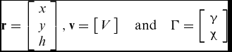
In order to simplify the derivation of the mathematical model for the flight path angle correction, the following matrix notation will be used in the paper:
 $$\begin{equation}
\boldsymbol{r} = \left[ {\begin{array}{*{20}{c}} x\\
\begin{array}{l} y\\ h \end{array} \end{array}} \right],\boldsymbol{v} = \left[ {\begin{array}{*{20}{c}} V \end{array}} \right]\quad{\rm{and}}\quad{\Gamma } = \left[ {\begin{array}{*{20}{c}} {\begin{array}{*{20}{c}} \gamma \\ \chi \end{array}} \end{array}} \right]
\end{equation}$$
In arbitrary time instance t = ti, the position of the rocket is defined by the point Mi (Fig. 1). The ballistic flight of the rockets from the point Mi to the target is defined by the velocity Vi and the flight path angles γi and χi. This ballistic flight provides rocket impact points at the position of the target. The equality of the rocket and target position at the impact point can be written in the vector form
 $$\begin{equation}
{\boldsymbol{r}_T} - {\boldsymbol{r}_F}\left( {{\boldsymbol{r}_i},\,{\boldsymbol{v}_i},\,\,{{\Gamma }_i},{t_i}} \right) = 0,
\end{equation}$$
where ti is the initial time for the ballistic flight from the arbitrary point; Mi,  ${\boldsymbol{r}_T} = {[ {\begin{array}{*{20}{c}} {{x_T}}&{{y_T}} \end{array}} ]^T}$ is the target position (for the surface target hT = 0),
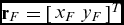 ${\boldsymbol{r}_F} = {[ {\begin{array}{*{20}{c}} {{x_F}}&{{y_F}} \end{array}} ]^T}$ is the impact point of the rocket at the end of the flight, t = tf,
 ${\boldsymbol{r}_i} = {[ {\begin{array}{*{20}{c}} {{x_i}}&{{y_i}}&{{h_i}} \end{array}} ]^T}$ is the rocket position on the nominal trajectory in the time instance t = ti, and
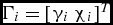 ${{\Gamma }_i} = {[ {\begin{array}{*{20}{c}} {{\gamma _i}}&{{\chi _i}} \end{array}} ]^T}$ is the flight path angles in the vertical and horizontal plane at the time instance t = ti.
If the flight path angles at the initial instance of the ballistic flight are equal to the required (correlated) ones, then the rocket position at the end of the flight (t = tf) will be equal to the target position.
 $$\begin{equation}
{\gamma _i} = {\gamma _c}, {\chi _i} = {\chi _c}
\end{equation}$$
 $$\begin{equation}
{\boldsymbol{r}_T} - \boldsymbol{r}\left( {{\boldsymbol{r}_i},\,{\boldsymbol{v}_i},\,\,{{\Gamma }_i},{t_f}} \right) = 0
\end{equation}$$
In the case of disturbances, the rocket will not be at the point Mi on the nominal trajectory but at some point M'i away from the nominal trajectory. The point Mi on the nominal trajectory corresponds to the time instance ti. Since there are some errors in the measurement of the current time, the measured time t'i corresponds to the point M'i. The values of the flight path angles, at the time instance t = t'i, can be determined from the condition that the ballistic flight of the rocket from this time instance can hit the target.
 $$\begin{equation}
{\gamma '_i} = {\gamma _c},\quad {\chi '_i} = {\chi _c}
\end{equation}$$
The correlated flight path angles at the point Mi can be defined in the matrix form 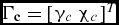 ${{\Gamma }_\boldsymbol{c}} = {[ {\begin{array}{*{20}{c}} {{\gamma _c}}&{{\chi _c}} \end{array}} ]^T}$. The general condition that a rocket with the ballistic flight from the point M'i hits the target is defined by the equation
 $$\begin{equation}
{\boldsymbol{r}_T} - {\boldsymbol{r}_F}\left( {{\boldsymbol{r}_i^\prime},{\boldsymbol{v}_i^\prime},\,{{\Gamma }_c}\,,\,{{t}_i^\prime}} \right) = 0
\end{equation}$$
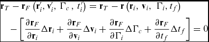
The second term in Equation (6) can be developed in the Taylor's series relative to the point Mi on the nominal trajectory.
 $$\begin{equation}
\begin{array}{l} {\boldsymbol{r}_T} - {\boldsymbol{r}_F}\left( {{\boldsymbol{r}_i'},{\boldsymbol{v}_i'},\,{{\Gamma }_c}\,,\,{{t}_i'}} \right) = {\boldsymbol{r}_T} - \boldsymbol{r}\left( {{\boldsymbol{r}_i},\,{\boldsymbol{v}_i},\,\,{{\Gamma }_i},{t_f}} \right) \\
\quad- \left[ {\displaystyle\frac{{\partial {\boldsymbol{r}_F}}}{{\partial {\boldsymbol{r}_i}}}\Delta {\boldsymbol{r}_i} + \displaystyle\frac{{\partial {\boldsymbol{r}_F}}}{{\partial {\boldsymbol{v}_i}}}\Delta {\boldsymbol{v}_i} + \displaystyle\frac{{\partial {\boldsymbol{r}_F}}}{{\partial {{\Gamma }_i}}}\Delta {{\Gamma }_c} + \displaystyle\frac{{\partial {\boldsymbol{r}_F}}}{{\partial {t_f}}}\Delta {t_f}} \right] = 0 \end{array}
\end{equation}$$
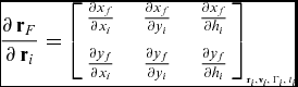
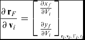
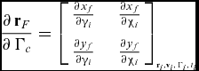
The partial derivatives are given for the nominal trajectory parameters r(ri, vi, Γi, ti).
 $$\begin{equation}
\frac{{\partial \,{\boldsymbol{r}_F}}}{{\partial \,{{\boldsymbol{r}}_i}}} = {\left[ {\begin{array}{*{20}{c}} {\frac{{\partial {x_f}}}{{\partial {x_i}}}}&\quad {\frac{{\partial {x_f}}}{{\partial {y_i}}}}&\quad {\frac{{\partial {x_f}}}{{\partial {h_i}}}}\\
{\frac{{\partial {y_f}}}{{\partial {x_i}}}}&\quad {\frac{{\partial {y_f}}}{{\partial {y_i}}}}&\quad {\frac{{\partial {y_f}}}{{\partial {h_i}}}} \end{array}} \right]_{_{{\boldsymbol{r}_i},{\boldsymbol{v}_i},\,{{\Gamma }_i},\,{t_i}}}}
\end{equation}$$
 $$\begin{equation}
\frac{{\partial \,{\boldsymbol{r}_F}}}{{\partial \,{\boldsymbol{v}_i}}} = {\left[ {\begin{array}{*{20}{c}} {\frac{{\partial {x_f}}}{{\partial {V_i}}}}\\
{\frac{{\partial {y_f}}}{{\partial {V_i}}}} \end{array}} \right]_{_{{\boldsymbol{r}_i},{\boldsymbol{v}_i},\,{{\Gamma }_i},\,{t_i}}}}
\end{equation}$$
 $$\begin{equation}
\frac{{\partial \,{\boldsymbol{r}_F}}}{{\partial \,{{\Gamma }_c}}} = {\left[ {\begin{array}{*{20}{c}} {\frac{{\partial {x_f}}}{{\partial {\gamma _i}}}}&\quad {\frac{{\partial {x_f}}}{{\partial {\chi _i}}}}\\
{\frac{{\partial {y_f}}}{{\partial {\gamma _i}}}}&\quad {\frac{{\partial {y_f}}}{{\partial {\chi _i}}}} \end{array}} \right]_{_{{\boldsymbol{r}_i},{\boldsymbol{v}_i},\,{{\Gamma }_i},\,{t_{i}}}}}
\end{equation}$$
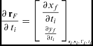 $$\begin{equation}
\frac{{\partial \,{\boldsymbol{r}_F}}}{{\partial \,{t_i}}} = {\left[ {\begin{array}{*{20}{c}} {\displaystyle\frac{{\partial {x_f}}}{{\partial {t_i}}}}\\
{\frac{{\partial {y_f}}}{{\partial {t_i}}}} \end{array}} \right]_{_{{\boldsymbol{r}_i},{\boldsymbol{v}_i},\,{{\Gamma }_i},\,{t_i}}}}
\end{equation}$$
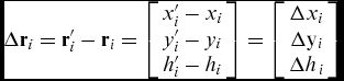 $$\begin{equation}
{\rm{\Delta }}{\boldsymbol{r}_i} = {\boldsymbol{r}_i'} - {\boldsymbol{r}_i} = \left[ {\begin{array}{*{20}{c}} {{{x}_i'} - {x_i}}\\
{{{y}_i'} - {y_i}}\\
{{{h}_i'} - {h_{i}}} \end{array}} \right] = \left[ {\begin{array}{*{20}{c}} {{\rm{\Delta }}{x_i}}\\
{{\rm{\Delta }}{{\rm{y}}_i}}\\
{{\rm{\Delta }}{h_{\,i}}} \end{array}} \right]
\end{equation}$$
 $$\begin{equation}
{\rm{\Delta }}{{\Gamma }_i} = {{\Gamma}_i'} - {{\Gamma }_i} = \left[ {\begin{array}{*{20}{c}} {{{\gamma}_i'} - {\gamma _i}}\\
{{{\chi}_i'} - {\chi _i}} \end{array}} \right] = \left[ {\begin{array}{*{20}{c}} {{\rm{\Delta }}{\gamma _i}}\\
{{\rm{\Delta }}{\chi _i}} \end{array}} \right]
\end{equation}$$
 $$\begin{equation}
{\rm{\Delta }}{\boldsymbol{v}_i} = {\boldsymbol{v'}_i} - {\boldsymbol{v}_i} = \left[ {\begin{array}{*{20}{c}} {{{V'}_i} - {V_i}} \end{array}} \right] = \left[ {\begin{array}{*{20}{c}} {\Delta {V_i}} \end{array}} \right]
\end{equation}$$
 $$\begin{equation}
{\boldsymbol{r}_T} - {\boldsymbol{r}_F}\left( {{\boldsymbol{r}_i},\,{\boldsymbol{v}_i},\,\,{{\Gamma }_i},{t_i}} \right) = 0
\end{equation}$$
Partial derivatives can be determined by the method of differential corrections. This method is related to the numerical determination of the first derivative of the trajectory coordinates relative to the parameters that define ballistic flight trajectory from the point Mi to the target.
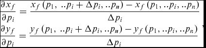 $$\begin{equation}
\begin{array}{l} \displaystyle\frac{{\partial {x_f}}}{{\partial {p_i}}} = \displaystyle\frac{{{x_f}\left( {{p_{1}},\,..{p_i} + \Delta {p_i},..{p_{n}}} \right) - {x_f}\left( {{p_{1}},..{p_{i}},..{p_{n}}} \right)}}{{\Delta {p_i}}}\\
\displaystyle\frac{{\partial {y_f}}}{{\partial {p_i}}} = \displaystyle\frac{{{y_f}\left( {{p_{1}},\,..{p_i} + \Delta {p_i},..{p_{n}}} \right) - {y_f}\left( {{p_{1}},..p{_i},..{p_{n}}} \right)}}{{\Delta {p_i}}} \end{array},
\end{equation}$$
wherep 1 = x, p 2 = y, p 3 = h, p 4 = V, p 5 = γ, p 6 = χ and p 7 = t.
The increment of the flight path angles due to disturbances can be determined from Equation (7) since the first two terms, rT and rF(ri, vi, Γi, t 0) , are equal.
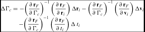 $$\begin{equation}
\begin{array}{l} \Delta {{\Gamma }_c} = - {\left( {\displaystyle\frac{{\partial \,{\boldsymbol{r}_F}}}{{\partial \,{{\Gamma }_c}}}} \right)^{ - 1}}\left( {\displaystyle\frac{{\partial \,{\boldsymbol{r}_F}}}{{\partial \,{\boldsymbol{r}_i}}}} \right)\Delta {\boldsymbol{r}_i} - {\left( {\displaystyle\frac{{\partial \,{\boldsymbol{r}_F}}}{{\partial \,{{\Gamma }_c}}}} \right)^{ - 1}}\left( {\displaystyle\frac{{\partial \,{\boldsymbol{r}_F}}}{{\partial \,{\boldsymbol{v}_i}}}} \right)\Delta {\boldsymbol{v}_i} \\
\quad \qquad - {\left( {\displaystyle\frac{{\partial \,{\boldsymbol{r}_F}}}{{\partial \,{{\Gamma }_c}}}} \right)^{ - 1}}\left( {\displaystyle\frac{{\partial \,{\boldsymbol{r}_F}}}{{\partial \,{t_i}}}} \right)\Delta \,{t_i} \end{array}
\end{equation}$$
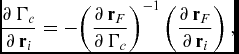
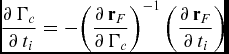
Equation (17) can be simplified by using a new notation of the matrix:
 $$\begin{equation}
\frac{{\partial \,{{\Gamma }_c}}}{{\partial \,{\boldsymbol{r}_i}}} = - {\left( {\frac{{\partial \,{\boldsymbol{r}_F}}}{{\partial \,{{\Gamma }_c}}}} \right)^{ - 1}}\left( {\frac{{\partial \,{\boldsymbol{r}_F}}}{{\partial \,{\boldsymbol{r}_i}}}} \right),
\end{equation}$$
 $$\begin{equation}
\frac{{\partial \,{{\Gamma }_c}}}{{\partial \,{\boldsymbol{v}_i}}} = - {\left( {\frac{{\partial \,{\boldsymbol{r}_F}}}{{\partial \,{{\Gamma }_c}}}} \right)^{ - 1}}\left( {\frac{{\partial \,{\boldsymbol{r}_F}}}{{\partial \,{\boldsymbol{v}_i}}}} \right)\,{\rm{and}}
\end{equation}$$
 $$\begin{equation}
\frac{{\partial \,{{\Gamma }_c}}}{{\,\partial \,{t_i}}} = - {\left( {\frac{{\partial \,{\boldsymbol{r}_F}}}{{\partial \,{{\Gamma }_c}}}} \right)^{ - 1}}\left( {\frac{{\partial \,{\boldsymbol{r}_F}}}{{\partial \,{t_i}}}} \right)
\end{equation}$$
Substituting Equations (18), (19) and (20) into Equation (17) the relation between the flight path angles increment ΔΓc and disturbances Δri, Δvi, Δti can be written in a simplified form:
 $$\begin{equation}
\Delta {{\Gamma }_c} = - \left( {\frac{{\partial \,{{\Gamma }_c}}}{{\partial \,{\boldsymbol{r}_i}\,}}} \right)\Delta {\boldsymbol{r}_i} - \left( {\frac{{\partial \,{{\Gamma }_c}}}{{\partial \,{\boldsymbol{v}_i}\,}}} \right)\Delta {\boldsymbol{v}_i} - \left( {\frac{{\partial \,{{\Gamma }_c}}}{{\,\partial \,{t_i}}}} \right)\Delta \,{t_i},
\end{equation}$$
where  $\Delta {{\Gamma }_c} = {[ {\begin{array}{*{20}{c}} {\Delta {\gamma _c}}&\quad {\Delta {\chi _c}} \end{array}} ]^T}$.
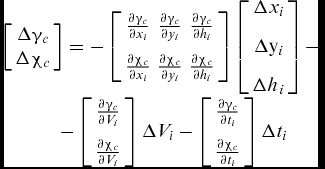
In general, there are coupling effects between the disturbances in the vertical and horizontal plane and the flight path correction in these two planes. In order to analyse these cross-influences, the matrix Equation (21) can be written in a developed form:
 $$\begin{equation}
\begin{array}{l} \left[ {\begin{array}{*{20}{c}} {\Delta {\gamma _c}}\\
{\Delta {\chi _c}} \end{array}} \right] = - \left[ {\begin{array}{*{20}{c}} {\frac{{\partial {\gamma _c}}}{{\partial {x_i}}}}&{\frac{{\partial {\gamma _c}}}{{\partial {y_i}}}}&{\frac{{\partial {\gamma _c}}}{{\partial {h_{i}}}}}\\
{\frac{{\partial {\chi _c}}}{{\partial {x_i}}}}&{\frac{{\partial {\chi _c}}}{{\partial {y_i}}}}&{\frac{{\partial {\chi _c}}}{{\partial {h_{i}}}}} \end{array}} \right]\left[ {\begin{array}{*{20}{c}} {{\rm{\Delta }}{x_i}}\\
{{\rm{\Delta }}{{\rm{y}}_i}}\\
{{\rm{\Delta }}{h_{\,i}}} \end{array}} \right] - \\
\quad \quad \quad - \left[ {\begin{array}{*{20}{c}} {\frac{{\partial {\gamma _c}}}{{\partial {V_i}}}}\\
{\frac{{\partial {\chi _c}}}{{\partial {V_i}}}} \end{array}} \right]\Delta {V_i} - \left[ {\begin{array}{*{20}{c}} {\frac{{\partial {\gamma _c}}}{{\partial {t_i}}}}\\
{\frac{{\partial {\chi _c}}}{{\partial {t_i}}}} \end{array}} \right]\Delta {t_i} \end{array}
\end{equation}$$
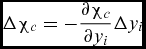
Based on the analysis of the rocket's ballistic flight, the variation of the flight path angle in the vertical plane (Δγi) creates only the variation of the range (Δxf); and, the variation of the flight path angle in the horizontal plane (Δχi) creates only the deviation of the rocket trajectory (Δyf).
Neglecting cross-coupling sensitive coefficients, Equation (23) can be written in the form of two separate equations. One equation gives the relation between the flight path angle increment in the vertical plane (Δγc) and disturbances Δxi, Δh i, ΔVi. The second equation (Equation (24)) gives the relation between the flight path angle variation in the horizontal plane (Δχc) and the displacement of the rocket relative to the nominal trajectory in the horizontal plane (Δyi).
 $$\begin{equation}
\Delta {\gamma _c} = - \frac{{\partial {\gamma _c}}}{{\partial {x_i}}}{\rm{\Delta }}{x_i} - \frac{{\partial {\gamma _c}}}{{\partial {h_{i}}}}{\rm{\Delta }}{h_{\,i}} - \frac{{\partial {\gamma _c}}}{{\partial {V_i}}}\Delta {V_i}
\end{equation}$$
 $$\begin{equation}
\Delta {\chi _c} = - \frac{{\partial {\chi _c}}}{{\partial {y_i}}}{\rm{\Delta }}{y_i}
\end{equation}$$
The total time of the rocket flight depends on the total impulse of the rocket engine. The corrective factor of the total impulse is a ratio between the actual total impulse and the nominal value of the total impulse (KItot = Itot/ItotN).
The diagrams of the velocities of the hypothetical rocket in function of time are given in Fig. 2 and the diagrams of the same velocities in function of the range are given in Fig. 3. There are three curves related to the three values of the corrective factors of the total impulse K Itot = 1.0, 0.96 and 1.04.
Rocket velocity in function of time.
Rocket velocity as a function of range.
The guidance method given in the paper requires two separate calculations:
2.1 Calculation before the missile flight
The nominal trajectory parameters (xi, yi, hi, Vi) and the sensitive coefficients (∂γc/∂xi, ∂γc/∂hi, ∂γc/∂Vi, ∂χc/∂yi) are calculated before launching the rocket using the following procedure:
• Calculation of the nominal trajectory (ballistic trajectory without external disturbances) by a 6DoF mathematical model of the missile in flight for a given target,
• Selection of the control points on the nominal trajectory from the condition that the linear interpolation of the trajectory parameters can be applied between two successive control points,
• Calculation of the corrective coefficients at the control points,
• Downloading of the nominal trajectory parameters and the corrective coefficients into the computer memory of rockets.
2.2 Calculation during the missile flight
• Selection of the control points based on the estimated parameters of the missile trajectory (SDINS – strap-down inertial navigation system),
• Calculation of the flight path angle correction based on the difference between the parameters of the estimated trajectory and the nominal one (23), (24),
• Calculation of the required (correlated) flight path angle by adding the flight path angle correction to the nominal value.
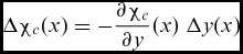
If the nominal trajectory parameters and the sensitive coefficients are a function of the range, then the flight path angle corrections (Δγc, Δχc) are also a function of the range. Consequently, the equation for the flight path correction can be written in a function of the range
 $$\begin{equation}
\Delta {\gamma _c}(x) = - \frac{{\partial {\gamma _c}}}{{\partial h}}{\rm{(}}x{\rm{)}}\;{\rm{\Delta }}h(x) - \frac{{\partial {\gamma _c}}}{{\partial V}}(x)\;\Delta V(x)
\end{equation}$$
 $$\begin{equation}
\Delta {\chi _c}(x) = - \frac{{\partial {\chi _c}}}{{\partial y}}{\rm{(}}x)\;{\rm{\Delta }}y(x)
\end{equation}$$
The correlated (desired) flight path angle in the vertical plane γc is obtained by adding the corrections Δγc to the nominal value of the flight path angle γn (Fig. 4). The nominal value of the flight path angle γn is obtained by linear interpolation between values of the flight path angle in two neighbouring control points i and i + 1.
 $$\begin{equation}
{\gamma _c}(x) = {\gamma _n}(x) + \Delta {\gamma _c}(x)
\end{equation}$$
Correlated flight path angle algorithm.
The flight path guidance loop (Fig. 5) is used to generate the demanded acceleration azd to eliminate the difference between the estimated ( $\tilde \gamma $) and desired (γc) values of the flight path angle(Reference Siouris8).
 $$\begin{equation}
{a_{zd}} = V\,{k_\gamma }\,\left[ {{\gamma _c} - (\tilde \gamma + {\tau _\gamma }\,\dot{\tilde\gamma} )} \right]
\end{equation}$$
Flight path angle guidance loop.
The lateral (normal) acceleration autopilot consists of a major accelerometer feedback loop to control the missile's lateral acceleration, and a minor rate feedback loop which provides the necessary damping of the missile pitch or yaw rates(Reference Siouris8,Reference Garnel11,Reference Blakelock12) . The design procedure for determination of the autopilot gains are based on classical and digital automatic control(Reference Garnel11-Reference Garnel14).
3.0 MATHEMATICAL MODEL OF SDINS NAVIGATION
SDINS navigation is widely used for estimation of the rocket position and velocity. Position and velocity estimation is based on the known initial position and initial velocity, and on measured specific forces and angular rates.
The differential equation of the rocket velocity in an arbitrary navigation axis system(Reference Rogers9) is
 $$\begin{equation}
{\dot{\boldsymbol{v}}}_e^n = {\boldsymbol{f}^n} - [ {2\boldsymbol{\omega }_{ie}^n + \boldsymbol{\omega }_{en}^n} ] \times \boldsymbol{v}_e^n + \boldsymbol{g}_l^n
\end{equation}$$
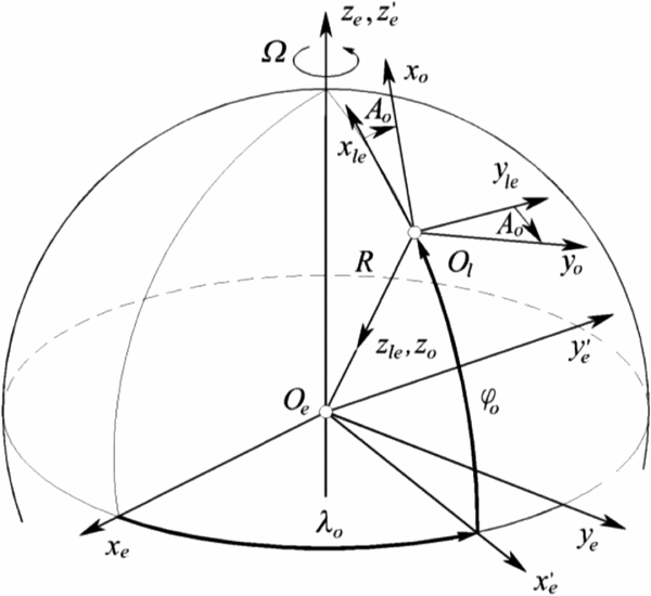
The position of the target relative to the launching position is defined by the basic axis system which is Earth's fixed axis system (F 0). The origin of the basic axis system coincides with the launch point. The Ox 0 axis is directed to the target. The plane Ox 0y 0 is tangent to the Earth's surface and the axis Oz 0 is directed vertically down (along the gravity vector). The position of F 0 is determined by the azimuth angle A 0 with respect to the local Earth-fixed reference frame Fle (Reference Titterton and Weston10) (Fig. 6).
Basic and local Earth-fixed and basic axis system.
Since guidance of the ground-to-ground rockets requires correction of the rocket position relative to the ballistic trajectory, the spherical axis system (FS) is used for the navigation system. Position of the spherical axis system relative to the basic axis system is defined by range angle σy and deviation angle σx (Fig. 7).
Spherical axis system.
The differential equation of the kinematic velocity in arbitrary navigation can be applied to the spherical axis system.
 $$\begin{equation}
{\dot{\boldsymbol{v}}}_e^s = {\boldsymbol{f}^s} - [ {2\boldsymbol{\omega }_{i\,e}^s + \boldsymbol{\omega }_{e\,s}^s} ] \times \boldsymbol{v}_e^s + \boldsymbol{g}_l^s,
\end{equation}$$
where vse is kinematic velocity of the rocket in spherical axis system
 $$\begin{equation}
\boldsymbol{v}_e^s = {\left[ {\begin{array}{*{20}{c}} {{v_{{x_s}}}}&{{v_{{y_{_s}}}}}&{{v_{{z_s}}}} \end{array}} \right]^T}
\end{equation}$$
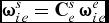
Angular rate of the Earth relative to the inertial axis system in spherical axis system ( $\boldsymbol{\omega }_{ie}^s$) can be obtained by multiplication of the angular rate of the Earth in Earth axis system
 $\boldsymbol{\omega }_{ie}^e = {[ {\begin{array}{*{20}{c}} 0&\quad 0&\quad\Omega \end{array}} ]^T}$ and transformation matrix from Earth axis system to spherical axis system.
 $$\begin{equation}
\boldsymbol{\omega }_{i\,e}^s = \boldsymbol{C}_e^s\,\boldsymbol{\omega }_{i\,e}^e
\end{equation}$$
Angular rate of the spherical axis system relative to the basic axis system is defined by two angular rates  ${\dot \sigma _x}$ and
 ${\dot \sigma _y}$. These two angular rates depend on rocket velocity relative to Earth in spherical axis system v xS, v yS and rocket altitude h.
 $$\begin{equation}
\boldsymbol{\omega }_{0s}^s = {\left[ {\begin{array}{*{20}{c}} 0&\quad {{{\dot \sigma }_y}}&\quad {{{\dot \sigma }_x}} \end{array}} \right]^T} = {\left[ {\begin{array}{*{20}{c}} 0&\quad {\displaystyle\frac{{{v_{{x_S}}}}}{{{R_0} + h}}}&\quad {\displaystyle\frac{{ - {v_{{y_S}}}}}{{{R_0} + h}}} \end{array}} \right]^T}
\end{equation}$$
Specific force in spherical axis system fs is determined by specific force in body axis system fb and transformation matrix from body to spherical axis system Csb(ψ, θ, ϕ).
 $$\begin{equation}
{\boldsymbol{f}^s} = \boldsymbol{C}_b^s\left( {\psi ,\theta ,\phi } \right)\,\,{\boldsymbol{f}^b}
\end{equation}$$
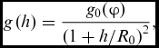
Gravity has only components in the zs direction of the spherical axis system
 $$\begin{equation}
{\boldsymbol{g}^s} = {\left[ {\begin{array}{*{20}{c}} 0&\quad 0&\quad {g\left( h \right)} \end{array}} \right]^T},
\end{equation}$$
where g(h) depends on rocket altitude (h) and the gravitational acceleration on the Earth's surface g 0(φ).
 $$\begin{equation}
g\left( h \right) = \frac{{{g_0}(\varphi )}}{{{{\left( {1 + h/{R_0}} \right)}^2}}},
\end{equation}$$
where φ is latitude.
The rate of change of direction cosine matrix  ${\dot{\boldsymbol{C}}}_b^s$ depends on angular rate of the body relative to spherical axis system in body axis system
 $\boldsymbol{\omega }_{s\,b}^b$.
 $$\begin{equation}
{\dot{\boldsymbol{C}}}_b^s = \boldsymbol{C}_b^s ({\boldsymbol{\omega }_{s\,b}^b \times }),\end{equation}$$
where  $( {\boldsymbol{\omega }_{s\,b}^b \times } )$ is skew-symmetric matrix of
 $\boldsymbol{\omega }_{s\,b}^b$ , which is a function of angular rate in body axis system
 $\boldsymbol{\omega }_{i\,b}^b$.
 $$\begin{equation}
\boldsymbol{\omega }_{s\,b}^b = \boldsymbol{\omega }_{i\,b}^b - \boldsymbol{C}_s^b\left[ {\boldsymbol{\omega }_{i\,e}^s + \boldsymbol{\omega }_{0s}^s} \right]
\end{equation}$$
Position of the rocket in basic axis system is defined by the kinematic velocity of the rocket in spherical axis system.
 $$\begin{equation}
{\left[ {\begin{array}{*{20}{c}} {\dot x}&\quad {\dot y}&\quad {\dot h} \end{array}} \right]^T} = {\left[\begin{array}{*{20}{c}} {\displaystyle\frac{{{v_{{x_S}}}}}{{1 + \displaystyle\frac{h}{{{R_0}}}}}}&\quad{\displaystyle\frac{{{v_{{y_S}}}}}{{1 + \displaystyle\frac{h}{{{R_0}}}}}}&\quad { - {v_{{z_S}}}} \end{array}\right]^T}
\end{equation}$$
4.0 RESULTS OF NUMERICAL SIMULATION
The basic dimensions of the artillery rocket analysed in the paper are given in Fig. 8. The total impulse of the thrust is Itot = 33400daNs. There are buster and sustainer phases of the solid rocket motors. The buster phase of the rocket motor lasts for 0.8s. The total burn out time is 4s. The total mass of the rocket is m 0 = 390kg.
Basic dimensions of the guided artillery rocket.
In order to verify the efficiency of the flight path guidance system, a computer program for rocket flight with a complete guidance and control system has been designed. The flight path guidance system has been included in the program together with synthetic pitch autopilots with accelerometers and rate gyros.
The flight path guidance system is used to generate the demanded acceleration azd to eliminate the difference between the estimated ( $\tilde \gamma $) and correlated (γc) values of the flight path angle. The synthesis of the guidance loop and the synthetic lateral autopilot is carried out by the classical theory of automatic control for a hypothetic missile with the maximum range of 50km(Reference Garnel11-Reference Ćuk, Ćurčin and Mandić14).
The efficiency of the proposed trajectory correction of artillery rockets is verified for the deviation of the total impulse. Since the total impulse is directly related to the thrust, the variation of the total impulse is obtained by multiplying the nominal values of the thrust with the corrective factors K Itot.
The ballistic trajectories for three values of the total impulse are given in Fig. 6. One trajectory is calculated for the nominal value of the total impulse. The other two trajectories are obtained for the thrust values 4% higher and 4% lower than the nominal ones. The corrective factors of the total impulse for these two cases are equal to K Itot = 1.04 and K Itot = 0.96. The miss distances at the impact point, due to 4% total impulse variations, are approximately 3km. On the basis of the achieved ranges of these three ballistic trajectories, it can be concluded that the total impulse deviation has a significant influence on the range variation.
The absolute values of the miss distance as a function of the percentage of the total impulse deviation for the ballistic flight of the rockets are given in Fig. 9. This diagram is obtained by the Monte Carlo simulation. One hundred runs have been performed with the standard deviation of the thrust of σF = 2.0%.
Miss distance due to total impulse deviation.
The trajectories of the rockets guided by the flight path steering guidance are given in Fig. 10. There are three trajectories (Fig. 10) related to the variation of the total impulse (K Itot = 1.0, 0.96 and 1.04). After the ballistic flight in the first phase, one second after the launch, the guidance with a trajectory correction starts. In all the analyses, the rocket is guided to the end of the flight (impact into a surface).
Influence of the total impulse variation on the guided rocket range.
When the total impulse is higher than the nominal total impulse, the flight path correction formula (Equation (26)) decreases the flight path angle relative to the nominal flight path angle and the trajectory is below the nominal trajectory. When the total impulse is lower than the nominal one, the required flight path angle is greater than the nominal one and the trajectory is above the nominal one.
The flight path angles, as a function of time, are given in Fig. 11 for three values of the total impulse corrective factors. The decrease of the flight path angles for the thrust greater than the nominal value is evident. For the thrust value lower than the nominal one, the increase of the flight path angles is required to hit the same target.
Flight path angle.
The diagrams of the control fin deflections in the pitch and yaw planes are given in Fig. 12. At the engine cut-off moment, the difference between the actual and nominal rocket velocity (Fig. 3) is evident. As a result, there is a sharp deflection of the fins in order to compensate for the differences between the actual and nominal velocity.
Fins deflection in the pitch.
The values of the angles-of-attack and the sideslip angles are related to the control fin deflection. This relation is determined by the aerodynamic configuration of the rocket. The diagrams of the angle-of-attack as a function of time are given in Fig. 13. The angle-of-attack is not greater than 5° in order to compensate for the maximum variation of the thrust (±4%).
Angles-of-attack.
The absolute values of the achieved range deviation as a function of the total impulse deviation for the guided artillery rocket are given in Fig. 14. It can be seen from the diagram that the maximum miss value is lower than 12m.
Absolute miss distance due to total impulse deviation.
5.0 MONTE CARLO ANALYSIS OF THE GUIDANCE SYSTEM ACCURACY
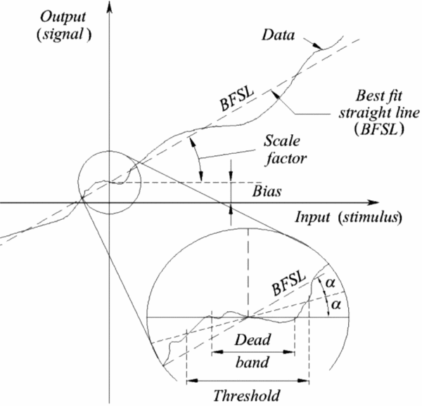
The specific forces fb and the angular rates  $\boldsymbol{\omega }_{i\,b}^b$ of the rockets are measured by accelerometers and rate gyros. The outputs of the accelerometers facc and the rate gyros
 ${\boldsymbol{\omega }_{{\rm{r}}{\rm{.g}}}}$ (Fig. 15) can be expressed mathematically in terms of the input values and the errors of measurements (Reference Rogers9,Reference Titterton and Weston10,15,16) .
Measurement model.
If the cross-coupling coefficients are neglected, a simplified mathematical model of measurements represents a function of the scale factor (S), the residual fixed bias (B), the random bias error (n) and the noise (w).
 $$\begin{equation}
{\boldsymbol{f}_{{\rm{acc}}}} = {\rm{(}}\boldsymbol{I} + {\boldsymbol{S}_{{\rm{acc}}}}{\rm{)}}\,\boldsymbol{f}_{}^b + {\boldsymbol{B}_{{\rm{acc}}}} + {\boldsymbol{n}_{{\rm{acc}}}} + {\boldsymbol{w}_{{\rm{acc}}}}
\end{equation}$$
 $$\begin{equation}
{\boldsymbol{f}_{{\rm{acc}}}} = {\boldsymbol{n}_{{\rm{acc}}}} + {\boldsymbol{w}_{{\rm{acc}}}}\,{\rm{for}}\;\left| {{\boldsymbol{f}_{{\rm{acc}}}}} \right| < \left| {{\boldsymbol{f}_{{\rm{d}}{\rm{.b}}}}} \right|
\end{equation}$$
 $$\begin{equation}
{\boldsymbol{\omega }_{{\rm{r}}{\rm{.g}}}} = {\rm{(}}\boldsymbol{I} + {\boldsymbol{S}_{{\rm{r}}{\rm{.g}}}}{\rm{)}}\boldsymbol{\omega }_{ib}^b + {\boldsymbol{B}_{{\rm{r}}{\rm{.g}}}} + {\boldsymbol{n}_{{\rm{r}}{\rm{.g}}}} + {\boldsymbol{w}_{{\rm{r}}{\rm{.g}}}}
\end{equation}$$
 $$\begin{equation}
{\boldsymbol{\omega }_{{\rm{r}}{\rm{.g}}}} = {\boldsymbol{n}_{{\rm{r}}{\rm{.g}}}} + {\boldsymbol{w}_{{\rm{r}}{\rm{.g}}}}\quad{\rm{for}}\quad\left| {{\boldsymbol{\omega }_{{\rm{r}}{\rm{.g}}}}} \right| < \left| {{\boldsymbol{w}_{{\rm{d}}{\rm{.b}}}}} \right|,
\end{equation}$$
The calculated values of the acceleration facc and the angular rates  ${\boldsymbol{\omega }_{{\rm{r}}{\rm{.g}}}}$ must be included in the navigation algorithm in order to analyse the influence of the IMU measurement errors on the trajectory parameters’ estimation. The specific force fb (Equation (34)) and the angular rate in the body axis system
 $\boldsymbol{\omega }_{i\,b}^b$ (Equation (38)) are replaced by facc and
 ${\boldsymbol{\omega }_{{\rm{r}}{\rm{.g}}}}$, respectively.
 $$\begin{equation}
{\boldsymbol{f}^s} = \boldsymbol{C}_b^s\left( {\psi ,\theta ,\phi } \right)\,\,{\boldsymbol{f}_{{\rm{acc}}}}
\end{equation}$$
 $$\begin{equation}
\boldsymbol{\omega }_{s\,b}^b = {\boldsymbol{\omega }_{{\rm{r}}{\rm{.g}}}} - \boldsymbol{C}_s^b\left[ {\boldsymbol{\omega }_{i\,e}^s + \boldsymbol{\omega }_{0s}^s} \right]
\end{equation}$$
In order to verify the influence of the IMU accelerometers and the rate gyros measurement errors on the accuracy of the artillery rocket guidance system, a complex software program for numerical simulation has been built. It is composed of a 6DoF mathematical model of the missile flight, the SDINS navigation algorithm, a mathematical model of IMU measurement errors, a guidance system with a lateral acceleration autopilot and a CEP calculation of impact point dispersion by the Monte Carlo simulation.
The most dominant external disturbances (thrust deviation, thrust eccentricity and wind) are considered for the analysis of the guidance system accuracy:
• Variation of the thrust follows the normal Gaussian distribution law: N(FN, σ(F)) , where σ (F)/FN = 0.5%,
• Variation of the thrust eccentricity magnitude (εF) follows the normal Gaussian distribution law N(0, σ(εF)). A usual value of σ(εF) = 1.0mrad. The angular position of the lateral thrust has the uniform distribution from 0 to 2π in the plane normal to the longitudinal axis φεF = U(0, 2π),
• Axial and lateral winds have the normal distribution N(0, σw) with zero mean values and the standard dispersion σwx = σwy = 1.0m/s.
Without a loss of generality, the parameters of the accelerometers and rate gyros measurements(17) are the same for all three axes (Table 1).
Parameters of the accelerometers and rate gyros measurements

It is shown that the flight path steering guidance system can compensate for all external disturbances without a miss at the target. In order to verify the influence of IMU measurement errors on the missile trajectory parameter estimation as well as on the guidance system accuracy, the numerical simulation of the guided ground-to-ground missile has been done with the IMU measurement error parameters, given in Table 1, without external disturbances. The impact point dispersion of the guided ground-to-ground missile at the range of 40.0km with only the IMU measurement errors (Fig. 16) has been obtained by the Monte Carlo simulation of 100 trajectories.
Impact point dispersion due to IMU measurement errors.
When the external disturbances are included in the numerical simulation, the impact point dispersion is equal to the impact point dispersion due to the IMU measurement errors (Fig. 17).
Impact point dispersion due to IMU measurement errors and external disturbances.
The efficiency of the ground-to-ground missile guidance system with a typical commercial low-cost IMU is obtained by comparing the impact point dispersion of guided artillery rockets to the impact point dispersion of unguided rockets (Fig. 18). The external disturbances are the same in both cases. It is evident that guidance guided artillery rockets with commercial low-cost IMUs can decrease impact point dispersion by a factor of five compared to the dispersion of unguided artillery rockets.
Impact point dispersion due to external disturbances.
6.0 CONCLUSION
The basic requirements for ground-to-ground rockets are increased range and accuracy. Both of these contradictory requirements can be met to some extent by using appropriate guidance and control systems. The guidance system based on the flight path steering method is used for trajectory correction. The flight path angle steering guidance algorithm requires the calculation of the nominal trajectory and the sensitivity coefficients at control points. The nominal trajectory is obtained by the numerical calculation of the ballistic flight of unguided rockets without disturbances. This trajectory and weighting factors at control points are calculated before the missile launch. The sampling interval of the control points has been chosen to fulfill the requirements that the position, velocity and sensitive coefficients between the control points can be obtained by linear interpolation.
The required (correlated) flight path angle is calculated by adding the correction to the nominal value of the flight path angle. To avoid normalisation of the time of flight to the values, the flight path angle is calculated as a function of the axial coordinate of the missile position. The correction of the flight path angle is a function of the difference between the actual trajectory and the nominal one in altitude, and the difference between the actual and nominal velocity. The flight path guidance system is realised with a synthetic pitch autopilot composed of an accelerometer and a rate gyro.
The efficiency of the flight path steering method developed in the paper has been verified for the artillery rocket with a maximum range of 50km. The influence of the total impulse variation is verified by a numerical simulation for the achieved range of 40km. The miss distance due to the 4% variation of the total impulse compared to the nominal value is 3km. The guidance system added to the considered rockets and disturbances decreases the miss distance to 12m. This relatively small miss distance is a result of the pitch rate in the feedback of the autopilot due to the influence of the gravity. The deflections of control fins are not equal to zero even for zero-demanded accelerations.
The strap-down navigation algorithm of the missile motion in the spherical axis system is used for trajectory estimation. The equation of missile motion in this axis system enables the determination of the trajectory parameters which can be used directly for the realisation of the flight path steering guidance system. Since the specific forces are measured by accelerometers and angular rates by rate gyros, the measurement errors are modelled as a function of the scale factor, bias instability, dead band and noise.
The efficiency of the artillery rockets with the flight path steering system has been analysed by a numerical simulation. There is no practical influence of external disturbances on the impact point dispersion. It is shown that IMU measurement errors are the dominant factor causing the impact point dispersion in guided artillery rockets. The influence of a typical commercial low-cost IMU has been analysed by the comparison of the impact point dispersion of unguided ballistic and guided artillery rockets. The required range and the external disturbances used for the numerical simulation are the same for both types of artillery rockets. It is shown that the impact point dispersion of guided artillery rockets with commercial low-cost IMUs decreased by a factor of five compared to the impact point dispersion of ballistic rockets.