Introduction
Recently, supercapacitors or electrochemical capacitors are regarded as potential alternative candidates for energy storage devices, including mobile phones, hybrid electric vehicles, and computer, owing to their higher power output, faster charge–discharge characteristics, longer lifespan, and safer operation [Reference Gao, Xuan, Xu, Liang, Han, Yang, Han, Wang and Du1, Reference Yi, Wu, Xie and Luo2]. During the past few decades, two kinds of supercapacitors—electrical double-layer capacitors (EDLCs) and pseudocapacitors—have been well developed based on an energy storage mechanism [Reference Li, Lei, Wang, Chen, Kang, Gu and Zhang3, Reference Chen, Yan, Luo, Gao, Huang, Han, Zeng and Zhu4, Reference Beka, Xia and Liu5]. Pseudocapacitors, which store electrical energy faradaically by electron charge transfer between electrolyte and electrode, such as metal oxides [Reference Chai, Wang, Wang, Li and Guo6, Reference Yumak, Bragg and Sabolsky7], hydroxides [Reference Yang and Li8, Reference Jiang, Cheng, Hu, Hu, Cao, Yan, Di, Wang and Hou9], sulfides [Reference Li, Wang, Xiao, Ouyang, Li and Liu10, Reference Cheng, Zhang, Wei, Liu, Cui, Zhang and Zhang11], and conductive polymers [Reference Smirnov, Tarasova, Vorobiov, Kasatkin, Mikli, Sokolova, Bobrova, Vassiljeva, Krumme and Yakimanskiy12, Reference Wu, Meng, Wang, Zhang and Wang13], offer much higher specific capacitance and energy density than EDLCs (carbonaceous materials), which store charges electrostatically and offer a high power density but relatively low energy density [Reference Heydari, Moosavifard, Shahraki and Elyasi14, Reference Yuan, Tang, Sui, Huang, Qi, Pu, Wei, He, Meng and Cao15, Reference Yang, Han, Sun, Yang, Hu, Li and Cao16]. The combination of these two energy storage mechanisms within hybrid materials has been under in-depth investigation to fulfill the requirements posed by various applications [Reference Sanchez, Pendashteh, Palma, Anderson and Marcilla17, Reference Yuksel, Kaplan, Bicer, Yurum, Gursel and Unalan18].
For the pseudocapacitive materials, the transition metal oxides and transition metal sulfides (TMSs) are highly applicable as electrode materials for supercapacitors owing to their superior electrochemical and electrocatalytic properties [Reference Xu, Lu, Huo, Li, Wang, Zhang, Gu and Hu19, Reference Meng, Sun, He, Teng and Xu20]. The TMS have attracted significant research interest for their high specific capacitance, environmental friendliness, chemical and thermal stability, and much higher electrical conductivity than their metal oxide counterparts [Reference Wang, Zhang, Guan, Fan, Zhang and Sun21, Reference Jin, Cui, Gao, Zhang, Yang and Li22, Reference Zhao, Huang, Zhang and Zhou23]. The metal sulfides composed of multiple transition metals, such as MCo2S4 (M = Ni, Zn, Fe, Mn, Cu, etc.), have explicitly interested owing to their higher electrical conductivity, richer redox reactions, and better electrochemical activity than single-component metal sulfides [Reference Huang, Quan, Liu, Chen, Cai and Zhan24, Reference Liu, Jiang, Sun, Xu, Zhou, Zhang and Yao25]. For example, Shen et al. [Reference Shen, Yu, Wu, Yu, Zhang and Lou26] reported a novel ball-in-ball hollow structure of ternary nickel cobalt sulfide (NiCo2S4), and it showed a high specific capacitance of 1036 F/g at a current density of 1.0 A/g. NiCo2S4/NiS hollow nanospheres showed the outstanding electrochemical properties, and NiCo2S4/NiS//activated carbon (AC) asymmetric supercapacitor (ASC), which has a stable voltage window of 1.6 V, also achieved a high energy density of 43.7 W h/kg [Reference Xu, Lin, Wu, Huang, Fan, He, Wang and Xu27]. Chen et al. [Reference Chen, Zuo, Zhang and Gao28] synthesized ultrathin CuCo2S4 nanosheets, which exhibited a better specific capacitance of 1742 F/g at a current density of 10 A/g.
As one of the most promising ternary metal sulfides, nickel cobalt sulfides (Ni–Co–S) demonstrate an excellent electronic conductivity, which is approximately twice that of the nickel–cobalt oxides and much superior to that of the binary metal sulfides [Reference Liu, Lu, Huang, Sun, Yu, Evariste, Jiang and Yao29]. For example, nickel cobalt sulfide ultrathin nanosheets have been grown directly on nickel foam substrate and have an ultrahigh specific capacitance of 1712 F/g at a current density of 1 A/g with excellent cyclic stability [Reference Sahoo, Naik, Late and Rout30].
Recently, many types of ternary metal sulfides with different transition metals have also been synthesized and showed better performance for supercapacitors. For example, a zinc cobalt sulfide nanosheet array derived from a 2D bimetallic metal–organic frameworks for high-performance supercapacitors has been prepared, and it showed excellent electrochemical performance (2354.3 F/g and 88.6% retention over 1000 cycles), and an ASC device assembled from Zn–Co–S/NF and AC electrodes delivered the highest energy density of 31.9 W h/kg and a maximum power density of 8.5 kW/kg [Reference Tao, Han, Cheng, Yang, Yang, Ma and Han31]. Balamurugan et al. [Reference Balamurugan, Li, Peera, Kim and Lee32] have fabricated an ultrathin ternary metal sulfide nanosheet (Co–Mo–S NS) with hierarchical architecture, which exhibited an ultra-high specific capacitance of 2343 F/g at a current density of 1 mA/cm2 and exceptional cycling performance of 96.6% capacitance retention after 20,000 cycles.
Unfortunately, the development of ternary metal sulfide electrode materials is limited by the slow ion/electron transfer rate and volume instability during the redox reaction process [Reference Han, Xuan, Gao, Liang, Yang, Xu, Han and Du33, Reference Lin, Yan, Liu, Chang, Yao, Lin, Lu and Han34, Reference Shen, Xu, Dong, Zhang, Baines, Ji, Pei and Ye35]. To overcome this problem, reduced graphene oxide (rGO) has been introduced to decorate nanostructured pseudocapacitive ternary metal sulfides to buffer volume change and provide the large surface area for electron transport, improving their cycle stability based on its superior electrical conductivity, a high theoretical surface area of 2630 m2/g and chemical stability [Reference Fulari, Reddy, Jadhav, Ghodake, Kim and Lohar36, Reference Huang, Zhang, Liu and Liu37, Reference Wan, Shen, Zhang and Li38, Reference Gong, Zhao, Wang and Xu39, Reference Zhang, Chen, Huang, Chen and Guo40].
Herein, hierarchical mesoporous Zn–Ni–Co–S microspheres grown on rGO/nickel foam (Zn–Ni–Co–S–rGO/NF) have been prepared by a two-step hydrothermal method. The effect of different sulfurization time on the morphology and capacity of composites was investigated. An ASC was further fabricated using Zn–Ni–Co–S–rGO/NF-3h composite and AC as the positive and the negative electrodes, respectively.
Results and discussion
Morphologies and structures of Zn–Ni–Co–S–rGO/NF microspheres composites
The hierarchical porous Zn–Ni–Co–S–rGO/NF microsphere composites were synthesized via a two-step hydrothermal method. In the first step, the GO on NF was transformed to rGO by reduction process, and Zn–Ni–Co precursors were grown by hydrothermally treating Zn2+, Ni2+, and Co2+ in the presence of urea to provide a large surface and homogeneous nucleation. NH4F was added to activate the substrate material for producing more active sites for nucleation, then the Zn–Ni–Co–rGO/NF was obtained. In the second step, Zn–Ni–Co–S–rGO/NF composites were synthesized by an ion exchange reaction using thioacetamide (TAA) as S2− source. A color change of the sample from pink to dark was observed after the reaction process, indicating the conversion of Zn–Ni–Co–rGO/NF into Zn–Ni–Co–S–rGO/NF. Finally, the samples were calcined at 350 °C for 2 h to obtain the hierarchical porous Zn–Ni–Co–S–rGO/NF mesosphere composites.
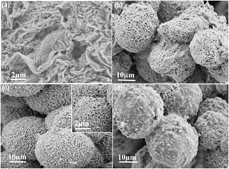
The morphologies of Zn–Ni–Co–S–rGO/NF composites at different sulfurization time are first characterized by scanning electron microscope (SEM), as shown in Fig. 1. First, the rGO is coated on NF for Zn–Ni–Co–S growth. The SEM image [Fig. 1(a)] clearly shows that rGO covered NF, which is beneficial for the growth of Zn–Ni–Co–S–rGO/NF microspheres because of its higher surface area, which improves the contact with the other components, its unique basal plane structure to load nanoparticles, and some oxygen-containing groups like hydroxyl, epoxide, and carboxyl act as nucleation centers for the growth of nanoparticles [Reference Alam, Sharma and Kumar41]. The sulfurization process is described as an ion exchange reaction, where the as-prepared Zn–Ni–Co–rGO/NF transferred into TAA (C2H5NS) solution, in which the surface oxygen atoms on Zn–Ni–Co precursor directly react with S2− ions through an anion exchange to form Zn–Ni–Co–S–rGO/NF composite. At the sulfurization time of 1 h [Fig. 1(b)], the surfaces of microspheres are a little rough and porous, suggesting that the sulfurization reaction is not complete [Reference Shen, Yu, Wu, Yu, Zhang and Lou26]. When the sulfurization reaction time reached 3 h [Figs. 1(c) and S1], the Zn–Ni–Co–S–rGO/NF microspheres show the structure with relatively more porosity [inset in Fig. 1(c)], which not only provides a larger surface for electron transportation and rapid redox reactions but also offers a shorter route for electrons/ions, which is beneficial for high electrochemical performance [Reference Li, Balamurugan, Kim and Lee42]. When the reaction time reached 5 h [Fig. 1(d)], the microspheres are much thick and dense which would be originated from excessive S2− anions released from TAA during the ion exchange reaction, and this could reduce the active sites, hindering the efficient utilization of composite to some degree.
SEM images of (a) rGO/NF and Zn–Ni–Co–S–rGO/NF microspheres derived at different sulfurization time: (b) Zn–Ni–Co–S–rGO/NF-1h, (c) Zn–Ni–Co–S–rGO/NF-3h, and (d) Zn–Ni–Co–S–rGO/NF-5h.

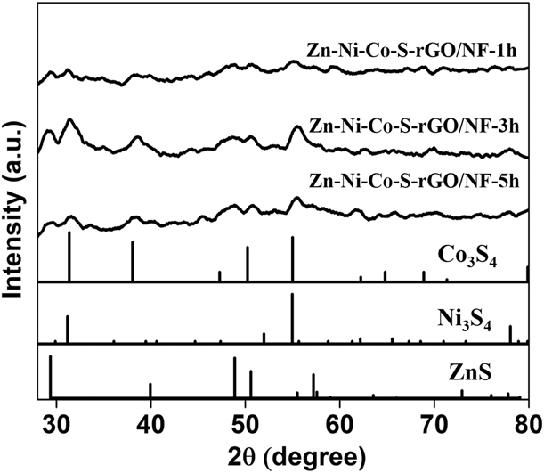
The crystal structure was analyzed by X-ray diffractometer (XRD) analysis. The XRD patterns of Zn–Ni–Co–S–rGO/NF samples at different sulfurization time of 1, 3, and 5 h are shown in Fig. 2. As shown in XRD patterns, all peaks are corresponding to the Co3S4 (ICDD no. 42-1448), Ni3S4 (ICDD no. 43-1469), and ZnS (ICDD no. 36-1450) phases. The high-intensity diffraction peaks at 29.2°, 50.5°, and 48.8° can be indexed to the (002), (110), and (103) of ZnS (ICDD no. 36-1450), respectively; 31.3°, 38.1°, and 61.8 indexed to the (311), (400), and (511) of Co3S4 (ICDD no. 42-1448), respectively; and 55.6° and 77.6° indexed to (311) and (331) of Ni3S4 (ICDD no. 43-1469), respectively. The slight mismatch in some diffraction peaks with pure phase peaks at high angle direction can be ascribed to the small crystallite sizes of samples due to the low crystallinity of rGO, leading to peaks broadening [Reference Vignesh and Navamathavan43].
XRD patterns of Zn–Ni–Co–S–rGO/NF composites at sulfurization time 1, 3, and 5 h.

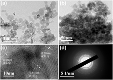
The transmission electron microscopy (TEM) test was performed to evaluate the internal nanostructure of the Zn–Ni–Co–S–rGO/NF-3h microspheres, as shown in Fig. 3. In Fig. 3(a), Zn–Ni–Co–S–rGO/NF-3h displays a nanosphere structure. The Zn–Ni–Co–S–rGO/NF-3h composite is constructed by multiple Zn–Ni–Co–S–rGO/NF-3h particles with some visible pores dispersed on the nanospheres, as clearly observed in Fig. 3(b). This porous structure is worth in increasing the number of active sites participating in electron transfer reaction by increasing the specific surface area of composite and helping the electrolyte ions to penetrate, showing the excellent performance of Zn–Ni–Co–S–rGO/NF-3h [Reference Wang, Zheng, Li, Ma, Yang and Wang44].
(a, b) TEM images of Ni–Co–S–rGO/NF-3h, (c) high-resolution TEM image of Ni–Co–S–rGO/NF-3h, and (d) the corresponding selected area electron diffraction pattern.

The high-resolution -TEM image of Zn–Ni–Co–S–rGO/NF-3h microspheres displays explicit lattice fringes with lattice distance of 0.55, 0.33, and 0.28 nm, indexed with the (111), (220), and (311) crystallographic plane of Co3S4 (ICDD no. 42-1448), as shown in Fig. 3(c). The selected area electron diffraction image shown in Fig. 3(d) shows well-defined diffraction rings, demonstrating the polycrystalline nature of Zn–Ni–Co–S–rGO/NF-3h composite. The TEM analysis indicates that Zn–Ni–Co–S–rGO/NF-3h electrode material has a porous structure, which is an essential factor for increasing the electrochemical performance.
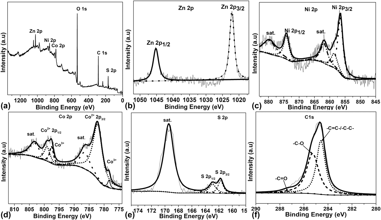
The elemental composition and valence states of Zn–Ni–Co–S–rGO/NF-3h composite were investigated via X-ray photoelectron spectroscopy (XPS) measurements. Figure 4(a) shows the survey spectrum, which confirms the presence of Zn, Ni, Co, S, O, and C elements in the product. The presence of Zn, Ni, Co, and S shows the successful growth of Zn–Ni–Co–S–rGO/NF surface. The elements C and O are mainly from graphene oxide exposed on the surface of NF and the air. The high-resolution Zn 2p spectrum [Fig. 4(b)] reveals two deconvoluted peaks at 1022.18 eV for Zn 2p 3/2 and 1045.28 eV for Zn 2p 1/2, suggesting the presence of Zn2+ ion in the Zn–Ni–Co–S–rGO/NF [Reference Lv, Liu, Shi, Che, Mu, Guo and Zhang45]. As shown in Fig. 4(c), the Ni 2p spectrum is well fitted with two spin–orbit doublets (Ni 2p 1/2, 874.18 eV) and (Ni 2p 3/2, 856.58 eV), which indicates the presence of Ni2+ and Ni3+ oxidation states, respectively, and each peak is followed by its shake-up satellite peak, denoted as “sat.” [Reference He, Liang, Ji, Sun, Zhai and Xu46]. The Co 2p spectrum also can be fitted with two shake-up satellites and two spin–orbit doublets (Co 2p 3/2: 778.38 eV and Co 2p 1/2: 799.18 eV) [Fig. 4(d)], which characterize the presence of Co2+ and Co3+ in the sample [Reference Lin, Li, Hussain, Zhao, Wu, Peng and Hu47]. The high-resolution S 2p spectrum [Fig. 4(e)] shows a shake-up satellite (sat.) at 169.48 eV and two peaks at 162.78 eV and 161.78 eV indexed as S 2p 1/2 and S 2p 3/2, respectively, confirming the presence of S2− [Reference Tong, Bai, Yue, Gao, Lu, Shen, Dong, Zhu, He and Zhang48] The C 1s spectrum [Fig. 4(f)] exhibits three distinct peaks at 284.58, 285.28, and 287.38 eV, corresponding to the oxygenated carbon species –C=C–/–C–C–, –C–O, and –C=O, respectively [Reference Liu, Niu, Yang, Cheng, Ye, Zhu, Wang, Cao and Yan49]. The XPS patterns analysis shows that sample is composed of Zn2+, Co2+, Co3+, Ni2+, Ni3+, S2−, and C, indicating the formation of Zn–Ni–Co–S–rGO/NF-3h composite.
(a) XPS survey spectrum of Zn–Ni–Co–S–rGO/NF-3h, XPS spectra of Zn–Ni–Co–S–rGO/NF-3h in the regions of (b) Zn 2p, (c) Co 2p, (d) Ni 2p, (e) S 2p, and (f) C 1s.

The surface area and the porous distributions of the Zn–Ni–Co–S–rGO/NF composites were measured by Brunauer-Emmett-Teller (BET) analysis, as shown in Fig. S2; the adsorption–desorption curve indicates that both of them have a type IV isotherm, suggesting the mesoporous nature of the materials. According to the calculation, the surface area of the samples Zn–Ni–Co–S–rGO/NF-1h, Zn–Ni–Co–S–rGO/NF-3h, and Zn–Ni–Co–S–rGO/NF-5h is estimated to be 43.27, 61.05, and 38.07 m2/g, and the average pore size is 4.34, 5.09, and 4.14 nm, respectively, indicating that the sample Zn–Ni–Co–S–rGO/NF-3h is mesoporous with a larger specific surface area.
Electrochemical characteristics of the Zn–Ni–Co–S–rGO/NF microsphere electrodes
The electrochemical performance of the prepared Zn–Ni–Co–S–rGO/NF composite was investigated to determine its utility as an electrode material for supercapacitors. The electrochemical performances of Zn–Ni–Co–S–rGO/NF electrodes were evaluated using a three-electrode cell configuration in 2 M KOH electrolyte. As shown in Fig. S3, the cyclic voltammetry (CV) curves of the three Zn–Ni–Co–S–rGO/NF electrodes at different sulfurization time at a scan rate of 2.5 mV/s within the potential window between 0 and 0.6 V were tested.
As shown in Fig. S3(A), there is a pair of redox peaks at low scan rates on Zn–Ni–Co–S–rGO/NF-3h electrode, indicating the better pseudocapacitive properties of Zn–Ni–Co–S–rGO/NF-3h electrode than the other electrodes. The large deviation from an ideal rectangular and weak redox peaks for all electrodes can be attributed to the dissolution of Zn species in the strong alkaline electrolyte and the irreversible phase transformations of Ni3S2 or Co9S8 to the Ni(OH)x or Co(OH)x during redox reactions [Reference Huang, Quan, Liu, Chen, Cai and Zhan24]. The Zn–Ni–Co–S–rGO/NF-3h electrode exhibits the maximum integral area of the CV curve, indicating the large specific capacitance behavior compared with the other electrodes (Zn–Ni–Co–S–rGO/NF-1h and Zn–Ni–Co–S–rGO/NF-5h).
During the electrochemical process, the faradaic redox reactions related to M–S/M–S–OH (M refers to Zn, Ni, and Co) occurred. The possible redox reactions of Zn–Ni–Co–S–rGO/NF electrodes can be determined by the following equations:
 $${\rm{N}}{{\rm{i}}_3}{{\rm{S}}_2} + 3{\rm{O}}{{\rm{H}}^ - } \leftrightarrow {\rm{N}}{{\rm{i}}_3}{{\rm{S}}_2}{\left( {{\rm{OH}}} \right)_3} + 3{{\rm{e}}^ - }\quad ,$$
 $${\rm{C}}{{\rm{o}}_9}{{\rm{S}}_8} + 9{\rm{O}}{{\rm{H}}^ - } \leftrightarrow {\rm{C}}{{\rm{o}}_9}{{\rm{S}}_8}{\left( {{\rm{OH}}} \right)_9} + 9{{\rm{e}}^ - }\quad ,$$
 $${\rm{C}}{{\rm{o}}_9}{{\rm{S}}_8}{\left( {{\rm{OH}}} \right)_9} + 9{\rm{O}}{{\rm{H}}^ - } \leftrightarrow {\rm{C}}{{\rm{o}}_9}{{\rm{S}}_8}{{\rm{O}}_9} + 9{{\rm{H}}_2}{\rm{O}} + 9{{\rm{e}}^ - }\quad ,$$
 $${\rm{ZnS}} + {\rm{O}}{{\rm{H}}^ - } \leftrightarrow {\rm{ZnSOH}} + {{\rm{e}}^ - }\quad ,$$
 $${\rm{CoS}} + {\rm{O}}{{\rm{H}}^ - } \leftrightarrow {\rm{ZnSOH}} + {{\rm{e}}^ - }\quad ,$$
 $${\rm{CoSOH}} + {\rm{O}}{{\rm{H}}^ - } \leftrightarrow {\rm{CoSO}} + {{\rm{H}}_2}{\rm{O}} + {{\rm{e}}^ - }\quad .$$
For evaluating the charge storage capacity, the electrochemical performances of the Zn–Ni–Co–S–rGO/NF-1h, Zn–Ni–Co–S–rGO/NF-3h, and Zn–Ni–Co–S–rGO/NF-5h composite electrodes were measured within a potential window range of 0–0.45 V based on galvanostatic charge–discharge (GCD) test. As shown in Fig. S3(B), by the CV results, the Zn–Ni–Co–S–rGO/NF-3h electrode exhibits a much longer discharge time than the other two electrodes under the same current density. The conductivities and electrochemical kinetic properties of Zn–Ni–Co–S–rGO/NF electrodes are studied by electrochemical impedance spectroscopy (EIS) measurements in the 0.01–100 kHz frequency range. All samples show the straight line at low frequency and small semicircle at high frequency, as shown in Figs. S3(C) and S3(D). Equivalent circuit model corresponding to EIS is shown in the inset in Fig. S3(D). In the equivalent circuit, R s represents the electrolyte resistance, the resistance of electrodes, and the contact resistance at the interface between electrode materials and current collector, while R ct and C dl stand for charge transfer resistance and double layer capacitor, respectively, and the Warburg behavior (W) rises from diffusion resistance of electrolyte ions [Reference Sahoo, Naik, Late and Rout30]. The faradaic charge transfer resistance value was calculated using the x-axis intercept at high frequency with the diameter of the semicircle. The Zn–Ni–Co–S–rGO/NF-3h electrode exhibits smaller R ct value of 0.60 Ω compared with 0.65 Ω and 0.82 Ω of Zn–Ni–Co–S–rGO/NF-1h and Zn–Ni–Co–S–rGO/NF-5h, respectively, as shown in Fig. S4(C); these results indicate that Zn–Ni–Co–S–rGO/NF-3h composite has excellent electrical conductivity and ion diffusion behavior, which can shorten the ion/charge transportation path.
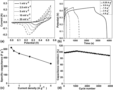
Further electrochemical behavior characterizations were performed on the Zn–Ni–Co–S–rGO/NF-3h electrode, as shown in Fig. 5. Figure 5(a) shows the CV curves of Zn–Ni–Co–S–rGO/NF-3h electrode at different scan rates from 1 to 20 mV/s. The ideal rectangular characteristic and redox peaks of CV curves can be found at low scan rates, which indicated an ideal capacitive behavior for Zn–Ni–Co–S–rGO/NF-3h electrode, and at high scan rates there is a slight deviation from ideal rectangular and the shift of oxidation peaks toward anodic direction and reduction peaks toward cathodic direction, which can be ascribed to the internal resistance of electrode and polarization phenomena involved in faster electron transfer process during high scan rates on the surface of electrode material [Reference Zhou, Yan, Yang, Lv, Kang and Liu50]. Figure 5(b) shows the GCD curves of Zn–Ni–Co–S–rGO/NF-3h electrode measured at current densities ranging from 0.25 to 4 A/g in a potential window of 0–0.45 V. The GCD curves exhibit almost symmetric shape with retention capacitance of 97.8% at current density of 2 A/g, which indicates a highly reversible electrochemical behavior. The calculated specific capacitances are 627.7, 569.1, 523.7, 469.7, and 346.6 F/g at 0.25, 0.5, 1, 2, and 4 A/g, respectively [Fig. 5(c)]. The Zn–Ni–Co–S–rGO/NF-3h composite displays the highest specific capacitance among all the samples, which can be attributed to the maximum of S2− released during ion exchange process and produce a porous structure that afforded more active sites. Also, the rate capability of Zn–Ni–Co–S–rGO/NF-3h composite can be increased by the fast diffusion of electrolytic ions at a high current density [Reference Zhang, Yin, Liu, Wang and Gu51]. Figure 5(d) shows the cycling stability of Zn–Ni–Co–S–rGO/NF-3h composite at a current density of 2 A/g through 4000 cycles. The cycling performance of Zn–Ni–Co–S–rGO/NF-3h is increasing at the initial stage, owing to the increased interface area within the electrode and electrolyte and the gradual activation of the composite [Reference Zhao, Li, Zhang, Zhang, Wang, Sun, Wang, Xie, Lu, Lu and Yao52]. The capacitance retention of Zn–Ni–Co–S–rGO/NF-3h composite was 97.8% after 4000 cycles; this can be attributed to the porous structure of Zn–Ni–Co–S–rGO/NF-3h, which can produce more electroactive sites and better conductivity for electrochemical reactions, leading to excellent cycling stability. The comparison between other ternary metal sulfide–based electrodes and our electrode is shown in Table SI.
(a) CV curves of Zn–Ni–Co–S–rGO/NF-3h at different scan rates, (b) GCD curves, and (c) calculated specific capacitance of Zn–Ni–Co–S–rGO/NF-3h at different current densities and (d) cycling performance of Zn–Ni–Co–S–rGO/NF-3h at 2 A/g.

Electrochemical properties of ASCs
To build a high–energy density ASC, AC was chosen as a negative electrode because of its high specific capacitance and good electrical conductivity compared with other carbon-based materials [Reference Sivakumar, Jana, Kota, Jung, Gedanken and Park53]. The AC electrode was prepared by mixing activated charcoal, carbon black, and polyvinylidene fluoride with a mass ratio of 80:10:10 in the solution of N-methylpyrrolidone (NMP) to make a slurry. Then, the slurry was pressed onto the Ni foam electrode and dried at 60 °C for 12 h. The AC electrode was also studied as a binder-free electrode for supercapacitors within the potential window of −1.0 to 0 V in the three-electrode working station as shown in Fig. S4.
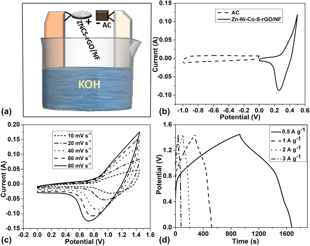
To evaluate the Zn–Ni–Co–S–rGO/NF-3h and AC electrodes for electrochemical energy storage applications, the flexible supercapacitors are assembled and the electrochemical properties are investigated by the two-electrode system with 2 M KOH as the electrolyte. Figure 6(a) shows a schematic diagram of ASCs composed of Zn–Ni–Co–S–rGO/NF-3h as a positive electrode and AC as a negative electrode in 2 M KOH electrolyte. Figure 6(b) shows the CV curves of Zn–Ni–Co–S–rGO/NF-3h and AC electrodes measured at a scan rate of 10 mV/s with a potential window of 0–0.45 V and −1 to 0 V, respectively. Therefore, if these two electrodes are assembled to make an ASC device, the operation potential of supercapacitors assembled can operate from 0 to 1.45 V.
(a) Schematic illustration of the Zn–Ni–Co–S–rGO/NF-3h//AC ASC device, (b) CV curves of Zn–Ni–Co–S–rGO/NF-3h and AC in the three-electrode system, (c) CV curves of the ASCs at different scan rates, and (d) GCD curves of ASCs at different current densities.
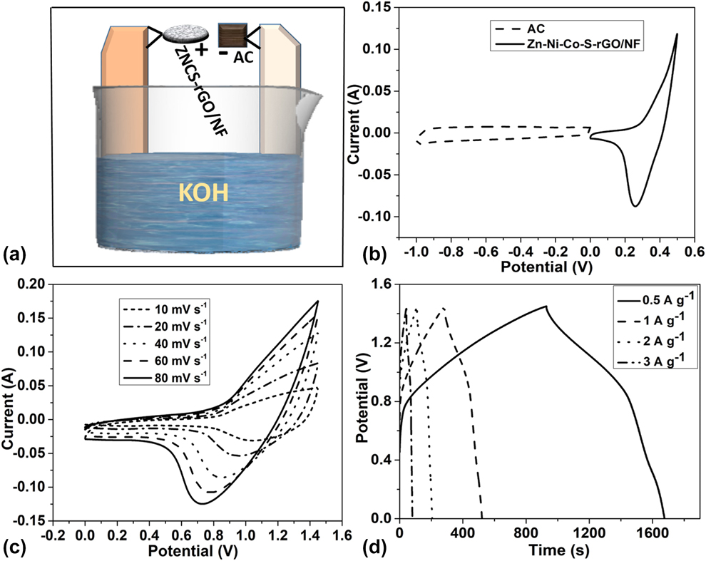
Figure 6(c) presents the CV curves of the ASCs with potential window from 0 to 1.45 V at different scan rates; it is seen there is no much deformation in the CV curves as the scan rate increased and a little shift of oxidation peak is observed, also redox peaks are still observable even at high current density of 80 mV/s, indicating the ASC device has a good capacitive behavior and a reasonable rate capability. Figure 6(d) displays the GCD curves of ASCs at different current densities ranging from 0.5 to 3 A/g. The specific capacitance of the Zn–Ni–Co–S–rGO/NF-3h//AC ASC device was calculated based on the total weight of electroactive materials of the two electrodes, and it exhibits the highest specific capacitance of 260.13 F/g at 0.5 A/g, leading to high energy density and power density of our device.
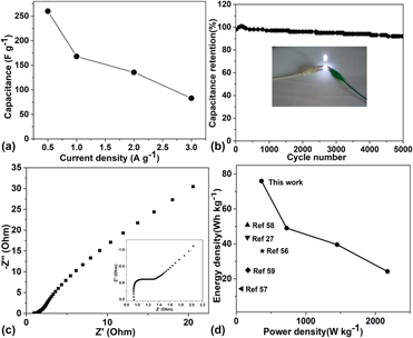
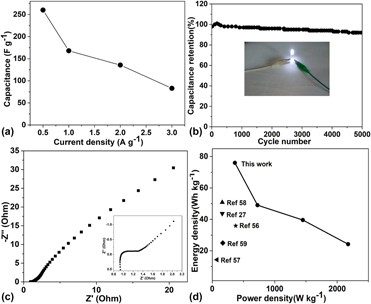
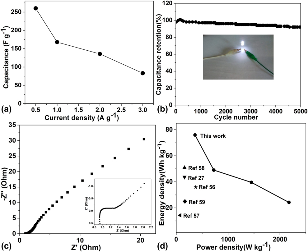
As shown in Fig. 7(a), the specific capacitance of ASC can reach a high value of 260.13 F/g at a current density of 0.5 A/g. The cycling stability is a crucial factor in determining the supercapacitors for practical applications. As shown in Fig. 7(b), the capacitance retention of ASC device is about 91.2% after 5000 cycles at a current density of 2.0 A/g, which exhibit the excellent stability of supercapacitor assembled. As shown in the inset in Fig. 7(b), the light-emitting diode (LED) can be illuminated by two ASC devices in series. Figure 7(c) shows open circuit Nyquist plot in the range of 0.01–100 kHz, presenting the electron conductivity of our ASC device. The Zn–Ni–Co–S–rGO/NF-3h//AC ASC device exhibited low faradaic charge transfer resistance (R ct) in the high-frequency range with a short semicircle. The low R ct indicates the large electroactive surface area, which can be attributed to the superior specific surface area and electrical conductivity of the Zn–Ni–Co–S–rGO/NF-3h electrode. Figure 7(d) shows the Ragone plot (energy density versus power density) of the ASC device. Using the following equations [Reference Feng, Liu, Sun, Zhu, Chen, Meng, Li, Yang, Zhang and Liu54, Reference Wang, Zhang, Li, Ma, Liu, Pan, Wang and Wang55]:
 $$E = {1 \over {7.2}}C{\left( {\Delta V} \right)^2}\quad ,$$
 $$P = 3600{E \over {\Delta t}}\quad ,$$
the specific capacitance (C), working potential windows (ΔV), and discharge time (Δt) of ASC and the energy density (E) and the power density (P) were calculated. The fabricated ASC device can exhibit a high energy density of 75.96 W h/kg at a power density of 362.49 W/kg and maintain the energy density of 24.22 W h/kg at a high power density of 2174.9 W/kg. The energy densities of our ASC device are considerably higher than those of other ASC devices, such as NiCo2S4/NiS//AC exhibited high energy density of 43.7 W h/kg at power density of 160 W/kg [Reference Xu, Lin, Wu, Huang, Fan, He, Wang and Xu27], Ni–Co–Fe–S@NCAs-NP//rGO-NF showed energy density of 35.9 W h/kg at power density of 375 W/kg [Reference Rahimia, Shahrokhian and Hosseini56], MCS/GNF//AC achieved energy density of 14.33 W h/kg at power density of 74.87 W/kg [Reference Yu, Li, Ma, Liu, Liu and Li57], Ppy@NiCo2S4//N–C exhibited the energy density of 50.82 W h/kg at power density of 160 W/kg [Reference Zheng, Xu, Yang, Zhang, Shang and Hu58], and NiCo2S4 (NCS) nanoflowers (NFs)//flexible carbon fiber fabric achieved the energy density of 25 W h/kg at power density of 168 W/kg [Reference Hussain, Liu, Javed, Aslam, Shaheen, Zhao, Zeng and Wang59]. Further comparison of energy density between other ternary metal sulfide–based devices and our ASC device is shown in Table SII.
(a) Specific capacitance as a function of current densities, (b) cycling stability of ASCs (inset: photographs of an LED lighted up by two supercapacitors in series), (c) Nyquist plot of the ASCs, and (d) Ragone plot to compare the performances of different supercapacitors.
Conclusions
Briefly, hierarchical mesoporous Zn–Ni–Co–S microspheres are successfully grown on rGO/NF by hydrothermal ionic exchange (sulfurization) and calcination method. The Zn–Ni–Co–S–rGO/NF–3h composite could maximize the specific capacitance of 627.7 F/g when sulfurization time reached 3h. During the charge–discharge test, the specific capacitance of Zn–Ni–Co–S–rGO/NF-3h decreases from 627.7 F/g to 346.6 F/g when the current density increases from 0.25 A/g to 4 A/g, and it can maintain 97.8% of capacitance retention after 4000 cycles, indicating the proper electronic storage and rate capability of the electrode. The ASC was assembled using the Zn–Ni–Co–S–rGO/NF-3h as the positive electrode material and AC as the negative electrode; the ASC device delivered a high energy density of 75.96 W h/kg at a power density of 362.49 W/kg. According to the results obtained, we can believe that the hierarchical mesoporous Zn–Ni–Co–S–rGO/NF-3h electrode will become a promising electrode material candidate for high-performance supercapacitors.
Experimental details
Materials
Nickel nitrate hexahydrate [Ni(NO3)2·6H2O, AR], cobalt nitrate hexahydrate [Co (NO3)2·6H2O, AR], zinc nitrate hexahydrate [Zn(NO3)2·6H2O, AR], urea CO(NH2)2, ammonium fluoride (NH4F), TAA, activated charcoal (AC), and potassium hydroxide (KOH, metals basis) were purchased from Aladdin Co., Ltd. (Shanghai, China). Potassium permanganate (KMnO4), potassium persulfate (K2S2O8), phosphorus pentoxide (P2O5), 30% hydrogen peroxide (H2O2), concentrated sulfuric acid (H2SO4, 98%), and nitric acid (HNO3, 98%) were purchased from Shanghai Chenhua Co., Ltd., Shanghai, China. All the chemical reagents were used as received without further purification.
Preparation of rGO/NF composite
GO was synthesized by the modified Hummers’ method [Reference Alam, Sharma and Kumar41]. The NF (4 × 3 × 0.05 cm3) was successively cleaned with acetone, 3 M HCl, deionized water, and ethanol by ultrasonication for 15 min each time. The rGO was coated on NF by the following method: 20 mg of GO was dissolved in 20 mL of deionized water under ultrasonication for 2 h. After the formation of homogeneous solution, 30 mg of L-ascorbic acid was dispersed into the solution. Then, the NF immersed into the mixture in a beaker and heated over a water bath at 90 °C for 6 h. Subsequently, the sample was cleaned with deionized water and ethanol and then dried at 60 °C for overnight to obtain rGO/NF.
Preparation of Zn–Ni–Co–S microspheres on rGO/NF
Zn–Ni–Co–S–rGO/NF microspheres were grown on rGO/NF by a two-step hydrothermal method. In a typical process, Zn (NO3)2·6H2O (3 mmol), Ni (NO3)2·6H2O (3 mmol), Co (NO3)2·6H2O (6 mmol), CO (NH2)2 (12 mmol), and NH4F (4 mmol) were added to 80 mL of deionized water under stirring to obtain a clear pink solution. The precursor solution was transferred into a 100-mL Teflon-lined autoclave. Then, the rGO/NF was placed in the autoclave and heated to 120 °C for 8 h. After the autoclave was cooled to room temperature naturally, the as-prepared composites were cleaned with deionized water several times to remove residues and dried at 60 °C for overnight.
Afterward, 0.9 g of TAA was added to 30 mL ethanol solution by magnetic stirring, and then the solution was transferred to a Teflon-lined stainless steel autoclave. Then, the as-prepared precursors were added into the autoclave and heated at 120 °C at different sulfurization time. The sulfurization time was 1, 3, and 5 h, and the corresponding composites were denoted as Zn–Ni–Co–S–rGO/NF-1h, Zn–Ni–Co–S–rGO/NF-3h, and Zn–Ni–Co–S–rGO/NF-5h. When the autoclave was cooled to room temperature, the prepared composites were cleaned with deionized water and dried at 60 °C for overnight. All the Zn–Ni–Co– S–rGO/NF composites were heated at 350 °C for 2 h under N2 atmosphere to promote sulfide crystallization.
Characterization
The morphology of all samples was observed by field-emission scanning electron microscopy (Zeiss, ULTRA-55, Oberkochen, Germany) and JEM-2100 TEM. The crystalline structures were analyzed with D5000 XRD equipped with Cu-Kα radiation source (λ = 0.154056 nm) at 35 kV, with a scan rate of 2°/min in the 2θ range of 10–80°. Elemental compositions were analyzed by XPS, which was carried out with an ESCALAB 250 spectrometer (Thermo-VG Scientific Co., Waltham, Massachusetts) with an ultrahigh vacuum generator.
Electrochemical measurements
All electrochemical measurements were tested by using CHI660D (Shanghai Chenhua Co., Ltd., Shanghai, China) electrochemical workstation, and cycling stability was studied using a LAND battery system (CT2001A, Wuhan LAND Electronic Co., Ltd., Wuhan, China) at room temperature. Electrochemical performances of all composites were performed on three-electrode cell configuration of 2 M KOH aqueous electrolyte consisted of the as-synthesized materials as working electrode, Hg/HgO as reference electrode, and a platinum plate as the counter electrode. The CV, GCD, and EIS measurements were conducted to evaluate the electrochemical properties of the as-obtained materials. An ASC was assembled using Zn–Ni–Co–S–rGO/NF and AC as the positive and negative electrodes, respectively, to determine the energy density and power density.
Supplementary material
To view supplementary material for this article, please visit https://doi.org/10.1557/jmr.2019.205.
Acknowledgment
This work was financially supported by the Collaborative Innovation Center for Modern Textile Technology of Zhejiang Province (2011-Program) (20160202) and “521 Talents Training Plan” in Zhejiang Sci-Tech University.