


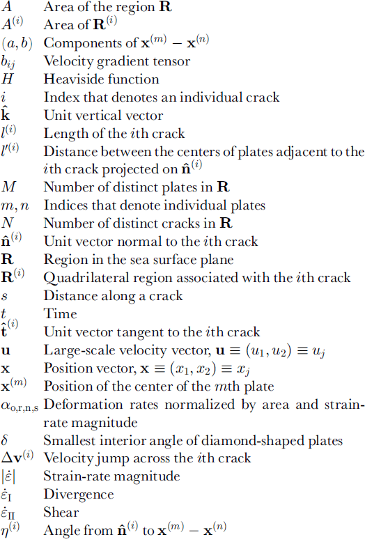
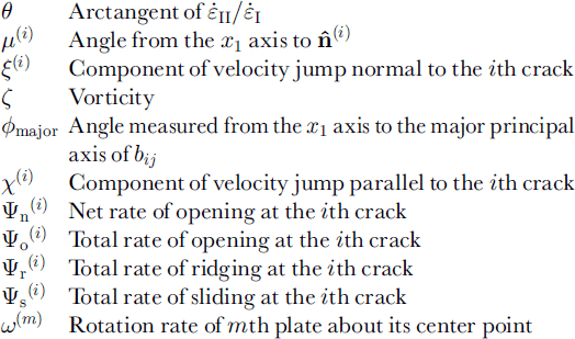
Notation
1. Introduction
Usually pack ice does not exist as a single sheet. Instead, it is the aggregation of many pieces, called plates, that vary in size and shape. If the plates are in contact, pack ice can be viewed as a sheet with many cracks. If they are spaced widely, the pack resembles a two-phase medium. In this and the following paper (Reference Ukita and MoritzUkita and Moritz, 2000) we use the term ˚plate" to designate a rigid element in the field of motion of pack ice, and the term ˚crack" to designate the boundary between adjacent distinct plates. These kinematically defined terms are distinguished from the familiar terms ˚floe" and ˚lead" that describe the morphology of the pack ice. This convention facilitates precise analysis of the ice kinematics and deformation, without limiting the possible relationships between kinematics and morphology. In real pack ice, the elements identified morphologically as floes and leads sometimes coincide with plates and cracks, and sometimes do not.
In response to forcing by winds and ocean currents, the plates exhibit a variety of motions that change on a wide range of time-scales. By definition, individual plates move as rigid bodies. The pattern of ice velocity in a large region, which is called the large-scale ice motion, is defined by the set of rigid-body motions of all plates within that region. In this view, cracks are defined as the locus of points on which the ice velocity changes discontinuously from the rigid-body motion of one plate to that of another.
In real sea ice, cracks may be elongate regions of small but finite width along the edges of plates. Within these regions the ice bends, breaks, piles, slides and separates. We model these cracks as curves, based on their small area compared to the plates. It is plausible that geometric patterns associated with cracks affect the large-scale relationships among velocity, deformation and external forces. Particularly important aspects of ice deformation are the production and loss of new open-water area and the production of ridged ice. Locally these processes depend on the component of relative motion of adjacent plates normal to the cracks. Due to the rapid air-sea transfers of heat, radiation and moisture over open water and thin ice, knowledge of opening, closing and ridging processes is essential for understanding the surface energy and mass balance. The energy transformations and horizontal forces associated with ridging play a fundamental role in theories of large-scale sea-ice rheology as well. For this latter topic, sliding motions parallel to cracks may be important too.
Large-scale theories for the mass and momentum balance describe opening, closing and ridging as functions of a continuous and differentiable velocity field. For example, the sea-ice thickness distribution theory (Reference Thorndike, Rothrock, Maykut and ColonyThorndike and others, 1975, henceforthT75) models the rates of opening and ridging (per unit area) as functions of the divergence and shear of the large-scale velocity field. These quantities are invariants of the large-scale strain-rate tensor. The shape of the yield curve needed to close the large-scale momentum equation may be determined by the ridging function, based on a hypothesized relationship between energy transformations caused by mechanical redistribution of ice thickness and work done by the large-scale stress tensor (Reference Parmerter and CoonParmerter and Coon, 1972; Reference RothrockRothrock, 1975; Reference HiblerHibler, 1980). Because this hypothesis introduces unknown functions and parameters, it is difficult to test by comparison with observations. This situation poses important questions: What is the relationship between the discontinuous, piecewise-rigid pattern of motion realized by a set of plates, and the continuous, differentiable large-scale velocity field? How do opening, closing, ridging and sliding depend on the large-scale strain rate, and its small-scale manifestation as rigid-body motions of plates? Only the discontinuous pattern can be observed directly, and it would seem to depend on the geometric pattern of cracks.
Reference ThorndikeThorndike (1987) investigated such questions with the aid of a random-geometry model. Cracks are distributed isotropically on the plane using a Poisson distribution for distance from the origin and a uniform distribution for crack orientation. The normal component of the velocity difference on a crack is modeled as an independent Gaussian process.
Observations, especially of gray-tone curvilinear features on satellite images, suggest that crack patterns in real sea ice usually exhibit preferred orientations (e.g. Reference Shapiro, Burns, Weller and BowlingShapiro and Burns, 1975; Reference Marko and ThomsonMarko and Thomson, 1977; Reference Kupetskii and TimokhovKupetskii, 1984; Reference Vinje and FinnekasaVinje and Finnekåsa, 1986). Reference ErlingssonErlingsson (1988) showed that the existence of preferred crack intersection angles is consistent with a constant angle of internal friction in a material that satisfies a simple Mohr-Coulomb yield criterion. Reference Schulson and HiblerSchulson and Hibler (1991) suggested that a single mechanism may account for crack patterns over a wide range of spatial scales. Reference Coon, Knoke, Echert and PritchardCoon and others (1998) presented elements of a rheological framework that recognizes anisotropies associated with frozen leads within a continuum element of pack ice. There is relatively much less direct information on the geometry of cracks defined as locations of discontinuities of velocity (Reference Hall and RothrockHall and Rothrock, 1981). Overall, satellite data do suggest that a uniform distribution of crack orientations is unrealistic in many cases.
The goal of this presentation is to define the geometric and kinematic parameters that describe deformation of the pack ice in such a way that the relationships between the motion of rigid plates and the deformation can be evaluated. Toward this goal, we develop a kinematic model whose inputs are the large-scale strain rate and the geometry of cracks, and whose output is the discontinuous piecewise-rigid field of motion of the plates. From the latter field, the large-scale opening, ridging and sliding rates are computed directly. Using this model, we investigate the dependence of ice deformation on the geometry of cracks in a framework wherein each piecewise-rigid velocity field is well defined, realizable and self-consistent.
2. Background
In T75, it is argued that isotropic behavior follows from a uniform distribution of crack orientations, and that this uniformity might be realized if the pack is fractured by cracks that originate through processes independent of the large-scale stress. Examples of such processes are thermal stresses and isostatic imbalances. A different view is that the distribution of crack orientations is non-uniform, exhibiting preferred directions. Crack directionality might be determined by various factors, such as boundary conditions at a coast, and spatial gradients of ice thickness, ice concentration and temperature. Nevertheless, it is plausible to hypothesize that any crack-orienting factor must manifest itself through the action of the large-scale stress whose orientation is characterized by the principal direction of the stress tensor (e.g. Reference Marko and ThomsonMarko and Thomson, 1977; Reference ErlingssonErlingsson, 1988). For isotropic materials, the principal axes of stress and strain rate are aligned (Reference HillHill, 1960). In the absence of direct measurements of large-scale stress, we focus here on relationships between the crack orientation and the principal axis of strain rate.
Even if cracks exhibit preferred orientations that are related closely to the principal axis of strain rate, one cannot rule out the model of pack ice as a material fractured by small-scale mechanisms such as thermal cracking. A large-scale stress might simply impose directionality by organizing pre-existing, uniformly distributed, small-scale fractures to produce longer, interconnecting lines of velocity discontinuities (i.e. cracks) that leave many of the small-scale fractures inactive. The alternative view is that kinematically observed cracks represent single fractures of a solid sheet that occur in response to, and in a direction consistent with, the large-scale stress tensor acting at the time of failure.
With non-uniform orientations either by pre-existing cracks or by active cracks, one expects opening and ridging to depend on geometry because the major principal axis of the strain-rate tensor defines a particular direction in the plane. Cracks oriented perpendicular to this direction might be expected to experience maximum opening and minimum ridging, and vice versa for cracks oriented parallel to this direction. These considerations suggest that the relationships between ice deformation and strain rate will depend on the orientation of the cracks measured relative to the principal axis of the strain rate. To extend this idea from intuition to quantitative results, one must take into account the orientation of cracks relative to the velocity jump across the crack, and the dependence of these quantities on the large-scale velocity gradient. This requires, in addition to the orientation of the crack with respect to the principal direction of the strain rate, another geometric parameter to describe the orientation of the crack relative to the vector between the geometric centers of the rigid plates on opposite sides of the crack.
3. The Kinematic Model
3.1. Geometry of cracks and plates
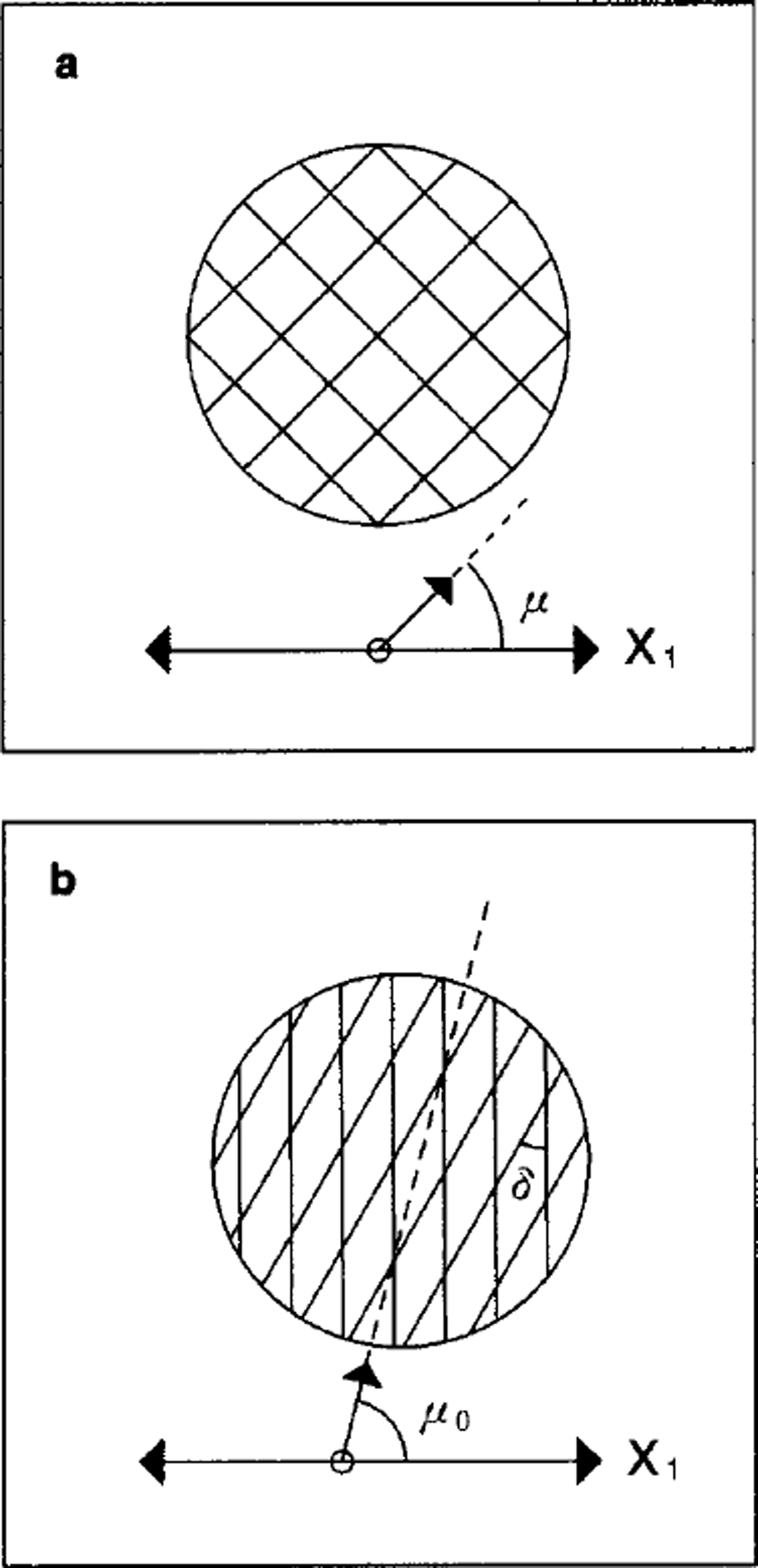
The geometry of the ice cover is determined here by a partition of a region R of the sea-surface plane into discrete, non-overlapping plates. Let the area of this region be A. If A is sufficiently large, the region contains many ice plates and we refer to physical quantities averaged over A as large-scale variables. Each plate is bounded by a closed curve. The plates are closely packed, with no open water between them. In other words, the ice concentration is 100% and the boundary of each plate is everywhere in contact with the boundaries of adjacent plates. Geometers refer to partitions of this kind as tilings of the plane. The tiles correspond to individual plates. For simplicity, this analysis is limited to tilings of convex plates. It follows that each plate is a polygon, and the plate boundaries become sets of straight-line segments. Each distinct line segment is called a crack. Figure 1 shows two examples of tilings of convex polygons. The patterns of squares and diamonds are uniform tilings, because all plates are identical. The regular tilings, a subclass of the uniform tilings distinguished by reflective symmetry of the tiles, are three in number: uniform squares, uniform hexagons and uniform equilateral triangles. A useful property of regular tilings is that each crack is perpendicular to the line segment joining the centers of the two plates adjacent to the crack.
(a) Uniform square plates and (b) uniform diamond plates with the smaller interior angle S. For the square case, μ measures the orientation of one set of sides. For the diamond case, μo measures the orientation of vertices with the smaller angle. Both angles are defined with respect to the major principal axis x1
If the large-scale area A, the total number of distinct plates M and the total number of distinct cracks N are finite, then each plate may be identified by an index m = 1, M, and each crack may be identified by an index i = 1, N. Because the plates are convex polygons, there is a one-to-one correspondence between pairs of plates indices (m,n) and the crack index i : (m, n) ― (i). Let × = (x1,x2) =
Xj
be the position vector of a point in the plane, where boldface type denotes a two-dimensional vector, subscripts denote the components of a vector, and the tensor subscript j may take on the values 1 and 2. On a given crack (Fig. 2), let x(s) be the position of a point parameterized by its distance s from the end of the crack. The length of the ith crack is
 Here and henceforth, superscripts in parentheses denote individual cracks or plates. Let
 and
 be unit vectors normal and tangent to the crack. So defined,
 and
 are determined up to a rotation by π. TO determine these vectors uniquely, let × (m) and X(n) be the positions of the geometric center points of the mth and nth plates whose mutual boundary is the ith crack. The relative position vector × (m) ― × (n) plays an important role in the analysis of opening, sliding and ridging on the ith crack. Define the unit normal vector
 so that it points towards the interior of the plate m whose position × (m) appears first in the expression for the relative position vector, and let
 point 90° to the left of
 It follows that the normal component of the relative position vector is positive:
 Referring again to Figure 2, we see that a unique region R (i) of area A(i) = l(i)l′(i)/2 may be identified with each crack. This region corresponds to a pair of triangles sharing a common base whose length is l(i). The vertices of the triangles are the ends of the ith crack and the respective geometric centers of the adjacent plates. By this construction, the set R(i), i = 1, N is a dual of the original tiling of plates, and therefore constitutes another tiling of the plane. This fact is useful in defining large-scale variables that are normalized to unit area A(i)/A The weighting factor associated with each crack is the normalized area which sums to unity, and can be identified with the probability of the given crack.
Definitions of geometric quantities used in the text (a) for a region defined by two plates and (b) for a quadrilateral region defined by a crack and two centroids.

The geometry of each crack may be specified by its length l(i) and two angles for tilings of convex plates. Let X(m) – X(n) ≡ (a,b) and
 (Fig. 2). μ(i) is thus the angle measured from the x1
axis to the vector normal to the ith crack. Let η(i) be the angle measured from
 It follows that


and

Because
 points toward
 is positive.
3.2. Large-scale motion
The large-scale motion of the pack ice is defined by a velocity field u(x) that is differentiable in space. We may think of this field as the velocity pattern determined by smooth fields of surface winds and ocean currents, acting on an ice cover whose properties are specified statistically so that they too vary smoothly in space. The large-scale velocity vector is denoted ω = (Ul,u2) = uj.6 The relative motion of points sufficiently close to an arbitrary origin varies linearly with position

where the velocity gradient at the origin is a second-order tensor

and summation is implied over repeated subscripts. The angle,

measured from an arbitrary x16 axis, defines two directions in the plane, the major and minor principal axes of the velocity gradient. If we choose coordinates such that the x1 axis coincides with the major principal axis of bij then ømajor=0and we have

where


and

The respective terms on the righthand side of Equation (7) describe an isotropic (non-deviatonc) expansion or contraction, a stretching along x1
with an equal compression along x2
and a uniform rotation. Because the uniform translation ui(0) and the rotation (/2 do not change the distance between any two points on the ice, we assume that they do not contribute to the instantaneous rates of opening, ridging and sliding, and henceforth we set
Ui(0) = 0 and ζ = 0. Together the remaining quantities define the strain rate whose invariants are called divergence
 and shear
 and whose major principal axis is in the x1
direction.
 measures the magnitude of the strain rate andtf measures the ratio of shear to divergence. The values
 correspond to pure divergence, uniaxial stretching, pure shear, uniaxial contraction and pure convergence, respectively.
To summarize, the portions of the large-scale velocity field relevant to the instantaneous rate of ice deformation at any point × may be written as

where × = (x1,x2) correspond to the principal axes of the velocity gradient.
3.3. Deformation on a single crack
The deformation of the ice cover is determined here by the relative motion of adjacent plates. On each crack we evaluate the rates of opening, ridging and sliding. Opening is defined as the rate of change of the area of open water, expressed as a fraction of the total area. Similarly, ridging is defined as the fractional rate of change of the area of overlapping ice, produced by the normal component of relative motion at the crack. Finally, sliding is defined as the absolute value of the tangential component of velocity difference across a crack, integrated over the length of the crack.
Let v(x) denote the piecewise-ngid velocity of the ice at position × on a given plate. At each point s along the ith crack, the velocity jump across the crack is
 where superscripts m and n distinguish the two sides of the crack. Now resolve the velocity difference into components normal,

and parallel,

to the crack at s. The normal component makes a contribution ξ(i)(s) ds to the rate of change of open-water area or overlapping ice area over a small increment ds. The contribution is opening when positive, and ridging when negative. Therefore, in dimensional form we may express the total opening as the line integral over the length of the ith crack:

the total ridging as

the net opening as

and the total sliding as

where H(x) is the Heaviside function. According to Equation (19a), sliding occurs on any crack where there is tangential motion. If the definition of sliding is limited to cracks that are not opening, then

By definition,
 and
 are non-negative.
In T75 the large-scale deformation is described by the non-dimensional coefficients σ0
for opening and στ for ridging. The quantities defined above, which may be denoted collectively by
 refer to a single crack i, and have dimensions area per unit time. For consistency with the notation of T75 we define corresponding non-dimensional coefficients for the ith crack as follows:

Summing over all cracks in a large-scale element of the pack ice, the large-scale coefficients of deformation become

3.4. Velocity jump on a single crack
To develop formulae for each coefficient of deformation that depends on 9, on the rotation rate of individual plates <>) and on the geometric properties of the cracks in R, we need the velocity difference across the cracks Δv(i)(s). To this end, we introduce a simple model that determines the rigid-body velocity v on individual plates as a function of the positions of the plate centers, the large-scale velocity gradient Vu and the rigid-body rotation of each plate.
The velocity of the mth plate, moving as a rigid body in the plane, may be specified as the sum of the translational velocity v(m) at the geometric center × (m) of the plate and a uniform rotation ω(m) about the center point. Note that <>) is a property of the motion of a plate, which is distinct from the vorticity ζ of the large-scale field of motion, making the total rate of rotation (/2 + ω (m) Then for any point × on the mth plate,

where
 is a unit vertical vector. The velocity difference across the ith crack between the mth and nth plates becomes

The simplest relationship between the translational motion of plates, the geometry of the cracks bounding the plates and the large-scale strain rate is realized by setting the velocity of the plate center equal to the large-scale velocity evaluated at the geometric center of the plate:

To find the translational part of the velocity difference, we substitute the position difference between plates m and n on either side of the ith crack to obtain

Because the large-scale velocity gradient provides no information about spatial differences in angular velocity, the simplest model of plate rotation is to specify a uniform rotation rate
 for all plates. In nature, the rotation of individual plates probably depends in a complicated way on the geometry of the plate and the motion of adjacent plates, but this complication is beyond the scope of the present analysis. With uniform plate rotation, the terms involving x(s) cancel in Equation (23), leaving

With polygonal and uniformly rotating plates, the integrands in Equations (16–19) are constant along the entire length of each crack, and we have so that we may write

where we have used Equations (16), (20) and
 Similar expressions hold for the ridging, net
 opening and sliding on the ith crack. The expressions for all involve the quantity

making use of Equations (1–3). Taking the dot product of this expression with the unit vectors
 and
 and simplifying the trigonometric terms, we obtain

and

respectively.
3.5. Large-scale deformation
To obtain large-scale deformation coefficients, we simply multiply by the crack length l(i) sum over all cracks and normalize with the area and the strain-rate magnitude in accordance with Equations (20) and (21). For opening we have

and for sliding

where
 The expression for the ridging coefficient στ is obtained by substituting H(i) ― 1 for ff≈ in Equation (31).
Several features of Equations (31) and (32) are worth noting. The large-scale coefficients of deformation have been formulated explicitly in terms of
 and the geometry of cracks. The coefficients of cos θ, sin θ and
 are sums of trigonometric functions of the angles μ
(i) and η(i) associated with the orientation of cracks and with the vectors between the centers of adjacent plates. The sums are taken over all cracks in the large-scale region R The contribution of each crack is proportional to the fractional area A(i)/A, which depends on the length of the crack and on the normal component of the relative position vector connecting the centers of adjacent plates. The Heaviside functions assure that only those cracks that are opening contribute to the opening coefficient α0, and vice versa for the ridging coefficient αr. Because the argument ξ of the Heaviside function depends on 9, the coefficients of cos θ and sin θ are functions of 9.
In this kinematic model, the angles μ (i) and η(i) may be specified independently. η(i) is determined purely by the geometric pattern of cracks, whereas μ (i) depends on how these cracks are oriented with respect to the principal axis of the strain rate. The magnitude of the term tan η(i) grows without bound as η(i) → ±π/2, corresponding to a crack oriented parallel to the vector × (m) ― × (n) between the centers of adjacent plates. In this limit, the horizontal extent of individual plates is unbounded, and we no longer have a tiling of the plane. For tilings of the plane that produce bounded plates with very large aspect ratio (i.e. long, thin plates), the tan η(i) terms are large but finite. In this case, these terms contribute large amounts of opening and ridging (1) if the plates are rotating (ω ≠0), and (2) if the large-scale motion is shearing (sin θ ≠ 0) in a direction that is neither parallel (μ(i)6 = π/2) nor perpendicular (μ(i)6 =0) to the cracks.
The net opening αn = α0 ― αr is found by substituting 1 for ff≈ in Equation (31):

By construction, σn is the normalized time rate of change of the total area A of the region R that contains the N cracks. That is,

Because the large-scale velocity is a continuous, differentiabl field, the corresponding large-scale rate of area change associated with the large-scale velocity field is:

Equality of these would imply that

placing a constraint on the geometric quantities

that would hold for any pattern of cracks. Because the geometry is specified independently of
 and ω, we may set ω = 0 to obtain

and
 to obtain

Mathematical proofs of constraints equivalent to Equations (38) and (39) are given in Reference MilesMiles (1964), for the expected value of the trigonometric functions, evaluated over an ensemble of random tilings with isotropic statistics. We know of no proofs that Equations (38) and (39) are satisfied for an arbitrary tiling of the plane, with finite or infinite N. In section 4, we show that these constraints hold for some uniform tilings that may be analyzed directly. We have explored whether additional geometric constraints are imposed by the expression for sliding, but thus far we have not been able to derive any such constraints by relating the known properties of the large-scale velocity to the rates of change of area or length in our discontinuous model.
4. Tilings of Uniform Plates
We are now in a position to evaluate the dependence of the coefficients of deformation on the geometry of cracks, by using Equations (31–33) with specific values of μ (i) and η(i) that correspond to particular geometry of the plates. The simplest problems are formulated with uniform tilings in which every plate has the same size, shape and orientation.
4.1. Uniform square plates
For a tiling of uniform squares of side L (Fig. la), there are only two distinct values of α 0 (i), corresponding to any two adjacent sides of the square. By symmetry, we can derive results valid for the complete tiling by studying only these two sides. On the two distinct cracks we have: COS 2μ(1) = ― cos 2 μ (2), η(i) = 0, l’(i) = l(i) = L, A(1)+A(2) =A = L2, and A(i)/A = 1/2, i = 1, 2. Thus Equations (31–33) become


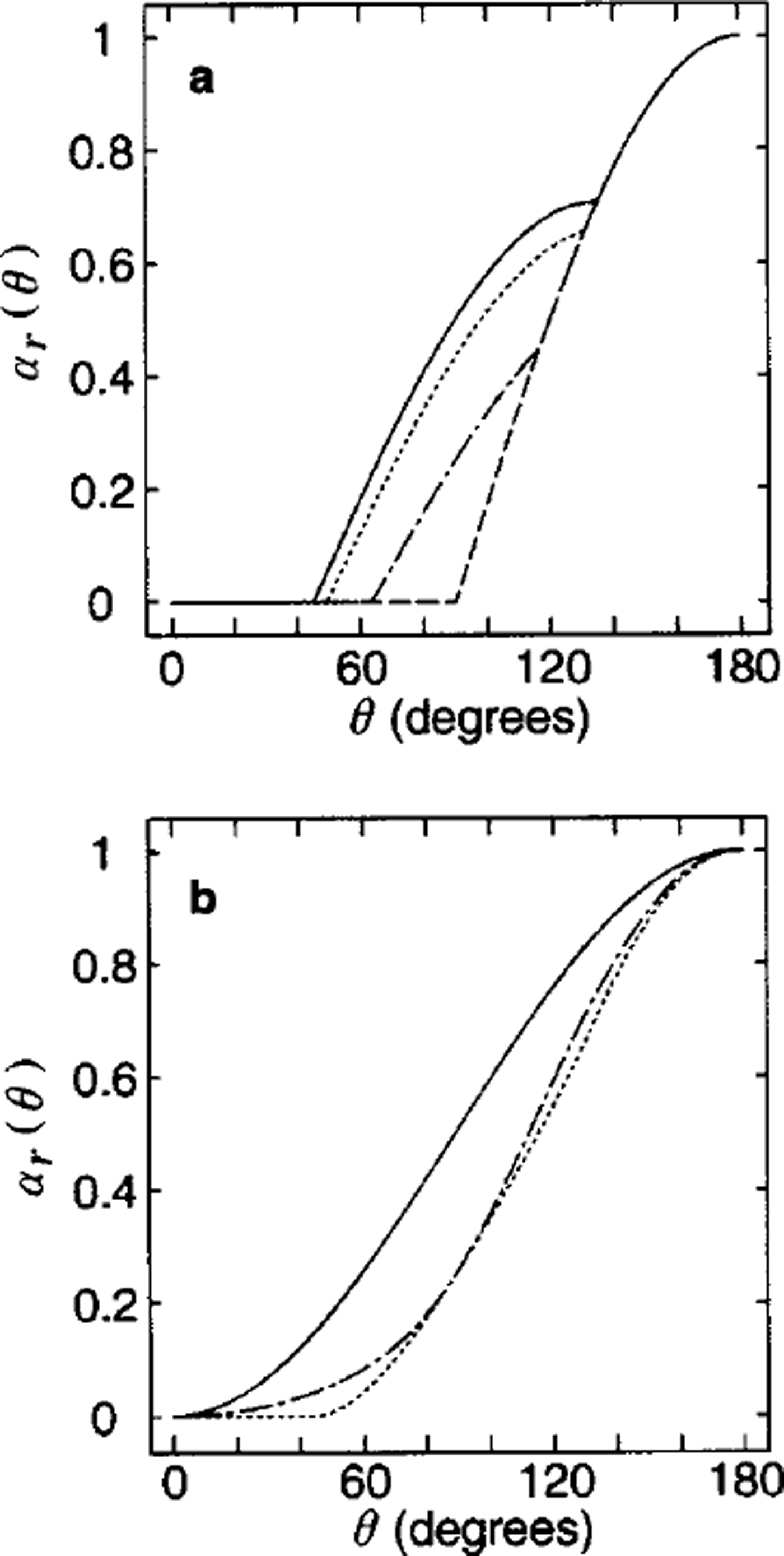
By symmetry, only the range 0 ≤ μ(1) ≤ π/4 needs to be considered. Direct substitution shows that Equations (38) and (39) are satisfied, and thus we compute the ridging coefficient as αr = α0― cos θ. The ridging coefficients shown in Figure 3a are independent of plate rotation w. In general, if/*≈ is given, there are three distinct intervals for opening and ridging on 0 ≤ θ ≤ π. In the first interval 0 ≤ θ ≤ θ1
both Heaviside functions are equal to one, i.e. both cracks are opening. In the second interval,
 so the first crack is opening and the second crack is closing. In the third interval, θ2 ≤ θ ≤ π, both Heaviside functions vanish and the opening is zero. Thus we have


where the intervals are determined by


Note that the maximum of (cos θ,0) and the maximum of (–cos θ,0) are the opening and ridging due solely to the divergence, respectively. Therefore, for all 0, the opening and ridging coefficients α0 and αr equal or exceed the portion associated with divergence. The additional opening and ridging arise from the velocity shear, which appears only on the middle interval θ1 ≤ θ ≤ θ2. Therefore, the additional ridging is at its minimum when the angle μ(1) is chosen such that 0! = 02. This minimum occurs with / μ (1) = π/4. The maximum opening and ridging occur with / μ (1) = 0. Between these extremes, there is a family of opening and ridging curves corresponding to different choices of / μ(1) (Fig. 3a). For comparison, the ridging curves presented by T75, Reference RothrockRothrock (1975) and Reference HiblerHibler (1979) are shown in Figure 3b.
(a) The ridging coefficients as afunction of the shear-to-divergence ratio, θ,for different values of μ. 0° (solid line), 15° (dotted line), 30° (dash-dotted line), and 45° (dashed line) under the uniform square geometry. Note that at μ6 = 45° the contribution from the shear part is minimized, whereas it is maximized at ,1=0°. (b) The ridging coefficients that have been proposed in the past. T75 (solid line), R75 (dotted line) and H79 (dash-dotted line) correspond to the circular (Reference Thorndike, Rothrock, Maykut and ColonyThorndike and others, 1975), the teardrop (Reference RothrockRothrock, 1975) and the elliptical (Reference HiblerHibler, 1979) yield-curve shapes.
The total sliding depends on both strain rate and plate rotation, as follows:

If shear dominates over plate rotation, then the rotation adds to the sliding on one crack and subtracts from the sliding on the other crack, so the net contribution of rotation is zero. If rotation dominates over shear, then the shear makes no contribution for the same reason. Sliding coefficients for uniform squares with shear dominating are plotted in Figure 4a. Sliding increases with the shearing strain rate sin 0 to a maximum at θ = π/2. For all values of 0, the minimum and maximum sliding are realized with crack angles μ(1) = 0 and μ(1) = 45°, respectively. These crack angles correspond to extrema of the opposite sense in ridging: crack orientations that maximize sliding minimize ridging and vice versa. The effect of plate rotation is to introduce two intervals along the θ axis on which the sliding has a constant, non-zero value. If sliding is assumed to occur only on closing cracks (Equation 19b) we find the curves shown by the various kinds of dashed lines in Figure 4b. For each orientation μ, a portion of the curve coincides with the solid curves, but discontinuities occur at values of θ where one of the cracks changes from opening to closing.
(a) The sliding coefficients as a function of the shear-to-divergence ratio, θ, for different values of μ,0° (solid line), 15° (dotted line), 30° (dash-dotted line), and 45° (dashed line) under the uniform square geometry. In this case, all crack segments are sampled, corresponding to Equation (19a). (b) The same except based on only closing segments, corresponding to Equation (19b). Mote that for both cases it is minimized at ,1 = 0°.
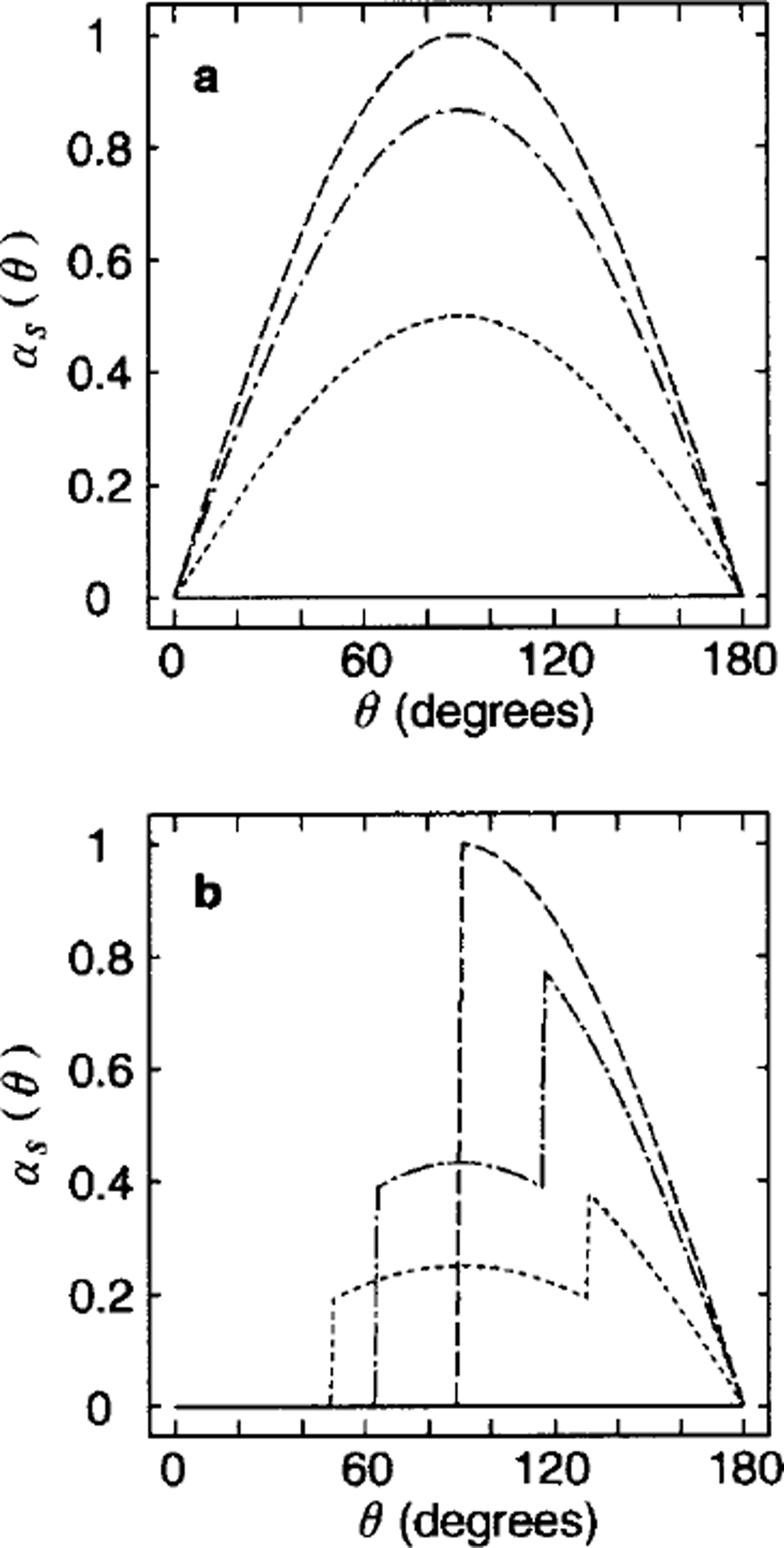
To summarize, the regular tiling of squares illustrates how the general model embodied in Equations (31–33) can be applied to address the relationship between ice geometry and deformation. For all values of μ(1), the resulting coefficients produce less ridging than those employed by T75. The value μ(1) = π/4 minimizes the opening and ridging, and the value μ (1) = 0 minimizes the sliding. The opening and ridging coefficients satisfy the area conservation constraint (Equation (36)).
4.2. Uniform diamond-shaped plates
The uniform square tiling studied above was chosen primarily for its simplicity and illustrative purposes. Observations of lead and crack patterns in sea ice show that although real plates do not constitute such a tiling, repetitive patterns of cracks do occur. For example, Reference Marko and ThomsonMarko and Thomson (1977) and Reference ErlingssonErlingsson (1988) found a preponderance of diamond-shaped plates in their analyses of satellite images, and suggested that the smaller of the interior angles at the apex of the diamonds tends to be approximately 30°. Based on simple rheological models, these authors argue that the principal axis of stress must bisect one of the interior angles of the diamond at failure. Therefore, if the pattern of cracks results from stresses that satisfy an isotropic rheology, the diamonds must align symmetrically with the principal axes of strain rate at failure.
A tiling of uniform, equilateral diamonds (Fig. lb) requires an additional parameter that specifies the shape of the plate, taken here to be δ, the smaller of the two interior angles. There are two distinct cracks associated with the diamond, whose orientations are μo ± δ/2, respectively, where μo defines the orientation of vertices with the smaller interior angles with respect to the major principal axis. Then on the basis of the symmetric argument, we have for i 1, 2, A(i)/A = 1/2, μ(1) = / μ0 + δ/2, μ(2) μo ― δ/2, η(1)= π/2 ― δ and η(2) = _ π/2 + δ. Note that for uniform diamonds, η(i) is generally non-zero unless δ = π/2 (the uniform square case). Also the coefficients of the terms involving ω are not necessarily equal and opposite because of the Heaviside functions. Here for simplicity we set ω = 0.
Figure 5a shows the ridging coefficients for the diamonds with δ = 30° for a range of the vertex orientations, μ0 = 0, 15, 30, 45 degrees. When an axis of symmetry of the diamonds (either with larger or with smaller interior angles) forms a 45° angle with respect to the principal axis of the strain rate, μ0 = 45, the ridging coefficients are maximized (solid line in Fig. 5a). This is consistent with the square geometry case as it is a special case with μ0 =45 and δ = 90. Likewise the ridging coefficients are minimized when an axis of symmetry of the diamonds is parallel to the principal axis of the strain rate. The ridging coefficients take the same value for μ0 = π/4 ± d with 0 ≤ d ≤ π/4, implying the symmetry at μ0 = 45. The range of 0 ≤ μ0 ≤ π/4 thus covers all cases for the ridging coefficients. This is in contrast with the wider interval, 0 ≤ μ0 ≤ π/2, that is necessary to cover all possible sliding coefficients (see Fig. 5b).
The ridging coefficients (a) and the sliding coefficients (b) as functions of the shear-to-divergence ratio, 9, for different values of μ0 under the uniform diamond geometry (30° as the smaller interior angle). For (a), μo = 0° (dashed line), 15° (dash-dotted line), 30° (dotted line), and 45° (solid line), whereas for (b), μo = 0° (dashed line), 30° (dotted line), 45° (solid line), 60° (dash-dotted line), 90° (dashed line with small breaks). Note that for the ridging there is a symmetry with respect to μo at 45°, but not for the sliding
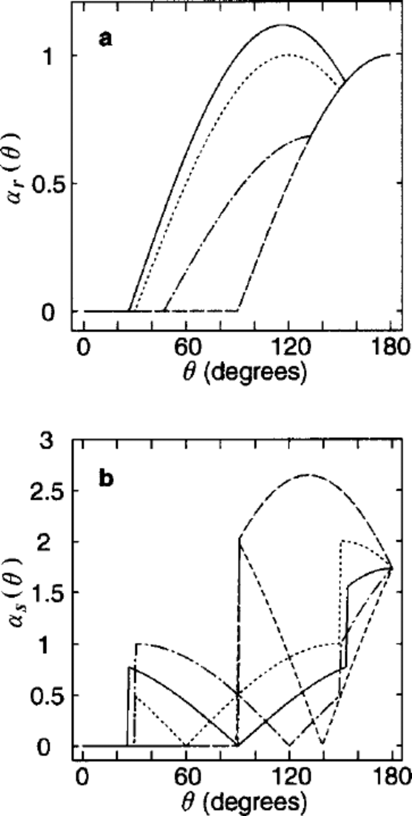
These curves, together with Figures 3 and 4(δ = 90°), illustrate how the geometry of the plates and cracks affects the deformation coefficients. For diamond-shaped plates, the ridging coefficient has a unique minimum for all 9, given by

And in each case, the minimum ridging is achieved when μ is such that a vertex of the diamond is aligned with the principal axis of the strain rate.
The tiling of uniform diamonds demonstrates that different combinations of plate shape and orientation can produce the same opening and ridging. For example, let μ be the orientation of one side of a tiling of uniform squares, and
 be the orientation of one side of a tiling of uniform diamonds with interior angle δ. Then in the middle interval of θ where shear motion contributes to ridging, using Equations (31), (43) and (44), we obtain identical opening and ridging coefficients for diamonds and squares by choosing ,5 such that

By contrast, the sliding functions for different diamond-shaped plates are distinct, due to the dependence on cos 9 (see Equation (32)), which introduces an asymmetry on the θ axis. Therefore, although our model produces a unique set of deformation coefficients for any given crack geometry, the inverse does not hold: different geometries may correspond to the same deformation coefficients. To address this issue with observations, we need to estimate the crack orientation from satellite imagery, simultaneous with the estimates of strain rate, opening and ridging for testing the present model.
4.3. Ensemble of uniform squares with different orientations
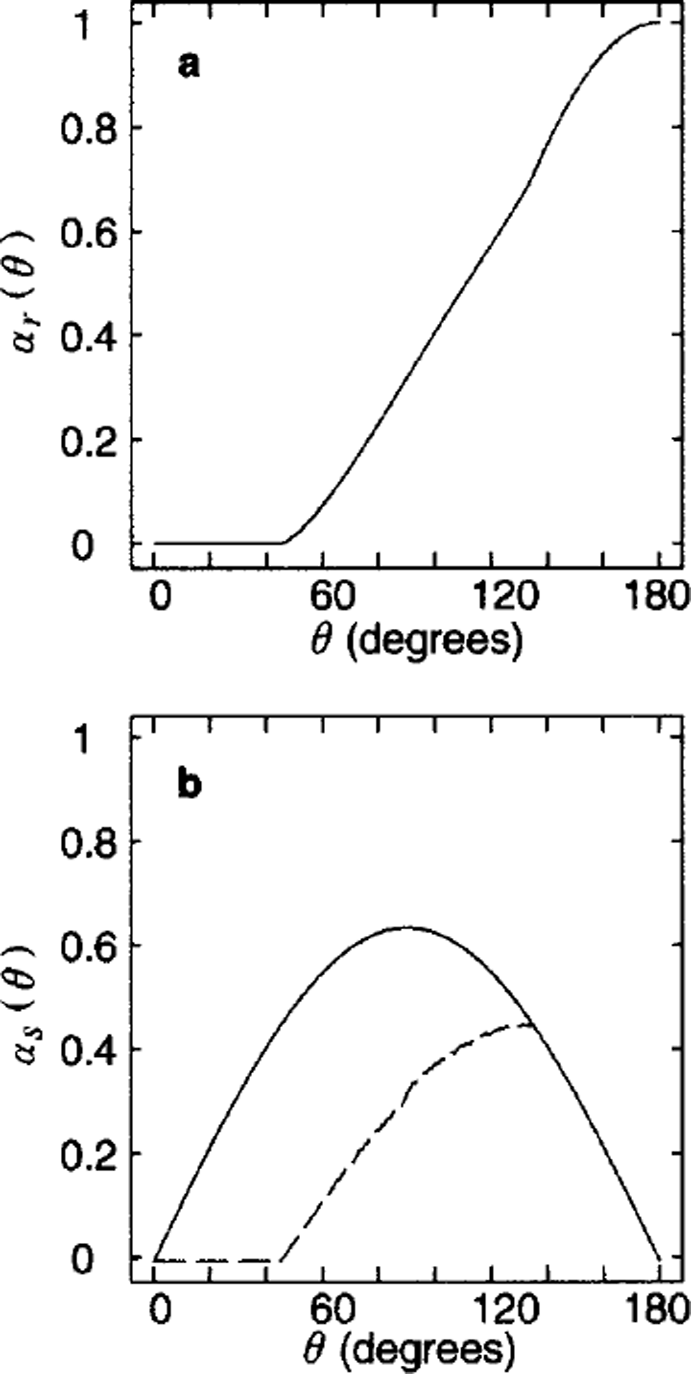
The simple geometry of uniform square plates may be used to investigate the isotropic geometry case by considering an ensemble of realizations. In each realization, the plates are uniform squares with an orientation μ(i). In the ensemble of all realizations, / μ(i) is distributed uniformly on (0, π/4), thus making this an isotropic representation. The deformation coefficients are computed by averaging over all realizations. The cracks in the ensemble have no preferred orientation. Averaging the ridging coefficient over this ensemble produces the curve shown in Figure 6a. This curve illustrates two points. First, with a continuous (uniform) distribution of crack angles μ, the resulting ridging coefficient is not of the form q1 cos θ + q2 sin θ on subintervals of 0. To see this, compare Figures 6a and 3a. Second, this explicit calculation with isotropic cracks again produces opening and ridging coefficients significantly smaller than those employed by T75, and of a shape more nearly like that of Reference RothrockRothrock (1975), Reference HiblerHibler (1979) and Reference Stern, Rothrock and KwokStern and others (1995). Figure 6b shows the corresponding sliding function for two cases, one with the closing constraint (lower dashed line calculated by Equation (19b)) and one without the constraint (upper solid line by Equation (19a)). Note that the former is symmetric about 0 = 90 and the latter is not.
The ridging coefficients (a) and the sliding coefficients ( b) as functions of the shear-to-divergence ratio, 9, under the uniform square geometry, averaged for uniformly distributed μ ∊ [0,π/4). For the sliding coefficients, the dashed and solid lines correspond to the cases with and without the closing constramt, Equations (19b) and (19a), respectively.
5. Concluding Remarks
We have developed a kinematic model on the basis of a piecewise-rigid motion field comprising plates and cracks. This model, though idealized, provides a means to investigate the relationships between the ice geometry, the large-scale opening, ridging and sliding coefficients and the large-scale strain rate. Simple geometries composed of square and diamond-shaped plates were used to show that the geometry of plates and cracks affects these relationships. From these cases, we found that the geometry of the plates and cracks affects these relationships. Specifically, the orientation of the cracks with respect to the direction of the principal axis of the strain-rate tensor controls the contribution to the coefficients by the shear motion. We also found that the calculated opening and ridging coefficients both with those simple geometries and with the ensemble of uniform squares with uniformly distributed cracks are similar to those hypothesized by dynamical theories such as Reference RothrockRothrock (1975), Reference HiblerHibler (1979) and Reference BratchieBratchie (1984), and one estimated from satellite observations (Reference Stern, Rothrock and KwokStern and others, 1995).
The model presented here is specified by quantities that are, in principle, observable. Perhaps, the most difficult task is to directly observe a piecewise-rigid-body motion by individual plates with sizes in the range 1–100 km. An indication by satellite images seems to support the conceptual model of rigid plates (see the presence of ˚blocks" in the ice motion in Reference Stern, Rothrock and KwokStern and others (1995)). Nevertheless, more observational studies are necessary to elucidate the role played by the crack and plate geometry in the ice deformation. Certainly, additional information about either the geometry of existing cracks or the actively opening cracks, simultaneous with that on the large-scale deformation, can be used to test the present model. A potential weakness of the present development lies in the simplicity of the geometries considered, the square and diamond-shaped plates. In the companion paper (Reference Ukita and MoritzUkita and Moritz, 2000), this limitation is to a large extent eliminated by considering the random geometry that simulates fields of pack-ice motion with prescribed statistical properties.
Acknowledgements
The authors would like to thank the U.S. National Science Foundation for their support under grant DPP-8705181 and the Office of Naval Research Arctic Program for their support under contract N00014–91–J-1377. Frontier Research System for Global Change is a joint program supported by the National Space Agency of Japan and Japan Marine Science and Technology Center. We thank D. A. Rothrock and A. S. Thorndike for useful discussions, M. A. Morales Maqueda and an anonymous reviewer for many useful suggestions for improving the text, and T. Mikami for her assistance in graphics.



