Nomenclature
- AIT
-
assembly, integration and testing
- ASAL
-
Algerian Space Agency
- CAD
-
computer-aided design
- CDS
-
Center for the Development of Satellites
- EDX
-
energy dispersive X-ray spectroscopy
- ESCC
-
European Space Components Coordination
- ITM
-
instrumentation metrology laboratory
- LMESM
-
electron microscope and materials science laborator
- LS1
-
LIoyd Instruments
- SEM
-
scanning electron microscope
- UAV
-
unmanned aerial vehicle
- USTO
-
University of Science and Technology of Oran
1.0 Introduction
The choice of electrical power contacts is a critical phase during the avionic system design, because they are responsible for transmitting high electrical power to enable the functioning of all subsystems installed in aircraft, unmanned air vehicles (UAV), satellites, electrical automotive or others domains requiring high power [Reference Holm1–Reference Domone8]. Electric connectors, which consist of two main parts (anode and cathode), are designed generally to be physically separated and easily plugged in a safe manner. Other aspects are also taken into consideration as design variables for aerospace applications, such as:
-
– Supporting satellite vibration during the operations (launch, separation phase, and orbiting) to avoid any partial discharge on the harness
-
– Limiting the vibration effects to avoid partial discharge on the harness during the aircraft/UAV flight
-
– Ensuring a large number of safe connection/disconnections during the assembly, integration and test phase (AIT)
-
– Ensuring a large number of safe connection/disconnections to cover maintenance and preparation for commissioning (drones, aircraft)
-
– Avoiding the partial discharge/disconnection caused by the embedded deployment system bootstrapping (solar generator, antenna…)
At the closed state of the connector, the electrodes are maintained in contact by a force applied initially to allow the passage of current. As this force is released, the conductive contact area will decrease, and the electrode contacts remain at a few spots, causing a significant increase in contact resistance. Since the same current must pass under these conductive contact points, this will cause the formation of hot spots and the ionisation of the contact area. When the contacts separate, an electrical arc is created between the electrodes. The current is now conducted by an ionised gas (plasma) where electrons move to the anode and positive ions move to the cathode [Reference Anthony9, Reference Kiffmeier, Önal, Austermann and Frei10].
In high-power circuit, the electrical arc has a high energy and temperature; the phenomena can damage the contact surfaces and cause their dysfunction by erosion, melting, corrosion and electrical insulation of the contact surfaces after several opening-closing operations [Reference Ou, Nakayama, Zen, Takeuchi and Yasuoka11–Reference Ramzi16]. The electric arc has other negative consequences affecting relays and electric circuits of electronics equipment [Reference Roman and Frank17] and photovoltaic cells [Reference Wang18, Reference Flicker and Johnson19]. This can also increase the electrical contact resistance [Reference Slade15], and it may also be responsible for fires [Reference Keller, Bailey, Wojtek Przytula and Jordan20, Reference Landfried, Savi, Leblanc and Teste21]. Moreover, the arc can be used for welding [Reference Navarro-Crespin, Lopez, Casanueva and Azcondo22], cutting [Reference Wang, He, Yu and Yang23], furnaces [Reference Hariyanto, Nurdin, Casanueva and Alvin Tanthio24], lighting [Reference Chang, Yang, Chan and Cheng25], producing carbon nanotubes [Reference Kundrapu, Levchenko, Ostrikov and Keidar26] and as propulsion for satellites [Reference Huang, Pan and Wu27].
The electrical arc can be mitigated using various techniques, such as applying an external magnetic field [Reference Vassa, Carvou, Rivoirard, Doublet, Bourda, Jeannot, Ramoni, BenJemaa and Givord28, Reference Kiryu, Tanaka, Seki and Satou29], increasing the contact opening speed [Reference Sallais, Carvou and BenJemaa30], altering electrode materials [Reference Yoshida, Sawa, Suzuki and Takaya31] and modifying the gas environment [Reference Grogg and Scharnk32]. While these techniques are well known, certain aspects of arc behaviour remain unclear and require further investigation [Reference Hasegawa and Tokumitsu33]. The movement of the arc is highly complex; at present, no universally accepted model can fully explain it [Reference Kharin, Nouri and Miedzinsky34].
The arc parameters that characterise the arc directly affect the number of cycles that a connector can endure [Reference Øyvang, Fjeld, Rondeel and Hagen35, Reference Yoshida, Sawa, Suzuki and Takaya36]. A cycle refers to the number of open-close operations a connector can withstand before it becomes unserviceable. Prolonged arc duration leads to significant degradation and reduces the lifetime of the contacts [Reference Holm1, Reference Yoshida, Sawa, Suzuki and Takaya37]. This phenomenon is highly dependent on the material and coating of the contact surface, with the electrode material being a critical factor that influences the reliability and service life of the switching devices. It’s important to note that reaching the maximum number of cycles doesn’t necessarily indicate that the connector is damaged, but rather that the resistance has increased considerably.
2.0 Experimental methology and setup
2.1 Testing strategy
This study evaluates the performance of electrical contacts used in a moderately powered DC circuit (32 V), representative of power levels typically found in microsatellite systems. The tested materials, some of which have not been previously studies under similar electrical conditions, feature thin electroplated coatings on copper to enhance resistance stability, durability and cost efficiency. Gold and silver are standard choices, but their behaviour under extreme conditions remains insufficiently understood. Solid gold, while conductive, is expensive and prone to deformation.
Arc parameters (voltage, current, arc duration and extinction gap) will be measured during switching operations using 5 mm hemispherical contacts made from various pure and coated materials (copper, brass, aluminum, gold-coated copper, silver-coated copper). Arc power, arc resistance and arc energy will be derived from these measurements.
Material performance will be compared to determine the most resilient contact type. Surface erosion will be analysed using scanning electron microscopy (SEM) and energy dispersive spectroscopy (EDS), with photographic documentation supporting the findings.
2.2 Dimension and shape of contacts
The contacts analysed in this work are part of an aerospace technologies appropriation strategy to improve the electrical harness development; particularly those used for switching the battery modules that operate over a range of bus voltages (20-32 V).
In this context, the selected power contact specifications, such as physical and electrical characteristics, are inspired from the European Space Components Coordination (ESCC) generic standard n°3,401 (see Fig. 1) to manufacture the contacts to be tested. The contact dimensions specified correspond to the requirements set out in this generic ESCC specification.
The contact variants to be covered by test and analyse.

The contacts tested are not assembled in their final configuration on connectors as shown in Fig. 1; they are provided separately as presented in Fig. 2. They will subsequently be used after crimping to manufacture the connector assembly.
Figure 2 shows a type of contact, geometry, computer-aided design (CAD) model and their materials to be tested and analysed. The realised contact samples have a diameter D of ∼5 mm, manufactured with a conventional machine.
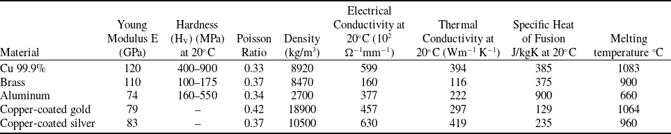
Various materials used and their mechanical, electrical and thermal properties [Reference Holm1, Reference Slade2]

A type of targeted contact for testing with different materials.

2.3 Contact materials properties
Table I shows the mechanical, electrical and thermal properties of used contact sample materials at the ambient temperature (20°C). Based on the industrial legacy, the selected materials have good thermo-electrical and mechanical properties and also by this choice, we covered both ranges of materials, pure and coated.
2.4 Design and implementation of the experimental test bench
This type of test requires a considerable investment in specific hardware to perform the experimental part; based on the experience acquired during the Algerian Space Agency’s (ASAL) AIT-satellite projects, and existing instruments and solutions available in the instrumentation and metrology laboratory (ITM) CDS-Oran, we proposed a homemade test bench (software/hardware), which is less cost-effective and able to cover the adopted test strategy.
The test to be covered consists of making contact between the two electrodes, the first connected to the generator ground and the second to the positive terminal. In order to set the operating voltage (in our case 32 VDC) and the required power (256 watts) relative to the target system (equipment, satellite or drones, etc.), a resistive load is used that emulates the system’s behaviour. The testing scenario will start with a direct contact between the two electrodes (facing each other), ensured by a light pressure between contacts; this is achieved by a modified traction machine (accessories and usage) to apply a pressure force in a direction to make the contacts closer to each other and to obtain the expected conduction between electrodes, thus simulating a male/female connector plug.
Next, the generator is switched ON, allowing the current to flow (8A), then the electrodes are separated in order to simulate a disconnection. During this operation, the phenomenon we’re investigating (the electric arc) is revealed. The duration of a complete test cycle (connection-disconnection-connection) is one second, which is systematically reproduced, as required, to study and analyse the phenomenon of the electric arc. The arc parameters (voltage, current, power) are recorded and automatically saved in CSV files according to the test procedures, then used by the software developed in Python to generate the results and analyses necessary for interpretation.
The expected scenario will be carried out as demonstrated in Fig. 3.
Trace of expected voltage and current (V arc , I arc ).

In Region (I), the two contacts are closed using initial force; in Region (II), represents the beginning of disconnection and the separation of the two contacts with the appearance of the electrical arc; and in Region (III), the total opening of the two contacts and the complete extinction of the electrical arc.
Figure 4 presents the symposium of the experimental setup used to measure the arc voltage and arc current (I arc and V arc ) of contacts with a tension of 32 VDC. The experimental setup is composed of two main parts: the first part is the mechanical system, and the second part is the electrical system.
Experimental bench for measuring arc voltage (V arc ) and arc current (I arc ).

2.4.1 Mechanical part
For this stand, we have used the precision machine ‘LIoyd instruments LS1’ allowing the opening-closing of electrical contacts continuously via a mobile traverse (Fig. 4). The anode is mounted on the bottom stationary jaw of the traction machine while the cathode is fixed in the top mobile machine jaw. The contact force is obtained by means of a force sensor with a precision of 0.01 N. During the test, the applied contact force Fc is equal to 20 N, the chosen opening speed vopen is 5 mm/s to reach an opening gap d is of 5 mm. The computer PC used is with Nexygen-plus application installed for control: the opening and closing speed, the contact force, the contact displacement and the opening gap.
2.4.2 Electrical part
The instrumentation and data acquisition part includes all the instrumentation that permits the automation of test and the continuous data acquisition. In this context, a stabilised ‘TDK-Lambda ZUP60-7’ power supply is used to tune the output voltage and current. The set supply voltage was 32 VDC with a current of 8A in order to obtain an input power of 256 watts. The used resistance load is equal to 4 Ω. A ‘Metrix is used monitoring voltage and current value during the opening Mx26’ multimeter-closing contact operations. To visualise and record collected data, a specific oscilloscope is used (Tektronix DP07104C), with large bandwidth (1 GHz) and maximum sampling rate (20 G sample/s) to track the evolution of the debited current and the voltage measured at the terminals of the contact after each opening. The data are recorded with a high sampling rate equal to 1M sample/s, allowing a precise measurement by a 1 µs sampling period. The arc current is measured based on the Hall effect with a current probe (500 MHz bandwidth and x10 attenuation) connected to a (Tektronix TCPA300) current probe amplifier (Fig. 4).
The arc current and arc voltage acquired during one contact opening operation were processed by scripts developed in Python to identify the needed parameters as the arc duration, arc length, arc power and arc energy for this operation; data acquisition continues during all the opening-closing operations.
2.4.3 Tests procedure
To guarantee that the tests are performed in conformity with the standards and regulations adopted by the Algerian space agency in CDS-Oran Laboratories, a test protocol has been elaborated to allow the test to be reproduced, covering the safety aspects and the reporting quality issued by the metrology service and the AIT department. Briefly, before accomplishing test steps are followed, the electrodes were cleaned with alcohol in order to remove all fat and dirt present on the contact surfaces. During mechanical preparation, the electrodes were mounted and aligned in the machine jaws. The electrical arc parameters (I arc and U arc ) were measured only during the contacts’ opening. The data acquisition of arc parameters only stops at the end of the contacts’ lifetime. It should be noted that the series of tests were carried out in laboratory at ambient temperature and atmospheric pressure.
3.0 Results interpretation and discussions
3.1 Result analysis
Following the protocol of test illustrated in Fig. 3, all contact tests were run. During this test and for all materials, the arc parameters (I arc and U arc ) are measured during contact opening manoeuvers. Figure 5 is an example, showing the evolution of the arc phenomena through the recorded parameters, current and voltage (I arc and U arc ), of copper contact samples with a diameter D of 5 mm. The initial voltage V0 is 32 V DC with an applied current I 0 equal to 8A. As discussed, the circuit input power is 256 watts.
The example in Fig. 5 is a typical arc voltage and current waveform observed during the executed operations (in total about 3,400 operations) with different tested materials (its operation N°5/1249 Ops for pure copper material), similar to the profile expected and illustrated in Fig. 3. We can see that during arc formation (Region II), the current and arc voltage present fluctuation and instability. Arc voltage V arc ramps up fast from 0 to 20 V during arc formation and reach the final value of 32 V at the final distance of separation; this increase is by caused the parameters evolution of disconnection and contact design (gap, speed, plasma, geometry of contact…) with a linear decreasing of arc current from 8A to zero. The obtained resistance evolution is presented in Fig. 9 for all tested materials.
In parallel, at the moment separation, the contact surface will decrease leading to the decrease of the number of contact spots, the current will continue to flow through the remaining spots, which causes an increase of contact temperature and resistance by the Joule effect.
During tests, a high-speed camera was used, where it was observed that the electric arc has taken various forms and paths between the contacts due to the instability of the arc current. In fact, the electrical arc always tries to seek the least resistive and easiest path.
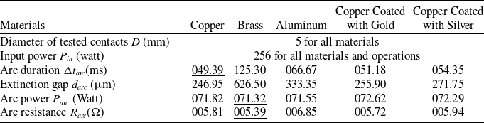
From Fig. 5, the arc duration is equal to 49.39 ms for the opening operation number 5; with this value
 $\Delta t$
can determine the extinction gap (d
arc
). Notice that this duration depends on the materials and shape of the contacts, and it varies from 49 to 130 ms. More details are given in Table II.
The results of arc parameters for different materials contact samples used (operation number 5)

Arc voltage V arc and arc current I arc for contact opening operation number 5 (D ∼5 mm, P in = 256 watts).

As mentioned earlier, the electrical arc can take different forms, lengths and paths (trajectories) when it is ignited; Fig. 6 is a demonstrative synoptic that shows the different cases the arc could take during the gap evolution. In case (a), the electrical arc length (l arc ) and the extinction gap (d arc ) can be equal if the arc is formed between the ends of the contacts.
Dimensional arc parameters (l arc, d arc and d).

Examples of the observed arcing phenomena during tests with (D∼5 mm, P in=256 watst/DC32V).

The length of the arc changes with the increase of the opening operation number. In case (b) the arc is deformed because it followed the least resistant path.
The movable cathode contact will stop when it is completely open. This (d) distance is controlled by machine mechanism, which ensures the opening-closing of this contact. The final inter-electrode distance (d) is always greater than the extinction gap (d arc = 5 mm).
To track the arcing phenomenon generated by the opening of contacts during tests, a special high-speed camera (Sony V RX100) was used in the ITM-CDS laboratory. The following figure illustrates the arcing observations obtained during the tests for the various contacts materials. Those with low copper content are illustrated by photo in Fig. 7a, showing that the luminosity generated by the arc is quite remarkable. With a lesser intensity, the phenomenon is also observed during tests on aluminum contacts given by photo Fig. 7c. Moreover, more significantly is the luminosity released during tests on brass contacts, as shown by photo on Fig. 7b.
From the results collected experimentally, our approach to comparing different materials involves the identification of the relevant indicators (parameters) required to decide on contacts quality. The focus here will be on contact diameter, arc duration, arc extinction gap, power and energy. The following is a description of the formulations required to obtain these parameters.
As a preliminary deduction, we can link this intensity magnitude evolution inversely to the energy flowed by the different materials contacts illustrated in Table III, where aluminum contacts have the lowest energy average at 2.53 Joules, and brass has the highest at 10.15 Joules.
Arc power for different materials used (operation number 5, contact diameter D∼5 mm, P in= 256 watts).

Arc current and arc voltage during contacts opening (operation number 5, P in= 256 watts).

The arc extinction gap ‘d arc ’ can be calculated by Equation (1).
 \begin{align}{d_{arc}} = {v_{open}}.\Delta t\end{align}
In this work, the opening velocity “vopen ” equal to 5 mm/s and the final value distance between the electrodes ‘d ’ set to 5 mm.
From data test as illustrated in Fig. 5, the obtained arc duration ‘
 $\Delta t$
’ is 49.39 ms, with extinction gap calculated is 246.95 µm. We notice that the value of the arc duration is much inferior to the specified opening gap ‘d’ for the machine. With the same method, we will proceed to the determination of the arc duration for the other contacts material.
The electrical arc power
 ${P_{arc}}(t)$
will be calculated by the following formula (2), the I
arc
and V
arc
values are deduced from the curves in Fig. 5.
 \begin{align}{P_{arc}}(t) = {V_{arc}}(t).{I_{arc}}(t)\end{align}
The electrical arc energy
 ${E_{arc}}(t)$
is calculated by:
 \begin{align}{E_{arc}}(t) = \int {{P_{arc}}} (t)dt = \int {[{V_{arc}}(t).} {I_{arc}}(t)].dt = {P_{arc}}.\Delta t\end{align}
From Fig. 5, we can calculate the electric arc resistance
 ${R_{arc}}$
for one opening contact operation:
 \begin{align}{R_{arc}}(t) = \frac{{{V_{arc}}(t)}}{{{I_{arc}}(t)}}\end{align}
Figure 8 shows a typical waveform of the arc power calculated by Equation (2). The curves are plotted for the different materials tested (pure and coated). For this illustration, we have chosen to highlight operation number 5 on contacts with diameter D∼5 mm and an input power of Pin = 256 watt ender a DC voltage of 32 V.
Arc energy of the different materials for 256 watts input power, diameter of the samples D∼5 mm.

From Fig. 8, we notice that the arc duration ‘
 $\Delta t$
’ vary with materials change. The copper curve in brown colour presented (arc power) calculated by the Equation (2) and it corresponds to the arc current and arc voltage
 $(I_{arc}, V_{arc})$
of the fifth operation illustrated in Fig. 5.
Figure 9 describes the evolution of the arc characteristics during the contacts opening; it is the arc voltage V arc as a function of the current flowing through the arc I arc . The voltage drops abruptly while the current increases rapidly for materials tested (copper, gold-coated copper and silver-coated copper). The electric field is not constant between the inter-electrode gap.
From Fig. 9 and Equation 4, we can deduce or calculate the arc resistance for all tested materials in this study while considering that the arc voltage varies linearly with the arc current giving a constant resistance ‘
 ${R_{arc}}$
’ for all materials.
As previously mentioned, the summarised results of the material comparison are dressed in Table II, based on the arc parameters measured during opening operation number 5. The parameters considered for comparison are: the arc parameters are, arc duration, extinction gap, arc power and arc resistance; The input power Pin is 256 Watt under voltage DC of 32 V.
Figure 10 illustrates the arc energy plots deduced by Equation (3) over a number of successive contact opening/closing operations. For this presentation we limited analysis to 300 operations out of more than 1,700 (see Table III), always under the same conditions with the same configuration (see Fig. 4), i.e. contact sample diameter D ∼5 mm and input power Pin= 256 watts at 32 V DC.
From the curves E arc of energy drawn in Fig. 10, it is clear that pure copper contacts and those coated with gold and silver show a similar energy level, of around 4 Joules. The random shifting of the peaks is not indicative of any reproducible phenomenon, as it is caused by the random evolution of the surface state of the contacts and the non-repetitive movements with precision during the mechanical moving of the electrodes towards and away from each other.
For brass contacts, the behaviour is distinct from that of copper contacts (pure and coated); after only ten operations, the brass contact completely stops being conductive and doesn’t drain any current, resulting in no arcing after the tenth operation. This phenomenon is due to the formation of an oxide layer on the electrode contact surfaces, blocking the passage of current. Over 300 operations, the behaviour of aluminum electrodes is similar to that of copper electrodes, but with a lower decreasing energy level starting at 3 Joules and approaching zero. This evolution in aluminum electrodes is essentially due to the deformation of the surface under the increase of temperature provoked by the arcing, reconstituting new contact surfaces, and consequently an undesirable deformation of the contacts.
Table III presents a summary comparison between different electrical arc results obtained for different contact sample materials. As a reminder the contacts diameters is 5 mm, the applied input power is 256 watts at DC 32 V. The results presented are the averages of
 $\Delta t$
, P
arc
, E
arc
and number of electrodes opening operations till stops being conductive (end lifetime of the electrodes).
Arc results at the end lifetime for different contact samples materials

The following are some important notices that were drawn from the Table III:
-
• For all the contacts tested, the arcing parameters illustrated in Table III are clearly informative, due to the high-power input. When the contact opens, the current flows through the reduced channels cross-section, leading to an increase in current density. As a result, the contact surfaces overheat due to the Joule effect, melting the points in contact, followed by an explosion of the molten metal bridge. The metal vapors resulting from this explosion facilitate the occurrence of the electric discharge (arc phenomenon).
-
• High arc energy with long arc duration leads to greater degradation of contact surfaces through oxidation and erosion, whatever the nature of the contact sample material, and even to contact deformation (in the case of aluminum). This is because the power of the arc depends on the electrical resistivity of the material and the current density [Reference Kharin and Sarsengeldin38]. It has also been observed between the columns of ‘number of the opening operations’ and the arc energy (Earc) that contact life decreases with increasing arc energy.
-
• Aluminum shows a lower arc length and lower arc duration (022.76 ms) under an input power of 256 watts DC, despite these results the contact lifetime remains averagely low. The causes of the phenomenon are the chemical reaction of aluminum with the ambient environment and the insulating oxide film (Al2O3) deposited on the contact surfaces due to the high arc energy and high arc temperature. The aluminum has a low melting temperature, causing surface deformation. Therefore, using this material is not recommended in similar conditions. In some applications, a conductive grease layer is applied on the contact surfaces [Reference Jackson39, Reference Braunovic40].
-
• The coated materials have given an additional service lifetime to the contact samples, where a significant (1,642 Ops) service lifetime is obtained compared with pure standard materials. The use cycle registered a minimum increase of 24% for gold. The high resistance to corrosion and oxidation makes them excellent solutions in aggressive environments (e.g. under an electrical arc). Thus, with their performance, they give it high service in applications requiring high reliability.
-
• Silver-coated copper is the most efficient material, giving the highest number of operating cycles (1,783 Ops) compared to other materials tested at a high-power input of 256 watts. Equivalent increase to 30% in lifetime compared with pure copper. The electrical and thermal characteristics allow silver to be used in high-current applications. Silver has the highest electrical conductivity of all the metals tested; it can withstand high currents with a voltage drop and a minimum heat release.
3.2 Physical and surface analysis of contacts
After a visual and dimensional inspection of the contacts tested, it was observed that a dark layer had formed on the contacts, preventing direct contact between the electrodes, causing interruption of the current flow and consequently limiting the number of operations in accordance with the electrode properties (see Table III). A preliminary analysis revealed an oxidation film caused by overheating resulting from energy transmitted by the electric arc (see Fig. 11). For further understanding and expertise, a campaign of inspection and spectroscopic analysis was performed on all the contacts tested, using the resources available at the electron microscope and materials science laboratory (LMESM) of the USTO.MB Oran University.
An example of a dark layer, which was deposited on the gold contacts during contact opening/closing operations.

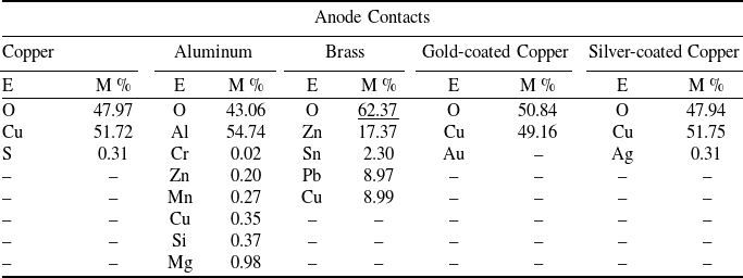
It should be highlighted that the analyses were carried out on electrodes at the end of their service lifetime (when they stopped being conductors), using a scanning electron microscope ‘SEM JOL JSM 6610LA’ [41], a typical microscopic image of the contacts is given in Fig. 12. The results obtained confirmed the oxidation of the contact surfaces as a result of the increase in oxygen levels in the area impacted by the electric arc (see Table IV). In fact, the high energy transmitted by the arc and the high temperature accelerated the rate of oxidation differently according to the materials involved. Contact surfaces become insulating, and the electric current no longer flows.
A chemical composition of anode contacts surface of all materials tested

SEM image of aluminium contact anode (a) and (b) (Input power P in=256 W).

Table IV lists the mass percentages of materials (Cu, Ag, Au, …) and oxide present on the contact surfaces damaged by the arcing process. The oxygen rate measured in the anode contact surface is around 43.06% for the aluminum contact, after just 500 operations; its surface is totally oxidised and becomes completely electrically insulating. An oxygen percentage between 47% and 50% was measured for the other anodes, except for brass, which presented a significantly higher value of 62.37% after only 10 operations. The additional percentages of Zn, Sn and Pb observed for the brass anode are linked to the industrial chemical composition of the brass used, which is CuZn37 [42, 43], an alloy of reinforced copper in solid solution containing 37% zinc and with lower percentages of Sn and Pb. It should be pointed out that mechanical resistance improves when using a brass anode, but conductivity and ductility are reduced compared to pure copper, which explains the highly remarkable discrepancy in the number of operations reported in Table III (10 operations for brass << 1249 operations for the Cu anode).
To decrease the oxidation phenomena in the contact’s surface and increase conductivity, a frequently used alternative is to treat the surface with a more conductive material; in our case, we used a silver and a gold coating. As expected, for surface-treated anodes, there is an increase in the number of operations (1783 operations for silver-coated contacts and 1642 for gold-coated contacts) compared to the pure copper contact. It can be explained by the oxidation process being slowed down in the case of coated contacts.
According to the electrical and thermal properties listed in Table I. Silver is a better thermal (419 W/mK) and electrical (630.102 Ω -1.mm-1) conductor than pure copper (595.102 Ω-1.mm-1, 394 W/mK) or gold-coated contacts (457.102 Ω-1.mm-1, 297 W/mK); this may explain the improvement in performance achieved by this coating.
For the disappearance of gold (0%) and the decrease in silver (0.31%) on the surfaces of coated contacts is strongly linked to the thermal conductivity that caused arcing leading to fusion peaks, then evaporation of these materials.
If we list the electrical resistivity according to Table I, from lowest to highest, we can see that copper has the lowest resistivity at 16.8 × 10⁻⁹, followed by silver-coated contacts, gold, aluminum contacts and finally the highest, which is brass. These resistivity levels could explain the high arc duration for brass (115.10 ms) and the higher luminosity due to the higher energy level (10.15 Joules), causing accelerated oxidation on the contact surface and blocking current flow at 10 operations. Conversely, the low arcing duration obtained for aluminum is 22.76 ms and consequently low energy level are also observed (2.53 Joules).
The limitation of the number of operations in aluminum contacts (lower than copper and coated copper contacts) despite low resistivity, arc duration and energy elapsed can be explained by the fact that the higher power of 111.73 watts (see Table III) causes more intense fusion points, and combined with its deformation capability perceived by its Young’s modulus of 74 Gpa (see Table I) generates a large oxidation surface (see Fig. 12), which rapidly causes this blockage after only 500 operations.
In order to carry out a dimensional inspection of the impact of the arcing phenomenon, images were captured of the contact surfaces. Figure 13 shows the state of the contact surfaces affected by the arcing. These images were taken on fixed anode contacts after several operations that led to the end of the lifetime. The oxidation is clearly apparent at the tip of the contacts, representing a spot; the size and colour are different according to the type of contact. In these spots, crystallised regions are observed, surrounded by black patches of oxide (see the zoom in Fig. 13(a)).
Erosion and oxidation of the contact surfaces by electrical arc (D ∼5 mm, Pin = 256 watts).

In the images in Fig. 13, it can be clearly seen that the size of the area affected by arcing is similar for pure copper, gold-coated and silver-coated contacts; this is due to the convergent electrical characteristics of these materials as described in the previous paragraphs (thermal electrical conductivity, arc energy stability, arc duration stability and arc shape during opening operations).
4.0 Conclusion
In this work, we have investigated the characteristics that influence arcing during the repetitive disconnection phase under power (hot switching), focusing on the electrode materials involved and their tendency to spark. To better understand the arcing phenomenon (responsible for numerous disconnection failures), it was essential to identify and analyse the parameters that trigger or exacerbate this damage.
To validate the findings, key arcing parameters such as applied voltage, current, channel resistance, arc power and arc energy were experimentally measured using a custom-designed test bench developed in the ITM/CDS laboratory. One of the main conclusions drawn from this study is that coated electrodes, particularly those with noble metal coatings, provide more reliable performance and longer lifespan compared to pure metal electrodes. Specifically, surface coatings with gold or silver significantly improved contact durability.
Experimental tests revealed a general trend in power electronics: increasing the input power at the contact level leads to longer and more intense electrical arcs. This also accelerates material transfers through anodic or cathodic erosion. Aluminum, despite showing acceptable arc parameter at a high input power of 256 watts DC, demonstrated a relatively short contact lifespan. This limitation is likely due to rapid deformation after repeated operations and the formation of an insulating oxide layer Al2O3, which results from the material’s low melting point compared to pure or coated copper. For this reason, aluminum is not recommended for aerospace applications under similar conditions. In some cases, a conductive grease film may be applied to improve reliability. Gold-coated copper contacts exhibited favourable arc characteristics and are commonly used in satellite harness connectors, where vibrations are primarily limited to the launch phase. However, their lifespan was lower compared to silver-coated copper, especially in systems subjected to frequent mechanical vibrations such as aircraft, UAVs and drones. Moreover, gold coatings are generally not recommended for high-power contact applications. Brass showed poor performance, with a very low number of successful operations, indicating a high risk of failure. As a result, this material will be excluded from future studies.
Among all materials tested, silver-coated copper demonstrated the best resistance to arcing at high electrical power (256 watts DC), achieving the longest contact lifetime. These promising results support its potential use in next-generation space applications, particularly in reusable electrical power systems. Future work will focus on exploring this material for such missions.