1. Introduction
The rapid development of robot technology has greatly affected people’s work and life in recent years. As a key technology, it has led to a new scientific and technological revolution. Because wheeled–legged robots not only have good adaptability and passing ability over complex terrain but also have the ability to travel at stable and high speeds, they have become a popular research topic.
To allow robots to move in complex, unstructured environments, Zhu et al. [Reference Zhu, Li, Li and Zhai1] combined the advantages of legged and wheeled mobile mechanisms and designed an efficient and steady wheeled–legged stair-climbing mobile robot. To improve the ride performances of mobile robots, Shang et al. [Reference Shang, Qiu, Li and Cheng2] designed a hybrid mobile system with a rocker bogie mechanism and a speed differential balance mechanism suitable for field exploration. Zhang et al. [Reference Zhang, Fei, Lou and Wang3] designed a new wheeled–legged ground mobile robot based on the motion characteristics of a parallelogram link mechanism by combining a swing arm and a planetary gear mechanism. Ma et al. [Reference Ma, Guo and Gao4] proposed a series–parallel hybrid wheeled–legged robot that could adapt to complex terrain and designed an isotropic hexapod-legged mobile robot. Wang et al. [Reference Wang, Tang and Dai5] applied a parallelogram mechanism to a wheeled–legged design and proposed a new linkage-jointed wheeled–legged robot design. Reconfiguration between wheel driving and leg walking for this mechanism was local and slow. Before and after reconfiguration, the structure, shape, and position of the center of mass did not change much, and the reconfiguration inertia was small. Grandet al. [Reference Grand, Benamar, Fédéric and Bidaud6] designed a mobile robot with wheels mounted at the end of four legs, which could either walk using the legs or travel using the wheels. Boston Dynamics [Reference Oliver Peiró7] has developed a mobile robot with two leg wheels, named Handle, which can realize fast travel through its leg wheels, but it cannot walk. Neither of the two kinds of mobile robots with leg wheels described above can undergo reconfiguration between wheeled driving and leg walking.
The wheeled–legged metamorphic robot studied in this paper is a new type of robot. The robot combines a traditional electric vehicle with a biped robot through a lifting mechanism and folding legs, and thus, it has two reconfigurable modes: car mode and humanoid mode. When the metamorphic robot is in car mode, its frame is not a unified unit but has a front part and a rear part, and they can be connected and separated from each other. Unlike the leg structure of a traditional biped robot, the legs of the metamorphic robot not only can be extended to realize a walking function when in humanoid mode but can also be folded below the chassis when in car mode. Because the shape of the metamorphic robot changes greatly and the position of the center of mass changes significantly before and after the reconfiguration, tipping and instability can easily occur during reconfiguration. In order to improve the stability of the reconfiguration process, a cross-shaped device was designed and installed on the upper part of the frame of the metamorphic robot to adjust the position of the center of mass (that is, changing the zero-moment point (ZMP) position of the system). This device can also control the stability of the robot when it is walking in humanoid mode. The metamorphic robot was designed by adding a leg structure to the traditional car structure, so that the robot has a walking function that enables it to cross a variety of complex roads by adjusting its center of mass. At the same time, it retains the characteristics of a traditional car and can drive at high speed on flat roads. Therefore the metamorphic robot can be widely used in military and civilian fields, such as for earthquake relief, interstellar exploration, and battlefield reconnaissance.
As a new type of mechanism proposed by Dai [ Reference Dai and Zhang8,Reference Dai and Jones9], a metamorphic mechanism features variable functions and variable-topology structure in multiple working stages [Reference Wang and Dai10]. Numerous studies have been carried out on metamorphic mechanisms worldwide. For example, Dai and Jones [Reference Dai and Rees Jones11] described the configuration of the metamorphic mechanism using a topological graph and proposed a configuration transformation matrix. Yan and Kuo [Reference Yan and Kuo12] proposed a variable topological kinematic pair as well as changes in the topological graph, and they qualitatively analyzed the variable topological configuration. Zhang et al. [ Reference Zhang, Wang and Dai13,Reference Yuchen, Ganwei and Hongzhou14] established a model of a metamorphic mechanism based on genetic theory. The research described above focused mostly on structural aspects, and there have been few studies on the motion analysis of each configuration, especially the reconstruction of the motion between the configurations.
Metamorphic robots can be widely used to conduct military reconnaissance and combat missions in battlefield environments. Due to the rapidly changing battlefield environments and the need to traverse narrow passages, robot morphing is required to have rapid global reconfiguration characteristics. A rapid reconfiguration involves high speeds and large inertia, but it must not cause impact damage to the on-board precision instruments. Therefore, reconfiguration movement must be quick and smooth. Furthermore, global reconfiguration causes the shape and the position of the center of mass to change significantly before and after morphing, causing the robot’s support area to change, especially in the process of coupled reconfiguration (i.e., the lifting and leg mechanisms are reconfigured and morph at the same time) from support mode (the intermediate state between the car state and the humanoid state, that is, the state when the leg structure of the metamorphic robot extends to just touch the ground) to humanoid mode. During the motion coupling process, as the support area becomes smaller, instability is prone to occur during the system reconfiguration. Due to the characteristics and motion requirements of the rapid global reconfiguration described above, it is necessary to study the reconfiguration motion between support mode and humanoid mode of the metamorphic robot to satisfy the smoothness and stability requirements of the reconfiguration motion.
In this study, a metamorphic robot structure that can switch between wheels and legs was designed. Based on Lie algebra, Lie group theory, and the screw theory [Reference Murray, Li and Sastry15–Reference Liu, Qu, Xu, Zou, Song, Tang, Ma and Jiang20], a kinematics model for the reconfiguration process of the metamorphic robot and a level lifting model based on the requirement that the front and rear frames should be held level in the reconfiguration were established. Based on the reconfiguration time, the angle of the supporting joints, and the angle of the humanoid joint, rules for the rotation of each joint in the reconfiguration process were designed to ensure the smoothness of the reconfiguration movement. Based on the kinematics model of the reconfiguration and the rules of motion of the rotating joints, the ZMP [Reference Vukobratovic and Borovac21–Reference Farizeh and Sadigh25] model of the entire robot in the reconfiguration process was established. To meet the stability requirements of the reconfiguration, the design of the landing positions of the support feet was optimized by combining the ZMP model and the inverse kinematics of the support foot landing. Finally, the motion smoothness and stability during the reconfiguration were verified by prototype tests.
2. Structure and reconfiguration planning of metamorphic robots
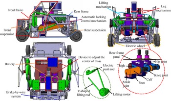
The proposed metamorphic robot is a wheeled–legged hybrid ground mobile robot. Figure 1 shows the overall structural design of the robot. It can drive fast on its wheels in car mode and walk in humanoid mode. This robot is able to maintain stability during the reconfiguration process, and it can operate without its components interfering with each other.
Three-dimensional model structure of the metamorphic robot.

As shown in Fig. 1, when the metamorphic robot is in car mode, the front and rear bodies are connected and fixed as a unit through an automatic locking control mechanism. The wheels in the front and rear bodies are electric wheels integrated with in-wheel motors. The four electric wheels can drive the car, and steering can be realized by the differential speed between the electric wheels. Braking and deceleration are accomplished by a brake-by-wire system. The McPherson suspension with a relatively simple structure is used for the front and rear suspensions to make the structure compact and reduce the impact caused by uneven pavement during driving. The lifting mechanism is composed of a lifting rod and an electric push rod on both sides. The lifting rod on one side is V-shaped, and its rear part is connected to the rear frame. The upper lifting rod of the V-shaped lifting rod is connected to the pushing end of the electric push rods. The lower lifting rod and the end of the electric push rod are connected to the front frame. The lifting rod on the other side is used as a supporting rod and is placed in parallel with the lower lifting rod of the V-shaped lifting rod. The lifting rod connects to the front and rear frames at each end. The lifting mechanism uses electric push rods and lifting motors as the power source, which can achieve level lifting of the front frame of the robot during the reconfiguration process. A cross-shaped device for adjusting the center of mass was designed to maintain the stability of the robot during the reconfiguration process or during humanoid walking. The device uses the battery as a center-of-mass adjusting slider, allowing it to change the position of the center of mass of the entire robot longitudinally and laterally.
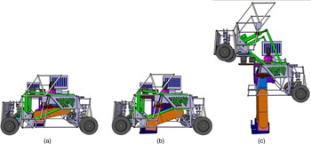
When the metamorphic robot is moving in car mode, the automatic locking control mechanism locks the front and rear frames as a unit, and at this time, the leg mechanism is folded and stowed in the lower part of the vehicle chassis to avoid contact with the ground, and the motor is in the locked state because the power supply to the motor mounted on the leg has been cut off. When reconfiguration is required, the joint motor of the folding legs is unlocked, and the leg mechanism is expanded until the feet touches the ground. The stability of the subsequent reconfiguration is improved by expanding the support area, and this state is called support mode. Then, the front and rear bodies are unlocked and separated through the automatic locking control mechanism. Under the action of the lifting mechanism, the front frame is lifted to become the upper body of the robot, and the leg mechanism is further expanded until the humanoid is standing. At this time, the reconfiguration is completed, and this state is called humanoid mode. The three configurations of the metamorphic robot during the reconfiguration process are shown in Fig. 2.
Configuration modes of the metamorphic robot: (a) car mode, (b) support mode, and (c) humanoid mode.

3. Kinematic analysis of reconfiguration
The leg mechanisms on both sides of the metamorphic robot have the same structural design and are placed symmetrically. Therefore, the leg mechanisms on both sides of the metamorphic robot are analyzed as a whole. During the reconfiguration process, the robot can be considered to move on the sagittal plane, and the leg mechanism can be simplified as the RRR (R denotes a revolute joint) series chain mechanism, and the lifting mechanism can be simplified into a two degree-of-freedom RRRPR (P denotes a prismatic joint) planar parallel chain mechanism. The left leg mechanism and the lifting mechanism are in different planes. The three rotation axes of the hip joint are orthogonal to each other and intersect at one point. The two rotation axes of the ankle joint are perpendicular to each other. The knee axis, the hip flexion and extension axes, and the ankle joint flexion and extension axes are parallel, and this configuration meets the Pieper criterion for the existence of a closed-form solution for the leg mechanism [Reference Yu, Wang, Wang, Gu and Wang26]. During the reconfiguration process, these axes are also parallel to the axis of the lifting joint, the rotation axis of lower part of the V-shaped lifting rod and the front frame, and the rotation axis of the electric push rod base and the front frame.
3.1. Forward kinematics modeling
In the study of the kinematics of complex spatial mechanisms, screw theory has the advantages of a clear modeling structure and it avoids computational singularities. It has extensive and expansive applications in the field of advanced spatial mechanisms. Screw theory was used to establish a kinematics model of the parking reconfiguration of the metamorphic robot.
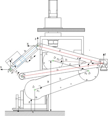
The support mode of the robot, as shown in Fig. 2(b), is taken as the reference posture. The base coordinate system S is established with the center of the closed convex polygon formed by the contacts between a support foot and the ground as the origin. The X-axis points in the movement direction of the robot. The Y-axis points to the left of the movement direction of the robot, i.e., perpendicular to the paper and pointing outward. The Z-axis points vertically upward. The front frame is the end mechanism of the system.
The tool coordinate system T is established at the hinge point of the front frame and the base of the electric push rod. The directions of the axes of T and S coincide. A schematic diagram of the joint motions of the metamorphic robot is shown in Fig. 3. The parameters are shown in Table I.
Schematic diagram of the joint motions of the metamorphic robot.

Structural parameters of the metamorphic robot.

In the support mode of the robot, the center of mass of the end mechanism of the system (that is, the front frame) is at the coordinates
 $(x_{5}^{0},y_{5}^{0},z_{5}^{0})$
in S, and its initial configuration matrix is as follows:
 \begin{align}\begin{array}{c} g_{ST}\left(0\right)=\left[\begin{array}{c@{\quad}c} \begin{array}{c@{\quad}c} 1 & 0\\[5pt] 0 & 1 \end{array} & \begin{array}{c@{\quad}c} 0 & x_{5}^{0}\\[5pt] 0 & y_{5}^{0} \end{array}\\[5pt] \begin{array}{c@{\quad}c} 0 & 0\\[5pt] 0 & 0 \end{array} & \begin{array}{c@{\quad}c} 1 & z_{5}^{0}\\[5pt] 0 & 1 \end{array} \end{array}\right]\in SE\left(3\right), \end{array}\end{align}
where SE (3) represents the special Euclidean group in the Lie group, which describes the three-dimensional configuration space of a rigid body.
According to the structural analysis, joints 1–5 are all rotating joints, and the unit vector axis,
 $\omega _{i}$
(i = 1–5), is defined as follows:
 \begin{align} \begin{array}{c} \omega _{i}=\left[\omega _{x}\; \omega _{y}\; \omega _{z}\right]^{T}=\left[\begin{array}{c@{\quad}c@{\quad}c} 0 & -1 & 0 \end{array}\right]^{T}. \end{array}\end{align}
The skew-symmetric matrix,
 $\hat{\omega }_{i}$
(i = 1–5), is expressed as follows:
 \begin{align} \begin{array}{c} \hat{\omega }_{i}=\left[\begin{array}{c@{\quad}c@{\quad}c} 0 & -\omega _{z} & \omega _{y}\\[5pt] \omega _{z} & 0 & -\omega _{x}\\[5pt] -\omega _{y} & \omega _{x} & 0 \end{array}\right]=\left[\begin{array}{c@{\quad}c@{\quad}c} 0 & 0 & -1\\[5pt] 0 & 0 & 0\\[5pt] 1 & 0 & 0 \end{array}\right]\in so(3), \end{array}\end{align}
where so (3) represents the vector space of all third-order skew-symmetric matrices.
When the ith rod rotates by an angle
 $\theta _{i}$
at a constant speed about the unit vector axis of
 $\hat{\omega }_{i}$
, the following is obtained:
 \begin{align} \begin{array}{c} R(\omega _{i},\theta _{i})=e^{{\hat{\omega }_{i}}{\theta _{i}}}\,=\left[\begin{array}{c@{\quad}c@{\quad}c} \cos \theta _{i} & 0 & -\sin \theta _{i}\\[5pt] 0 & 1 & 0\\[5pt] \sin \theta _{i} & 0 & \cos \theta _{i} \end{array}\right]\in SO(3), \end{array}\end{align}
where
 $R(\omega _{i},\theta _{i})$
represents the posture matrix of the ith rod, SO (3) represents the special orthogonal group in the Lie group, also known as the three-dimensional rotation group, and
 $\theta _{i}$
is a variable angle of the joint and is positive for the clockwise rotation around the Y-axis.
For an arbitrary point
 $p_{i}$
on the axis of a joint, the following is obtained:
 \begin{align} \begin{array}{c} \begin{array}{c} p_{1}=\left[\begin{array}{c} l_{1x}\\[5pt] 0\\[5pt] l_{1z} \end{array}\right], p_{2}=\left[\begin{array}{c} l_{2x}\\[5pt] 0\\[5pt] l_{2z} \end{array}\right], p_{3}=\left[\begin{array}{c} l_{3x}\\[5pt] 0\\[5pt] l_{3z} \end{array}\right],\\[5pt] p_{4}=\left[\begin{array}{c} l_{4x}\\[5pt] 0\\[5pt] l_{4z} \end{array}\right], p_{5}=\left[\begin{array}{c} l_{5x}\\[5pt] 0\\[5pt] l_{5z} \end{array}\right].\, \end{array} \end{array}\end{align}
The coordinates of each motion screw,
 $\xi _{i}=\left[\begin{array}{c} v_{i}\\ \omega _{i} \end{array}\right]=\left[\begin{array}{c} -\omega _{i}\times p_{i}\\\omega _{i} \end{array}\right]$
(i = 1–5) can be expressed as follows:
 \begin{align} \begin{array}{c} \begin{array}{c} \xi _{1}=\left[\begin{array}{c} \begin{array}{c} l_{1z}\\[5pt] 0\\[5pt] -l_{1x} \end{array}\\[5pt] \begin{array}{c} 0\\[5pt] -1\\[5pt] 0 \end{array} \end{array}\right];\; \xi _{2}=\left[\begin{array}{c} \begin{array}{c} l_{2z}\\[5pt] 0\\[5pt] -l_{2x} \end{array}\\[5pt] -\begin{array}{c} 0\\[5pt] 1\\[5pt] 0 \end{array} \end{array}\right];\; \xi _{3}=\left[\begin{array}{c} \begin{array}{c} l_{3z}\\[5pt] 0\\[5pt] -l_{3x} \end{array}\\[5pt] -\begin{array}{c} 0\\[5pt] 1\\[5pt] 0 \end{array} \end{array}\right];\\[5pt] \xi _{4}=\left[\begin{array}{c} \begin{array}{c} l_{4z}\\[5pt] 0\\[5pt] -l_{4x} \end{array}\\[5pt] -\begin{array}{c} 0\\[5pt] 1\\[5pt] 0 \end{array} \end{array}\right];\; \xi _{5}=\left[\begin{array}{c} \begin{array}{c} l_{5z}\\[5pt] 0\\[5pt] -l_{5x} \end{array}\\[5pt] -\begin{array}{c} 0\\[5pt] 1\\[5pt] 0 \end{array} \end{array}\right]. \end{array} \end{array}\end{align}
Similarly, introducing the motion screw
 $\hat{\xi }_{i}=\left[\begin{array}{c@{\quad}c} \hat{\omega }_{i} & v_{i}\\ 0 & 0 \end{array}\right]_{4\times 4}\in se(3)$
, the
 $\hat{\xi }_{i}\theta _{i}$
matrix in the exponential form is as follows:
 \begin{align} \begin{array}{c} e^{{\hat{\xi }_{i}}{\theta _{i}}}=\begin{cases} \left[\begin{array}{c@{\quad}c} e^{{\hat{\omega }_{i}}{\theta _{i}}} & \left(I-e^{{\hat{\omega }_{i}}{\theta _{i}}}\right)\left(\omega _{i}\times v_{i}\right)+\omega _{i}{\omega _{i}}^{T}v_{i}\theta _{i}\\[5pt] 0 & 1 \end{array}\right]\\[5pt] \left(\omega _{i}\neq 0\right)\\[5pt] \,\left[\begin{array}{c@{\quad}c} I & v_{i}\theta _{i}\\[5pt] 0 & 1 \end{array}\right]\left(\omega _{i}=0\right)\,\, \end{cases}. \end{array}\end{align}
According to (7),
 $e^{{\hat{\xi }_{i}}{\theta _{i}}}$
(i = 1–5) can be calculated as follows:
 \begin{align} \begin{array}{c} e^{\widehat{\xi _{i}}{\theta _{i}}}=\left[\begin{array}{c@{\quad}c} \begin{array}{c@{\quad}c} \cos \theta _{i} & 0\\[5pt] 0 & 1 \end{array} & \begin{array}{c@{\quad}c} -\sin \theta _{i} & p_{ix}\\[5pt] 0 & 0 \end{array}\\[5pt] \begin{array}{c@{\quad}c} \sin \theta _{i} & 0\\[5pt] 0 & 0 \end{array} & \begin{array}{c@{\quad}c} \cos \theta _{i} & p_{iz}\\[5pt] 0 & 1 \end{array} \end{array}\right], \end{array}\end{align}
where
 \begin{equation*} \begin{array}{c} p_{ix}=\,l_{iz}\sin \theta _{i}-l_{ix}\left(\cos \theta _{i}-1\right),\\[5pt] p_{iz}=-l_{ix}\sin \theta _{i}-l_{iz}\left(\cos \theta _{i}-1\right). \end{array} \end{equation*}
The combination of the movements of all the joints yields the kinematics model of the end mechanism (i.e., the front frame of the robot) of the metamorphic robot system:
 \begin{align} g_{ST}(\theta )=e^{{\hat{\xi }_{1}}{\theta _{1}}}e^{{\hat{\xi }_{2}}{\theta _{2}}}e^{{\hat{\xi }_{3}}{\theta _{3}}}e^{{\hat{\xi }_{4}}{\theta _{4}}}e^{{\hat{\xi }_{5}}{\theta _{5}}}g_{ST}(0). \end{align}
Equations (1)–(8) are combined, and we define
 $c_{i}=\cos \theta _{i}$
,
 $s_{i}=\sin \theta _{i}$
,
 $c_{ij\ldots n}=\cos (\theta _{i}+\theta _{j}+\ldots +\theta _{n}),$
and
 $s_{ij\ldots n}=\sin (\theta _{i}+\theta _{j}+\ldots +\theta _{n})$
.
Equation (9) can be written as follows:
 \begin{align} \begin{array}{c} \begin{array}{c} g_{ST}\left(\theta \right)=e^{{\hat{\xi }_{1}}{\theta _{1}}}e^{{\hat{\xi }_{2}}{\theta _{2}}}e^{{\hat{\xi }_{3}}{\theta _{3}}}e^{{\hat{\xi }_{4}}{\theta _{4}}}e^{{\hat{\xi }_{5}}{\theta _{5}}}g_{ST}\left(0\right)\\[5pt] =\left[\begin{array}{c@{\quad}c} \begin{array}{c@{\quad}c} c_{12345} & 0\\[5pt] 0 & 1 \end{array} & \begin{array}{c@{\quad}c} -s_{12345} & p_{x}\\[5pt] 0 & y_{5}^{0} \end{array}\\[5pt] \begin{array}{c@{\quad}c} s_{12345} & 0\\[5pt] 0 & 0 \end{array} & \begin{array}{c@{\quad}c} c_{12345} & p_{z}\\[5pt] 0 & 1 \end{array} \end{array}\right]\, \end{array}, \end{array}\end{align}
where
 \begin{align*} p_{x}&=\left(x_{5}^{0}-l_{5x}\right)c_{12345}+\left(l_{5z}-z_{5}^{0}\right)s_{12345}+\left(l_{5x}-l_{4x}\right)c_{1234}+\left(-l_{5z}\right)s_{1234}+\left(l_{4x}-l_{3x}\right)c_{123}\\[5pt] & \quad +\left(l_{3z}-l_{4z}\right)s_{123}+\left(l_{3x}-l_{2x}\right)c_{12}+\left(l_{2z}-l_{3z}\right)s_{12}+\left(l_{1z}-l_{2z}\right)s_{1}+l_{2x}c_{1}, \\[5pt] p_{z} & = (z_{5}^{0}-l_{5z})c_{12345}+(x_{5}^{0}-l_{5x})s_{12345}+(l_{5z}-l_{4z})c_{1234}+(l_{5x}-l_{4x})s_{1234}+(l_{4z}-l_{3z})c_{123} \\[5pt] & \quad +(l_{4x}-l_{3x})s_{123}+(l_{3z}-l_{2z})c_{12}+(l_{3x}-l_{2x})s_{12}+(l_{2z}-l_{1z})c_{1}+ l_{2x}s_{1}+l_{1z} \end{align*}
3.2. Level-lifting motion design
The geometric relationships show that if the rear frame remains level during the reconfiguration process, then
 \begin{align} \begin{array}{c} \theta _{1}+\theta _{2}+\theta _{3}=0. \end{array}\end{align}
If the front frame being lifted remains level, then
 \begin{align} \begin{array}{c} \theta _{4}+\theta _{5}=0. \end{array}\end{align}
The following is obtained by substituting (11) and (12) into (10):
 \begin{align} \begin{array}{c} \begin{array}{c} g_{ST}\left(\theta \right)=e^{{\hat{\xi }_{1}}{\theta _{1}}}e^{{\hat{\xi }_{2}}{\theta _{2}}}e^{{\hat{\xi }_{3}}{\theta _{3}}}e^{{\hat{\xi }_{4}}{\theta _{4}}}e^{{\hat{\xi }_{5}}{\theta _{5}}}g_{ST}\left(0\right)\\[5pt] =\left[\begin{array}{c@{\quad}c} \begin{array}{c@{\quad}c} 1 & 0\\[5pt] 0 & 1 \end{array} & \begin{array}{c@{\quad}c} 0 & p_{x}\\[5pt] 0 & y_{5}^{0} \end{array}\\[5pt] \begin{array}{c@{\quad}c} 0 & 0\\[5pt] 0 & 0 \end{array} & \begin{array}{c@{\quad}c} 1 & p_{z}\\[5pt] 0 & 1 \end{array} \end{array}\right], \end{array} \end{array}\end{align}
where
 \begin{align*} p_{x}& =\left(l_{5x}-l_{4x}\right)c_{4}+\left(l_{4z}-l_{5z}\right)s_{4}+\left(l_{3x}-l_{2x}\right)c_{12}+\left(l_{2z}-l_{3z}\right)s_{12}+\left(-l_{2z}\right)s_{1}+l_{2x}c_{1}+\left(x_{5}^{0}-l_{5x}\right)\\[5pt] & \quad +\left(l_{4x}-l_{3x}\right),+\left(x_{5}^{0}-l_{5x}\right)+\left(l_{4x}-l_{3x}\right),\\[5pt] p_{z}&=(l_{5z}-l_{4z})c_{4}+(l_{5x}-l_{4x})s_{4}+(l_{3z}-l_{2z})c_{12}+(l_{3x}-l_{2x})s_{12}+(l_{2z}-l_{1z})c_{1}+l_{2x}s_{1} \\[5pt] & \quad +(z_{5}^{0}-l_{5z})+(l_{4z}-l_{3z})+l_{1z} \end{align*}
In addition, the front frame level-lifting mechanism contains two driving links, the lift motor, and the electric push rod. For the front frame to remain level during lifting, the angle of rotation of the lifting rod about the axis of the lifting joint,
 $\theta _{4}$
, and the stroke of electric push rod,
 $\theta _{7}$
, must satisfy a certain relationship. The analysis indicates that the lifting mechanism can be regarded as a planar closed-chain mechanism composed of the lifting rods, front frame, and electric push rod. The relationship between
 $\theta _{4}$
and
 $\theta _{7}$
can be then solved and analyzed by equating the end postures determined by every branch of the kinematic chain of the closed-chain mechanism [Reference Zhang, Fu and Wang27–Reference Maradkar and Manivannan29]. As shown in Fig. 4, a base coordinate system S
′ is established at the hinge point of the lower part of the V-shaped lifting rod and the rear frame. The tool coordinate system T
′ is established at the hinge point of the V-shaped lifting rod and the electric push rod. The initial state is still the state as shown in Fig. 3. The coordinates of the origin of T
′ in S
′ is
 $(x',0,z')$
, and it follows that
 \begin{align} \begin{array}{c} \begin{array}{c} g_{S'T'}\left(0\right) \end{array}=\left[\begin{array}{c@{\quad}c} \begin{array}{c@{\quad}c} 1 & 0\\[5pt] 0 & 1 \end{array} & \begin{array}{c@{\quad}c} 0 & x'\\[5pt] 0 & 0 \end{array}\\[5pt] \begin{array}{c@{\quad}c} 0 & 0\\[5pt] 0 & 0 \end{array} & \begin{array}{c@{\quad}c} 1 & z'\\[5pt] 0 & 1 \end{array} \end{array}\right], \end{array}\end{align}
Relationship between the rotation angle of the lifting joint and the stroke of the electric push rod.

Similar to joints 4 and 5, joint 6 is a rotating joint. The unit vector of the rotation axis of joint 6 is as follows:
 \begin{align} \begin{array}{c} w_{6}=[0-10]^{T}. \end{array}\end{align}
Similarly, for an arbitrary point on the axis of the screw,
 $p_{6}$
,
 \begin{align} \begin{array}{c} p_{6}=\left[\begin{array}{c@{\quad}c@{\quad}c} l_{6x} & 0 & l_{6z} \end{array}\right]^{T}, \end{array}\end{align}
 \begin{align} \begin{array}{c} \xi _{6}=\left[\begin{array}{c@{\quad}c@{\quad}c} \begin{array}{c@{\quad}c} l_{6z} & 0 \end{array} & \begin{array}{c@{\quad}c} -l_{6x} & 0 \end{array} & \begin{array}{c@{\quad}c} -1 & 0 \end{array} \end{array}\right]^{T}. \end{array}\end{align}
From (7), it follows that
 \begin{align} \begin{array}{c} e^{{\hat{\xi }_{6}}{\theta _{6}}}=\left[\begin{array}{c@{\quad}c} \begin{array}{c@{\quad}c} \cos \theta _{6} & 0\\[5pt] 0 & 1 \end{array} & \begin{array}{c@{\quad}c} -\sin \theta _{6} & p_{6x}\\[5pt] 0 & 0 \end{array}\\[5pt] \begin{array}{c@{\quad}c} \sin \theta _{6} & 0\\[5pt] 0 & 0 \end{array} & \begin{array}{c@{\quad}c} \cos \theta _{6} & p_{6z}\\[5pt] 0 & 1 \end{array} \end{array}\right], \end{array}\end{align}
where
 \begin{align*}p_{6x}&=l_{6\mathrm{z}}\sin \theta _{6}-l_{6x}(\cos \theta _{6}-1),\\[5pt]
p_{6z}&=-l_{6x}\sin \theta _{6}-l_{6z}(\cos \theta _{6}-1).
\end{align*}
Joint 7 is a slip joint. The unit vector of the translation axis of joint 7 is as follows:
 \begin{align} \begin{array}{c} v7=[{\nu _{7x}}\quad 0\quad {\nu _{7z}}]^{T}, \end{array}\end{align}
where
 $v_{7x}$
and
 $v_{7z}$
are the components of the unit linear velocity vector of joint 7 on the X- and Z-axes, respectively, and
 ${v_{7x}}^{2}{+v_{7z}}^{2}=1$
.
The following is also obtained:
 \begin{align} \begin{array}{c} \xi _{7}=\left[\begin{array}{c@{\quad}c} \begin{array}{c@{\quad}c} v_{7x} & 0 \end{array} & \begin{array}{c@{\quad}c@{\quad}c@{\quad}c} v_{7\mathrm{z}} & 0 & 0 & 0 \end{array} \end{array}\right]^{T}. \end{array}\end{align}
Similarly, from (7), it follows that
 \begin{align} \begin{array}{c} e^{{\hat{\xi }_{7}}{\theta _{7}}}=\left[\begin{array}{c@{\quad}c} \begin{array}{c@{\quad}c} 1 & 0\\[5pt] 0 & 1 \end{array} & \begin{array}{c@{\quad}c} 0 & \theta _{7}\nu _{7x}'\\[5pt] 0 & 0 \end{array}\\[5pt] \begin{array}{c@{\quad}c} 0 & 0\\[5pt] 0 & 0 \end{array} & \begin{array}{c@{\quad}c} 1 & \theta _{7}\nu _{7z}\\[5pt] 0 & 1 \end{array} \end{array}\right]. \end{array}\end{align}
Substituting the exponential matrix corresponding to the two branch chains into the exponential product equation yields the structural equation of the level-lifting mechanism:
 \begin{align} \begin{array}{c} g_{S'T'}(\theta )=e^{{\hat{\xi }_{4}}{\theta _{4}}}e^{{\hat{\xi }_{5}}{\theta _{5}}}e^{{\hat{\xi }_{6}}{\theta _{6}}}e^{{\hat{\xi }_{7}}{\theta _{7}}}g_{S'T'}(0)=e^{{\hat{\xi }_{4}}{\theta _{4}}}g_{S'T'}(0). \end{array}\end{align}
Analysis shows that
 \begin{align} \begin{array}{c} (e^{{\hat{\xi }_{4}}{\theta _{4}}})^{-1}g_{S'T'}(\theta )[g_{S'T'}(0)]^{-1}=e^{{\hat{\xi }_{5}}{\theta _{5}}}e^{{\hat{\xi }_{6}}{\theta _{6}}}e^{{\hat{\xi }_{7}}{\theta _{7}}}I. \end{array}\end{align}
where I is the fourth-order unit matrix.
Combining (8), (12), (18), (21), and (23) yields the following:
 \begin{align} \begin{array}{c} \begin{cases} l_{6x}\cos \theta _{4}-l_{6x}+l_{6z}\sin \theta _{4}+\theta _{7}v_{7x}=0\\[5pt] -\,l_{6z}+l_{6z}\cos \theta _{4}-l_{6x}\sin \theta _{4}+\theta _{7}v_{7z}=0 \end{cases}. \end{array}\end{align}
The following is further obtained:
 \begin{align} \begin{array}{c} \begin{cases} \theta _{7}=\sqrt{a^{2}+b^{2}}\\[5pt] a=l_{6x}\cos \theta _{4}-l_{6x}+l_{6z}\sin \theta _{4}\\[5pt] b=-l_{6z}+l_{6z}\cos \theta _{4}-l_{6x}\sin \theta _{4} \end{cases}. \end{array}\end{align}
Using the equations presented above, a simulation model was built using MATLAB/Simulink. The simulation results are shown in Fig. 4. In support mode of the robot, the homogeneous coordinates of the centers of mass of the ankle, calf, thigh, rear frame, lower lifting rod (including support rod), front frame, electric push rod, and upper lifting rod are
 $c_{i}=[x_{i}^{0}y_{i}^{0}z_{i}^{0}1]^{T}$
(i = 1–7). Based on the kinematics model of reconfiguration while parked and the level lifting model, the homogeneous coordinates of the center of the mass of the ith part of the robot,
 $C_{i}$
, in the reconfiguration process, can be obtained as follows:
Ankle:
 \begin{align} \begin{array}{c} C_{0}=[{x_{0}}\quad {y_{0}}\quad {z_{0}}\quad 1]^{T}=c_{0}, \end{array}\end{align}
Calf:
 \begin{align} \begin{array}{c} C_{1}=[{x_{1}}\quad{y_{1}}\quad{z_{1}}\quad 1]^{T}=e^{{\hat{\xi }_{1}}{\theta _{1}}}c_{1}, \end{array}\end{align}
Thigh:
 \begin{align} \begin{array}{c} C_{2}=[{x_{2}}\quad{y_{2}}\quad{z_{2}}\quad 1]^{T}=e^{{\hat{\xi }_{1}}{\theta _{1}}}e^{{\hat{\xi }_{2}}{\theta _{2}}}c_{2}, \end{array}\end{align}
Rear frame:
 \begin{align} \begin{array}{c} C_{3}=\left[x_{3}\quad y_{3}\quad z_{3}\quad 1\right]^{T}=e^{{\hat{\xi }_{1}}{\theta _{1}}}e^{{\hat{\xi }_{2}}{\theta _{2}}}{e^{{\hat{\xi }_{3}}{\theta _{3}}}}c_{3}, \end{array}\end{align}
Lower lifting rod:
 \begin{align} \begin{array}{c} C_{4}=\left[x_{4}\quad y_{4}\quad z_{4}\quad 1\right]^{T}=e^{{\hat{\xi }_{1}}{\theta _{1}}}e^{{\hat{\xi }_{2}}{\theta _{2}}}{e^{{\hat{\xi }_{3}}{\theta _{3}}}}{e^{{\hat{\xi }_{4}}{\theta _{4}}}}c_{4}, \end{array}\end{align}
Front frame:
 \begin{align} \begin{array}{c} C_{5}=\left[x_{6}\quad y_{6}\quad z_{6}\quad 1\right]^{T}=e^{{\hat{\xi }_{1}}{\theta _{1}}}e^{{\hat{\xi }_{2}}{\theta _{2}}}{e^{{\hat{\xi }_{3}}{\theta _{3}}}}{e^{{\hat{\xi }_{4}}{\theta _{4}}}}{e^{{\hat{\xi }_{5}}{\theta _{5}}}}c_{5}, \end{array}\end{align}
Electric push rod:
 \begin{align} \begin{array}{c} C_{6}=\left[x_{6}\quad y_{6}\quad z_{6}\quad 1\right]^{T}=e^{{\hat{\xi }_{1}}{\theta _{1}}}e^{{\hat{\xi }_{2}}{\theta _{2}}}{e^{{\hat{\xi }_{3}}{\theta _{3}}}}{e^{{\hat{\xi }_{4}}{\theta _{4}}}}{e^{{\hat{\xi }_{5}}{\theta _{5}}}}{e^{{\hat{\xi }_{6}}{\theta _{6}}}}c_{6}, \end{array}\end{align}
Upper lifting rod:
 \begin{align} \begin{array}{c} C_{7}=\left[x_{7}\quad y_{7}\quad z_{7}\quad 1\right]^{T}=e^{{\hat{\xi }_{1}}{\theta _{1}}}e^{{\hat{\xi }_{2}}{\theta _{2}}}{e^{{\hat{\xi }_{3}}{\theta _{3}}}}{e^{{\hat{\xi }_{4}}{\theta _{4}}}}{e^{{\hat{\xi }_{5}}{\theta _{5}}}}{e^{{\hat{\xi }_{6}}{\theta _{6}}}}{e^{{\hat{\xi }_{7}}{\theta _{7}}}}c_{7}. \end{array}\end{align}
By combining (26)–(33), during the reconfiguration process, the homogeneous coordinates of the center of mass of the entire robot are obtained as follows:
 \begin{align} \begin{array}{c} \begin{array}{c} C=\left[X_{P}\quad Y_{P}\quad Z_{P}\quad 1\right]^{T}\\[5pt] =(C_{0}m_{0}+C_{1}m_{1}+C_{2}m_{2}+C_{3}m_{3}+C_{4}m_{4}\\[5pt] +C_{5}m_{5}+C_{6}m_{6}+C_{7}m_{7})/(m_{0}+m_{1}+\\[5pt] m_{2}+m_{3}+m_{4}+m_{5}+m_{6}+m_{7}). \end{array} \end{array}\end{align}
4. Design of reconfiguration smoothness and stability of metamorphic robot
4.1. Design of motion rule of rotating joint
To avoid impact and damage to the robot and on-board equipment by the motions during reconfiguration of the metamorphic robot, it is necessary for the motions to be smooth. To meet the design requirement that the changes in speed, acceleration, and jerk must be smooth, the angular displacement model of the rotating joint was selected as a fifth-order polynomial [Reference Tan and Wang30]. The relationship between the angular displacement of a rotating joint,
 $\theta _{i}$
(i = 1–5), and time t can be expressed as follows:
 \begin{align} \begin{array}{c} \theta _{i}=a_{0}+a_{1}t+a_{2}t^{2}+a_{3}t^{3}+a_{4}t^{4}+a_{5}t^{5}. \end{array}\end{align}
The boundary conditions of the angular displacement, angular speed, and angular acceleration from the beginning to the end of the motion of a joint are as follows:
 \begin{align} \left\{\begin{array}{l} {\theta _{i}\left(0\right)=0}\\[5pt] {\theta _{i}\left(\tau \right)=\Delta \theta _{i}}\\[5pt] {\dot{\theta }_{i}\left(0\right)=0}\\[5pt] {\dot{\theta }_{i}\left(\tau \right)=0}\\[5pt] {\ddot{\theta }_{i}\left(0\right)=0}\\[5pt] {\ddot{\theta }_{i}\left(\tau \right)=0} , \end{array} \right. \end{align}
where
 $\dot{\theta }_{i}$
,
 $\ddot{\theta }_{i}$
, and
 $\Delta \theta _{i}$
represent the angular speed, angular acceleration, and rotation angle of a rotating joint, respectively, during the reconfiguration time
 $\tau$
.
The following is obtained by combining (35) and (36):
 \begin{align} \left\{ \begin{array}{l} {\theta _{i}\left(0\right)=a_{0}=0} \\[5pt] {\theta _{i}\left(\tau \right)=a_{0}+a_{1}\tau +a_{2}\tau ^{2}+a_{3}\tau ^{3}+a_{4}\tau ^{4}+a_{5}\tau ^{5}=\Delta \theta _{i}}\\[5pt] {\dot{\theta }_{i}\left(0\right)=a_{1}=0}\\[5pt] {\dot{\theta }_{i}\left(\tau \right)=a_{1}+2a_{2}\tau +3a_{3}\tau ^{2}+4a_{4}\tau ^{3}+5a_{5}\tau ^{4}=0}\\[5pt] {\ddot{\theta }_{i}\left(0\right)=2a_{2}=0}\\[5pt] {\ddot{\theta }_{i}\left(\tau \right)=2a_{2}+6a_{3}\tau +12a_{4}\tau ^{2}+20a_{5}\tau ^{3}=0}. \end{array} \right. \end{align}
The following is obtained by converting (37) into the form of a matrix equation:
 \begin{align} \begin{array}{c} \left[\begin{array}{c@{\quad}c@{\quad}c} \begin{array}{c@{\quad}c} 1 & 0\\[5pt] 1 & \tau \end{array} & \begin{array}{c@{\quad}c} 0 & 0\\[5pt] \tau ^{2} & \tau ^{3} \end{array} & \begin{array}{c@{\quad}c} 0 & 0\\[5pt] \tau ^{4} & \tau ^{5} \end{array}\\[5pt] \begin{array}{c@{\quad}c} 0 & 1\\[5pt] 0 & 1 \end{array} & \begin{array}{c@{\quad}c} 0 & 0\\[5pt] 2\tau & 3\tau ^{2} \end{array} & \begin{array}{c@{\quad}c} 0 & 0\\[5pt] 4\tau ^{3} & 5\tau ^{4} \end{array}\\[5pt] \begin{array}{c@{\quad}c} 0 & 0\\[5pt] 0 & 0 \end{array} & \begin{array}{c@{\quad}c} 2 & 0\\[5pt] 2 & 6\tau \end{array} & \begin{array}{c@{\quad}c} 0 & 0\\[5pt] 12\tau ^{2} & 20\tau ^{3} \end{array} \end{array}\right]\left[\begin{array}{c} a_{0}\\[5pt] a_{1}\\[5pt] a_{2}\\[5pt] a_{3}\\[5pt] a_{4}\\[5pt] a_{5} \end{array}\right]=\left[\begin{array}{c} 0\\[5pt] \Delta \theta _{i}\\[5pt] 0\\[5pt] 0\\[5pt] 0\\[5pt] 0 \end{array}\right], \end{array}\end{align}
from which the following is obtained:
 \begin{equation*} \begin{array}{c} \left[\begin{array}{c} a_{0}\\[5pt] a_{1}\\[5pt] a_{2}\\[5pt] a_{3}\\[5pt] a_{4}\\[5pt] a_{5} \end{array}\right]=\left[\begin{array}{c@{\quad}c@{\quad}c} \begin{array}{c@{\quad}c} 0 & 0 \end{array} & \begin{array}{c@{\quad}c} 0 & \dfrac{10\Delta \theta _{i}}{\tau ^{3}} \end{array} & \begin{array}{c@{\quad}c} -\dfrac{15\Delta \theta _{i}}{\tau ^{4}} & \dfrac{6\Delta \theta _{i}}{\tau ^{5}} \end{array} \end{array}\right]^{T}. \end{array} \end{equation*}
The motion model of the angular displacement of a rotating joint is expressed by
 \begin{align} \begin{array}{c} \theta _{i}=\dfrac{10\Delta \theta _{i}}{\tau ^{3}}t^{3}-\dfrac{15\Delta \theta _{i}}{\tau ^{4}}t^{4}+\dfrac{6\Delta \theta _{i}}{\tau ^{5}}t^{5}. \end{array}\end{align}
From this, motion models are derived for the angular speed,
 \begin{align} \begin{array}{c} \dot{\theta }_{i}=\dfrac{30\Delta \theta _{i}}{\tau ^{3}}t^{2}-\dfrac{60\Delta \theta _{i}}{\tau ^{4}}t^{3}+\dfrac{30\Delta \theta _{i}}{\tau ^{5}}t^{4}, \end{array}\end{align}
the angular acceleration,
 \begin{align} \begin{array}{c} \ddot{\theta }_{i}=\dfrac{60\Delta \theta _{i}}{\tau ^{3}}t-\dfrac{180\Delta \theta _{i}}{\tau ^{4}}t^{2}+\dfrac{120\Delta \theta _{i}}{\tau ^{5}}t^{3}, \end{array}\end{align}
and the angular jerk,
 \begin{align} \begin{array}{c} \dddot {\theta }_{i}=\dfrac{60\Delta \theta _{i}}{\tau ^{3}}-\dfrac{360\Delta \theta _{i}}{\tau ^{4}}t+\dfrac{360\Delta \theta _{i}}{\tau ^{5}}t^{2}. \end{array}\end{align}
For the case shown in Fig. 4 in which joints 2 and 4 turn clockwise around the Y-axis and joints 1, 3, and 5 turn counterclockwise around the Y-axis, the motion rule for the ith rotating joint is revised as follows:
 \begin{align} \begin{array}{c} \theta _{i}=\pm \left(\dfrac{10\Delta \theta _{i}}{\tau ^{3}}t^{3}-\dfrac{15\Delta \theta _{i}}{\tau ^{4}}t^{4}+\dfrac{6\Delta \theta _{i}}{\tau ^{5}}t^{5}\right), \end{array}\end{align}
where the positive sign is for joints 2 and 4 and the negative sign is for joints 1, 3, and 5.
According to the reconfiguration planning of the metamorphic robot, the reconfiguration transitions from support mode to humanoid mode within
 $\tau =10\,\text{s}$
. The ankle, knee, and lifting joints rotate about their respective joint axes by
 $\Delta \theta _{1}$
= 81°,
 $\Delta \theta _{2}$
= 154°, and
 $\Delta \theta _{4}$
= 72°, respectively. According to (43), the motion rules of the rotation angle of the ankle joint
 $\theta _{1}$
, the rotation angle of the knee joint
 $\theta _{2}$
, and the rotation angle of the lifting joint
 $\theta _{4}$
, can be obtained.
The positions of the centers of mass of the front frame (the end mechanism) and the entire robot can be obtained by substituting
 $\theta _{1}$
,
 $\theta _{2}$
, and
 $\theta _{4}$
into (31) and (34). The second and third derivatives of the variables in (31) and (34) yield the changes in the acceleration and jerk, respectively, of the centers of mass of the front frame and the entire robot. The results are shown in Fig. 5–8. Following the rules of rotational motion for the rotating joints given by (43), the front frame and the entire robot moved smoothly without encountering any shocks in the reconfiguration process. The accelerations and jerks of the centers of mass of the front robot frame and the entire robot in the X-direction were smaller than those in the Z-direction.
Acceleration of the center of mass of the front frame in the X- and Z-directions.

Jerk of the center of mass of the front frame in the X- and Z-directions.

Acceleration of the center of mass of the entire robot in the X- and Z-directions.

Jerk of the center of mass of the entire robot in the X- and Z-directions.

4.2. Stability criterion of reconfiguration of metamorphic robot
During the process of reconfiguring the metamorphic robot, the components of the robot are subjected to gravity and the inertial forces of the reconfiguration motions. The stability criterion of the reconfiguration process is that the ZMP of the robot is in the support region (the foot region). The ZMP is the intersection of the lines of action of the gravitational, inertial, and frictional forces on the supporting ground during the reconfiguration process, and it must fall within the support region.
The ZMP in a static state is calculated by
 \begin{align} \begin{array}{c} \begin{array}{c} X_{zmp}=\dfrac{\sum _{i=1}^{n}m_{i}\left(\ddot{z}_{i}+g\right)x_{i}-\sum _{i=1}^{n}m_{i}\left(\ddot{x}_{i}+g\right)z_{i}}{\sum _{i=1}^{n}m_{i}\left(\ddot{z}_{i}+g\right)},\\[15pt] Y_{zmp}=\dfrac{\sum _{i=1}^{n}m_{i}\left(\ddot{z}_{i}+g\right)y_{i}-\sum _{i=1}^{n}m_{i}\left(\ddot{y}_{i}+g\right)z_{i}}{\sum _{i=1}^{n}m_{i}\left(\ddot{z}_{i}+g\right)}, \end{array} \end{array}\end{align}
where
 $g$
is the gravitational acceleration;
 $m_{i}$
is the mass of the ith component;
 $x_{i}, y_{i}$
, and
 $z_{i}$
are the coordinates of the center of mass of the ith component in the base coordinate system;
 $\ddot{x}_{i}, \ddot{y}_{i}$
, and
 $\ddot{z}_{i}$
are the acceleration values of the center of mass of the ith member in the base coordinate system;
 $X_{ZMP}$
is the ZMP value corresponding to the X-coordinate; and
 $Y_{ZMP}$
is the ZMP value corresponding to the Y-coordinate.
The pattern of variation of the ZMP in S during the reconfiguration process is obtained by taking the second derivative of the variables in (26)–(33) and then substituting the results into (44).
4.3. Optimal design of supporting foot landing position
In the reconfiguration process of the metamorphic robot from car mode to humanoid mode, the leg mechanism will be deployed first until the feet are on the ground to form a support mode. The forward kinematics of the robot are analyzed based on the determined foot landing position. Therefore, the foot landing position in support mode has a significant effect on the stability of the reconfiguration of the robot. To improve the stability during reconfiguration, the design of the foot landing positions must be optimized.
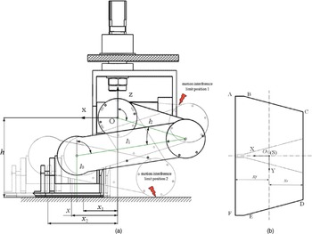
During parking, the base coordinate system O is established with the rotation center of the hip joint as the origin, and the coordinate axes of the system point in the same directions as the coordinate axes in S, as shown in Fig. 3. The schematic diagram of the leg mechanism is shown in Fig. 9(a). During the reconfiguration process of the robot, the support region for the robot remains unchanged and is always a closed convex polygon surrounded by the foot support region. The support mode in Fig. 2(b) was taken as the initial mode of the robot and considered with Fig. 3, and the support region of the robot during the reconfiguration process is shown in Fig. 9(b).
Schematic diagram of the optimal design of the foot landing position: (a) schematic of the leg mechanism and (b) support region for the reconfiguration process.

In Fig. 9(a), x is the horizontal distance between the foot landing position and the origin of O, h is the distance from the origin of O to the ground. In Fig. 9(b), the closed convex polygon ABCDEF is the support region in the robot’s reconfiguration process. S corresponds to the base coordinate system in Fig. 3, and its origin is also the center point, O
1, of the closed polygon ABCDEF.
 $x_{f}$
and
 $x_{r}$
are the front and rear boundaries of the support region along X, respectively, where
 $x_{f }$
= −
 $x_{r}$
= 102 mm.
Analysis of the landing motion of the supporting feet shows that, due to the structural design of the leg mechanism and the motion interference, there are two position limits in the X-direction, as shown in Fig. 9(a): the position limit,
 $x_{1}$
, determined by the interference between the thigh and the hip joint component, and the position limit,
 $x_{2}$
, determined by interference generated by the thigh and the ground. Thus,
 \begin{align} \begin{array}{c} x_{1}\leq x\leq x_{2}, \end{array}\end{align}
where
 $x_{1}=-90\,\mathrm{mm}$
and
 $x_{2}=210\,\mathrm{mm}$
.
Figure 9(a) shows that the relationship between the foot landing position and the initial angles
 $\theta _{1}^{0}$
,
 $\theta _{2}^{0}$
, and
 $\theta _{3}^{0}$
of the joints of the leg mechanism in the robot’s support mode are as follows:
 \begin{align} \begin{array}{c} \begin{cases} l_{0}+l_{1}\cos \theta _{1}^{0} -l_{2}\cos \theta _{3}^{0} =h\\[5pt] l_{1}\sin \theta _{1}^{0} -l_{2}\sin \theta _{3}^{0} =x\\[5pt] \theta _{2}^{0}=\theta _{3}^{0}-\theta _{1}^{0} \end{cases}, \end{array}\end{align}
where
 $\theta _{1}^{0}$
,
 $\theta _{2}^{0}$
, and
 $\theta _{3}^{0}$
are the angle between the calf rod and the Z-axis, the angle between the calf rod and the thigh rod, and the angle between the thigh rod and the Z-axis, respectively, when the robot is in support mode.
When
 $x$
is given, substituting it into (46) yields two sets of solutions for
 $\theta _{1}^{0}$
,
 $\theta _{2}^{0}$
, and
 $\theta _{3}^{0}$
. The solution with
 $\theta _{3}^{0}$
< 0 (the thigh is on the left side of the Z-axis) is discarded (due to restrictions of the thigh movement,
 $\theta _{3}^{0}$
is always positive).
The rotated angles of each joint of the leg mechanism during the reconfiguration process are as follows:
 \begin{align} \begin{array}{c} \begin{cases} \Delta \theta _{1}=\theta _{1}^{0}(x)\\[5pt] \Delta \theta _{2}=180^{\circ}-\theta _{2}^{0}(x)\\[5pt] \Delta \theta _{3}=\theta _{3}^{0}(x)-90^{\circ} \end{cases}. \end{array}\end{align}
The metamorphic robot’s reconfiguration involves movements on the sagittal plane, so the position of each component changes greatly along the X-axis. Therefore, during reconfiguration, with the deviation of the coordinates on the X-axis of the ZMP,
 $X_{zmp}(t,x)$
, from the center of the support region, as the evaluation metric to optimize the positions, the following optimization model for the foot landing position is obtained:
 \begin{align} \min f\left(x\right)=\int _{0}^{T}\left[X_{zmp}\left(t,x\right)-0\right]^{2}dt, \\[5pt] \mathrm{s}.\mathrm{t}.\begin{cases} x_{1}\leq x\leq x_{2}\\[5pt] x_{r}\leq X_{zmp}\left(t,x\right) \leq x_{f} \end{cases}, \end{align}
where the optimization variable x is the foot position in the horizontal direction in O in support mode,
 $X_{zmp}(t, x)$
is the value of
 $X_{zmp}$
of the robot with the foot landing position at x in the horizontal direction of O at time t, and T is the reconfiguration time.
The corresponding joint rotation angle
 $\theta _{i}$
can be calculated using (46), (47), and (43) based on the given foot landing position
 $x$
. By substituting
 $\theta _{i}$
into (26)–(33), the center of mass of each moving component of the robot can be obtained. By taking the second derivative, the acceleration of the center of mass of each moving component can be obtained. By substituting the position and acceleration of the center of mass of each moving component into (44) to calculate the ZMP,
 $X_{zmp}(t,x)$
can be obtained.
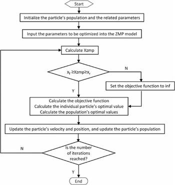
Equation (48) is a single-objective optimization problem, which can be optimized using particle swarm optimization (PSO) [Reference Kennedy and Eberhart31–Reference Yan, Lu, Liu and Deng34]. In this study, the number of particle swarms was selected as 20, the number of population update iterations was 800, the acceleration coefficients were both 2, and the optimal value was selected by linearly decreasing the inertia weight from 0.9 to 0.4. The flow chart of the PSO algorithm is shown in Fig. 10.
Flowchart of the particle swarm optimization (PSO) algorithm.

The optimal foot landing position was
 $x$
= 87.5 mm. Substituting this into (45) yields the rotation angles of the joints, when the robot was in support mode:
 $\theta _{1}^{0}$
= 17.5°,
 $\theta _{2}^{0}$
= 21.5°, and
 $\theta _{3}^{0}$
= 4°. Furthermore, the ZMP variation curve of the metamorphic robot during the reconfiguration process can be obtained, and the results are shown in Fig. 11.
Zero-moment point (ZMP) of the entire robot during the reconfiguration process after the optimization.

With the optimal foot landing, the changes of the centers of mass of the front frame and the entire robot are shown in Fig. 12. The comparison of the stability results before and after the optimization of the foot landing position are shown in Fig. 13. After the foot landing position was optimized, the ZMP was always inside the support region during the robot’s reconfiguration process. During the first 8 s of the reconfiguration process, compared with the unoptimized value, the optimized
 $X_{zmp}$
values were further away from the lower boundary of the support region and closer to the center of the support region. The results of
 $X_{zmp}$
before and after the optimization agreed only during the last 8–10 s of the reconfiguration process. Therefore, the optimized metamorphic robot was more stable during the reconfiguration process.
Trajectories of the centers of mass of the (a) front frame and (b) entire robot in the ZX plane.

 $X_{zmp}$
for the entire robot during the reconfiguration before and after the optimization.

5. Prototype test
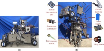
In order to further verify the validity and correctness of the above analysis, experimental verification was conducted based on the prototype metamorphic robot, and its reconstruction test process is shown in Fig. 14. The hardware control system of the metamorphic robot mainly included a PC host computer, main controller, sensor, and power supply module. The PC host computer was used as a human–computer interaction interface to monitor the running status of the robot and input the control parameters. The main controller was the core of the entire hardware control system, and it was mainly responsible for processing the robot’s sensor data and controlling the motion of each motor through the motor driver. The sensors mainly included joint angle sensors, angular velocity sensors, inertial measurement units (IMUs) that measured the robot posture information, and film pressure sensors (FSRs). The IMU used the MPU6050 gyroscope module, which could measure the acceleration of the moving object in the directions of the X-, Y-, and Z-axes and the angle or angular velocity around the X-, Y-, and Z-axes. IMUs were installed at the centers of mass of the front frame and the entire robot to measure the accelerations and pitch angles. Four FSRs were mounted between the foot end and the ground. The pressure information could be measured in real time through a film pressure sensor, and the measurement results could be transmitted to the main controller for ZMP position calculation [Reference Wang35]. The power supply required for the experiment was provided by the system power battery, and the power conversion module was used to supply power for each sensor and the joint motor driver.
Reconstruction test of the metamorphic robot: (a) car mode and (b) humanoid mode.

In the experiment, the acceleration information measured by the IMU was received and sent to the main controller for analysis and processing. The acceleration variation characteristics of the centers of mass of the end mechanism (front frame) and the entire robot were obtained, as shown in Fig. 15. During the experiment, the acceleration measurement results of the centers of mass of the front frame and the entire robot had similar trends to those of the simulation results presented in the previous section, which indicated that during the change from car mode to humanoid mode of the metamorphic robot, the center-of-mass position of the above two parts changed smoothly, and the overall movement process had good smoothness.
Acceleration of the centers of mass of the (a) front frame and (b) entire robot along the X- and Z-axes.

The variation curve of
 $X_{zmp}$
of the metamorphic robot during the reconstruction experiment was obtained from the pressure information measured by a thin-film pressure sensor and according to the ZMP calculation formula in the literature [Reference Wang35], as shown in Fig. 16.
 $X_{zmp}$
was always in the support domain, which indicated that the metamorphic robot did not collapse during the test. In addition, after the optimization of the supported foot landing position, the
 $X_{zmp}$
position of the system was closer to the center of the foot support domain, so the overall stability margin was significantly improved compared with that before optimization. The experimental results fully verified the effectiveness of the optimized design based on the stability.
 $X_{zmp}$
for the entire robot during the reconfiguration before and after the optimization.

In the test, the front frame pitch angle measured by the IMU was used to test the levelness of the front frame during the reconstruction process. The pitch angle curve of the front frame when reconstructed on a flat road is shown in Fig. 17.
Variation curve of front frame pitch angle.

It can be seen from Fig. 17 that although the pitch angle of the front frame of the metamorphic robot fluctuated during the reconstruction process, it generally varied between −0.3° and 0.2°, and the variation range was small. These small fluctuations were caused by the mechanical vibrations of the reconstruction process and the signal interference of the sensor. The above results proved the correctness of the designed horizontal lift model.
6. Conclusions
The metamorphic robot describe here is a novel ground mobile vehicle. Based on reconfigurability and wheeled–legged hybrid movement, the overall structural design of a metamorphic robot was analyzed, and its three configurations were described. Based on the structural design, the forward kinematics model of the robot’s reconfiguration process was established using screw theory. A level lifting mechanism was designed to meet the requirement that the front and rear frames must be held level during the reconfiguration process. Trajectory planning for the rotating joints was performed to ensure smooth motions during the reconfiguration. Meanwhile, the stability of the reconfiguration motion when the robot was parked was analyzed using the kinematics model. The stability of the reconfiguration of the system was further improved by optimizing the design of the support foot landing position. A mathematical model implemented in MATLAB and a prototype test were used to verify the effectiveness of the design in terms of motion smoothness and stability during the robot’s reconfiguration. This study lays a solid foundation for the stability control of the metamorphic robot during the parking reconfiguration process. In future research, to improve the stability of the metamorphic robot during the parking reconfiguration process, the center-of-mass adjusting slider is driven by servo motors to move rapidly in both lateral and longitudinal directions to change the ZMP position point of the system. According to the deviation degree between the actual ZMP and the ideal ZMP, the position of the center-of-mass adjusting slider is adjusted in real-time by using the stability control strategy, and then position of the center of mass of the whole robot is changed to maintain the ZMP curve near the center of the support region, which will greatly improve the stability of the system.
Financial support
This work was supported by the National Natural Science Foundation of China (Grant No. 51875148) and the Key Research and Development Program of Anhui Province (Grant No. 202104a05020040).
Conflicts of interest
The authors declare no conflicts of interest exist.
Ethical considerations
Not applicable.
Author contributions
Jun Liu conceived and designed the study and its methodology. Xiaodong Ruan conducted simulations, interpreted the results, and prepared this article manuscript under supervision by Jun Liu. The other authors provided assistance in writing the paper and in the experimental process.