1 Introduction
Experimental investigations have indicated that, in the case of a single bubble collapsing near a flat rigid wall, in a stationary liquid, an axial jet is formed that is directed towards the wall (Lauterborn & Bolle Reference Lauterborn and Bolle1975; Tomita & Shima Reference Tomita and Shima1986; Vogel, Lauterborn & Timm Reference Vogel, Lauterborn and Timm1989; Tomita & Shima Reference Tomita and Shima1990; Tong et al. Reference Tong, Schiffers, Shaw, Blake and Emmony1999; Brujan et al. Reference Brujan, Keen, Vogel and Blake2002; Lindau & Lauterborn Reference Lindau and Lauterborn2003; Brujan, Ikeda & Matsumoto Reference Brujan, Ikeda and Matsumoto2012; Reuter et al. Reference Reuter, Gonzales, Mettin and Ohl2017). Axial jet formation was also observed with bubbles collapsing near free, elastic, composite, or curved interfaces (Shima et al. Reference Shima, Tomita, Gibson and Blake1989; Tomita, Kodama & Shima Reference Tomita, Kodama and Shima1991; Brujan et al. Reference Brujan, Nahen, Schmidt and Vogel2001a ,Reference Brujan, Nahen, Schmidt and Vogel b ; Tomita et al. Reference Tomita, Robinson, Tong and Blake2002; Gregorcic, Petkovsek & Mozina Reference Gregorcic, Petkovsek and Mozina2007; Zhang et al. Reference Zhang, Yang, Tan and Wang2015), in the case of a buoyant bubble situated in a liquid of infinite extent (Benjamin & Ellis Reference Benjamin and Ellis1966; Zhang et al. Reference Zhang, Yang, Tan and Wang2015), for a bubble situated between a flat rigid wall and another bubble (Blake et al. Reference Blake, Robinson, Shima and Tomita1993), as well as for bubble pairs (Han et al. Reference Han, Kohler, Jungnickel, Mettin, Lauterborn and Vogel2015; Tomita & Sato Reference Tomita and Sato2017). Eventually, in the final stage of the collapse, a liquid–liquid impact occurs between the front of the re-entrant axial jet and the opposite side of the bubble, with the axial jet penetrating the slower-moving liquid close to the rigid wall, leading to the formation of a toroidal bubble. The shock waves emitted upon the collapse of the microbubbles generated during the collapse of the torus ring were demonstrated to be the main cause of cavitation erosion (Tomita & Shima Reference Tomita and Shima1986; Philipp & Lauterborn Reference Philipp and Lauterborn1998). Other factors that can contribute to the erosion of rigid materials are the impact of the re-entrant liquid jet onto the material surface and the shear forces acting along the wall surface (Hsiao et al. Reference Hsiao, Jayaprakash, Kapahi, Choi and Chahine2014; Chahine et al. Reference Chahine, Kapahi, Choi and Hsiao2016).
Theoretical and numerical research into bubble dynamics is well developed, starting in earnest with the study of the spherical collapse of a cavity by Lord Rayleigh (Reference Rayleigh1917). Stimulated by the early experimental studies on single bubble dynamics, whereupon it was realized that high-speed liquid jets can form and pierce the bubble, mathematical research focused on the development of numerical techniques to model the complex dynamics and highly deformed bubble shapes that result. The application of the boundary element method (BEM) by Blake and co-workers provided an efficient and accurate means of modelling jet formation for the case of a bubble situated near a rigid wall (Blake, Taib & Doherty Reference Blake, Taib and Doherty1986; Blake & Gibson Reference Blake and Gibson1989; Blake et al. Reference Blake, Robinson, Shima and Tomita1993; Tong et al. Reference Tong, Schiffers, Shaw, Blake and Emmony1999), free surface (Blake, Taib & Doherty Reference Blake, Taib and Doherty1987; Blake et al. Reference Blake, Hooton, Robinson and Tong1997), toroidal bubbles (Blake et al. Reference Blake, Hooton, Robinson and Tong1997) and bubbles situated in an axisymmetric stagnation flow (Robinson & Blake Reference Robinson, Blake and Blake1994). The success of this approach motivated a large number of investigators to employ the BEM to study a range of different bubble phenomena for various boundary conditions (see e.g. Zhang, Duncan & Chahine Reference Zhang, Duncan and Chahine1993; Klaseboer & Khoo Reference Klaseboer and Khoo2004; Brujan, Pearson & Blake Reference Brujan, Pearson and Blake2005; Klaseboer, Khoo & Hung Reference Klaseboer, Khoo and Hung2005; Fong et al. Reference Fong, Klaseboer, Turangan, Khoo and Hung2006; Lee, Klaseboer & Khoo Reference Lee, Klaseboer and Khoo2007; Wang, Duan & Wang Reference Wang, Duan and Wang2015; Li et al. Reference Li, Han, Zhang and Wang2016), and, to this day, it remains very popular.
Many realistic systems contain, however, three-dimensional (3D) configurations, and a more complicated dynamics of cavitation bubbles is expected to occur. Only a few cases of 3D configurations have been numerically investigated by using the BEM. Wang (Reference Wang1998, Reference Wang2004), Zhang et al. (Reference Zhang, Yeo, Khoo and Wang2001), Klaseboer et al. (Reference Klaseboer, Khoo and Hung2005), Jayaprakash, Hsiao & Chahine (Reference Jayaprakash, Hsiao and Chahine2012) and Zhang & Liu (Reference Zhang and Liu2015) simulated the collapse of a buoyant bubble oscillating near inclined and vertical rigid walls, Liu et al. (Reference Liu, Wang, Wang and Zhang2016) investigated the interaction of a bubble with a free surface near an inclined wall, while Wang & Manmi (Reference Wang and Manmi2014) and Wang, Manmi & Calvisi (Reference Wang, Manmi and Calvisi2015) examined the collapse of a bubble near a rigid wall subject to ultrasound propagating in a direction parallel to the wall. It was found that an inclined liquid jet is formed during bubble collapse and the jet direction is approximately the same as the direction of the bubble migration. However, with the exception of the studies by Klaseboer et al. (Reference Klaseboer, Khoo and Hung2005) and Zhang & Liu (Reference Zhang and Liu2015), the computations were not extended to the case of multiple connected domains and, thus, no details of the motion of the toroidal bubble, formed after the penetration of the liquid jet into the opposite bubble wall, were presented.
The present study describes, for the first time, experimental investigations of the dynamics of a laser-induced cavitation bubble situated near two perpendicular rigid walls. This situation belongs to the case of a bubble situated in two perpendicular pressure gradients, as each wall induces a secondary Bjerkness force on the bubble motion. The aim of the present work is to obtain specific information on the jetting behaviour of the bubble, the occurrence of secondary cavitation (tiny cavitation bubbles formed near the bubble surface where the jet is initiated), bubble migration, vortex ring formation and its motion during bubble oscillation. The temporal development of the bubble shape was examined by high-speed photography with
 $100\,000~\text{frames}~\text{s}^{-1}$
, and the significant parameters of this study are the relative position of the bubble with respect to each wall. We found a complex dynamics of the bubble, with the formation of an inclined jet, both radial and axial collapse of the torus ring formed after the penetration of the liquid jet into the opposite bubble surface, and a strong migration of the bubble towards the rigid walls. Our study is a step towards understanding the interaction of cavitation bubbles with rigid walls in 3D configurations. The present experimental observations reveal fundamental aspects of the behaviour of cavitation bubbles near two perpendicular rigid walls, which can be used as a basis for future experimental, theoretical and numerical investigations on the dynamics of cavitation bubbles, associated flow field and mechanisms of cavitation erosion in similar configurations. In particular, as will be shown later, numerical simulations that are able to cover a large part of the rebound phase of the bubble become essential for a better understanding of the complicated dynamics of the toroidal bubble. Beyond its fundamental significance, this study may have important implications for cavitation-mediated cleaning of rigid surfaces and can potentially introduce a new method for controlling the direction of the liquid jet and the subsequent behaviour of the vortex ring developed during bubble collapse.
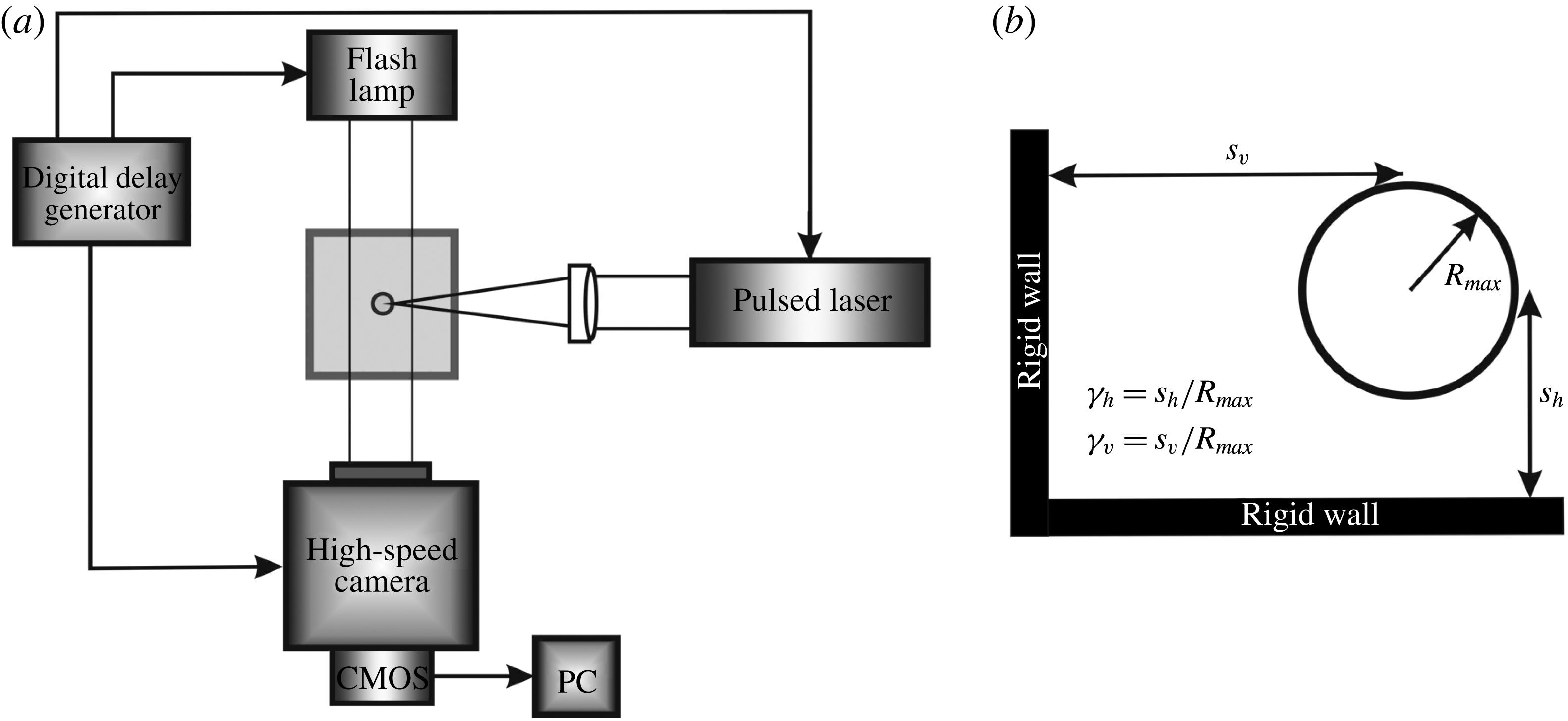
Experimental set-up for high-speed photography (a) and illustration of parameters governing the dynamics of a laser-induced cavitation bubble situated near two perpendicular rigid walls (b).

2 Experimental
Figure 1(a) shows a schematic diagram of the experimental set-up used to generate and photograph a cavitation bubble near two perpendicular rigid walls. Individual bubbles were generated in a glass cuvette filled with distilled water by using a Q-switched Nd:YAG laser (Spectra Physics Quanta Ray INDI, wavelength 1064 nm, and pulse duration 6 ns). The laser pulse is focused into the glass cuvette by a lens that is optimized to produce a short plasma length. The focused laser pulse ionizes the water, generating a breakdown plasma that is smaller than 100 nm in diameter and lasts for approximately 100 ns (Vogel, Busch & Parlitz Reference Vogel, Busch and Parlitz1996). The energy deposited then appears as an expanding bubble, with the gas inside the bubble consisting primarily of the ionization products – atomic hydrogen and oxygen – and, possibly, water vapour. The rigid walls, made of aluminium with a thickness of 10 mm, are inserted from the top of the glass cuvette using adjustable positioners. The test section was positioned in such a way that the bubbles are generated at the centre of the test chamber. The dynamics of the cavitation bubble were recorded with a high-speed camera (Photron Fastcam SA 1.1) at framing rates
 $100\,000~\text{frames}~\text{s}^{-1}$
with an exposure time of 500 ns. The image on the fluorescent screen was recorded with a complementary metal–oxide–semiconductor (CMOS) camera system. The signal from the CMOS camera was then digitized with 8-bit resolution and passed to a computer. In all the experiments performed, the resolution was
 $14~\unicode[STIX]{x03BC}\text{m}~\text{pixel}^{-1}$
. For illumination, a flash lamp with 500 ms flash duration was used that covered the most relevant part of the interaction. The timing of the photography was adjusted with an electronic delay circuit. The bubble was photographed in side view and also in top view by illuminating the bubble through a Plexiglas wall used as horizontal wall.
The significant parameters of this study are the relative position of the bubble with respect to the rigid walls. The maximum bubble radius and the distance
 $s$
between the laser focus and a wall yield the non-dimensional stand-off parameter
 $\unicode[STIX]{x1D6FE}=s/R_{max}$
. The non-dimensional distance of the bubble from the horizontal wall is denoted by
 $\unicode[STIX]{x1D6FE}_{h}=s_{h}/R_{max}$
, while the non-dimensional distance of the bubble from the vertical wall is denoted by
 $\unicode[STIX]{x1D6FE}_{v}=s_{v}/R_{max}$
(figure 1
b). The investigations are restricted to values of the
 $\unicode[STIX]{x1D6FE}_{h}$
and
 $\unicode[STIX]{x1D6FE}_{v}$
parameters larger than 1. For smaller values, the exposure time for each frame is too large to capture the details of the bubble motion. For all values of
 $\unicode[STIX]{x1D6FE}_{h}$
and
 $\unicode[STIX]{x1D6FE}_{v}$
, the maximum bubble radius was held constant at a value
 $R_{max}=0.78\pm 0.05~\text{mm}$
. Note that, for both
 $\unicode[STIX]{x1D6FE}_{h}$
and
 $\unicode[STIX]{x1D6FE}_{v}$
values close to 1, where the bubble at its maximum expansion is non-spherical,
 $R_{max}$
represents the radius of a spherical bubble with the same volume (equivalent spherical radius). We assumed that the maximum bubble volume does not change with variation of
 $\unicode[STIX]{x1D6FE}_{h}$
and
 $\unicode[STIX]{x1D6FE}_{v}$
. The equivalent spherical radius is, hence, assumed to be independent of
 $\unicode[STIX]{x1D6FE}_{h}$
and
 $\unicode[STIX]{x1D6FE}_{v}$
for constant laser pulse energy. We also note that for such small bubbles the effect of buoyancy is negligible.
3 Bubble dynamics
We shall now examine the behaviour of a laser-induced cavitation bubble generated near two perpendicular rigid walls. We investigated the influence of the relative distance between bubble and each wall, defined by the non-dimensional stand-off parameters
 $\unicode[STIX]{x1D6FE}_{h}$
and
 $\unicode[STIX]{x1D6FE}_{v}$
, on the temporal evolution of the bubble shape, jet formation and bubble migration towards the rigid walls. In all photographic series the vertical wall is located on the left-hand side of the frames while the horizontal wall is located at the bottom of the frames. The first frame was taken
 $10~\unicode[STIX]{x03BC}\text{s}$
after the moment of optical breakdown and the laser pulse comes from the right.
3.1 Jet formation and bubble migration
The motion of the jet developed during bubble collapse and the bubble migration are presented for three values of the stand-off distance between the bubble centre at formation and the horizontal wall, namely
 $\unicode[STIX]{x1D6FE}_{h}\approx 2.5$
,
 $\unicode[STIX]{x1D6FE}_{h}\approx 1.9$
and
 $\unicode[STIX]{x1D6FE}_{h}\approx 1$
. For each
 $\unicode[STIX]{x1D6FE}_{h}$
value, the bubble motion is illustrated for very large values of the stand-off parameter
 $\unicode[STIX]{x1D6FE}_{v}$
, where the influence of the vertical wall is only minor, intermediate
 $\unicode[STIX]{x1D6FE}_{v}$
values, where the influence of the vertical wall becomes pronounced, and
 $\unicode[STIX]{x1D6FE}_{h}\approx \unicode[STIX]{x1D6FE}_{v}$
, where the bubble is generated at almost equal distances from the perpendicular rigid walls and the influence of the rigid walls are equally strong.
3.1.1 Bubble behaviour for
 $\unicode[STIX]{x1D6FE}_{h}\approx 2.5$

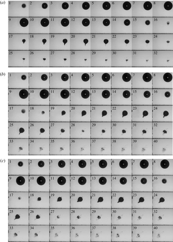
Figure 2 illustrates the growth and collapse of a bubble generated near two perpendicular rigid walls for a value of the non-dimensional stand-off parameter
 $\unicode[STIX]{x1D6FE}_{h}\approx$
2.5. For
 $\unicode[STIX]{x1D6FE}_{h}=2.59$
and
 $\unicode[STIX]{x1D6FE}_{v}=15.25$
(figure 2
a), the bubble remains spherical during growth (frames 1–10) and most of the first collapse phase (frames 11–16). A thin liquid jet develops in the very late stage of the first bubble collapse (frame 16) that penetrates the opposite bubble wall, causing a funnel-shaped protrusion that is clearly visible in the rebound phase of the bubble (frames 17–23). Unlike the case of the bubble situated near a single rigid wall, where the jet is directed perpendicular to the wall, the jet is slightly inclined towards the vertical wall. The penetration of the liquid jet into the opposite bubble surface changes the topology of the bubble and the bubble takes a toroidal shape. Although the bubble migrates mostly towards the horizontal wall, there is no contact between the toroidal bubble and this wall in the time interval investigated here.
When the bubble is generated closer to the vertical wall (
 $\unicode[STIX]{x1D6FE}_{h}=2.43$
and
 $\unicode[STIX]{x1D6FE}_{v}=3.32$
, figure 2
b), the inclination of the jet with respect to a vertical plane increases and the migration of the bubble towards the vertical wall is more pronounced. The toroidal bubble shape, which is also inclined towards the vertical wall, and its oscillation are now clearly visible during the third and fourth oscillation cycles of the bubble (frames 33–40). The torus plane is perpendicular to the direction of the protrusion induced by the liquid jet. As in the previous case, there is no impact of the liquid jet onto the rigid walls and no contact of the toroidal bubble with the horizontal wall even at the end of the fourth oscillation period of the bubble.
Figure 2(c), which illustrates the bubble dynamics for
 $\unicode[STIX]{x1D6FE}_{h}=2.48$
and
 $\unicode[STIX]{x1D6FE}_{v}=2.7$
, corresponds to the case when the bubble is situated at almost equal distances from the rigid walls. The liquid jet developed during bubble collapse is now inclined at a value of approximately
 $45^{\circ }$
and the bubble migrates equally towards each wall. A tubular structure is visible on the top of the bubble (starting with frame 18), which was identified by Lindau & Lauterborn (Reference Lindau and Lauterborn2003) as secondary cavitation. This is a consequence of the shock wave emitted during jet impact onto the opposite bubble surface, which is reflected as a tension wave at the jet boundary. The tension wave propagates backwards to the jet motion and interacts with the gas nuclei that are present in the liquid surrounding the bubble, leading to the formation of microbubbles at the bubble surface where the jet was initiated (Lindau & Lauterborn Reference Lindau and Lauterborn2003). We also note that the inclination of this tubular structure coincides with that of the funnel-shaped protrusion caused by the liquid jet.
Dynamics of a cavitation bubble situated near two perpendicular rigid walls for
 $\unicode[STIX]{x1D6FE}_{h}\approx 2.5$
(side view): (a)
 $\unicode[STIX]{x1D6FE}_{h}=2.59$
,
 $\unicode[STIX]{x1D6FE}_{v}=15.25$
,
 $R_{max}=0.78~\text{mm}$
; (b)
 $\unicode[STIX]{x1D6FE}_{h}=2.43$
,
 $\unicode[STIX]{x1D6FE}_{v}=3.32$
,
 $R_{max}=0.83~\text{mm}$
; (c)
 $\unicode[STIX]{x1D6FE}_{h}=2.48$
,
 $\unicode[STIX]{x1D6FE}_{v}=2.7$
,
 $R_{max}=0.82~\text{mm}$
. Frame interval
 $10~\unicode[STIX]{x03BC}\text{s}$
. Frame width 3.65 mm.

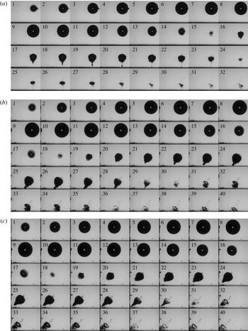
Dynamics of a cavitation bubble situated near two perpendicular rigid walls for
 $\unicode[STIX]{x1D6FE}_{h}\approx$
1.9 (side view): (a)
 $\unicode[STIX]{x1D6FE}_{h}=2.04$
,
 $\unicode[STIX]{x1D6FE}_{v}=15.04$
,
 $R_{max}=0.76~\text{mm}$
; (b)
 $\unicode[STIX]{x1D6FE}_{h}=1.87$
,
 $\unicode[STIX]{x1D6FE}_{v}=2.81$
,
 $R_{max}=0.83~\text{mm}$
; (c)
 $\unicode[STIX]{x1D6FE}_{h}=1.87$
,
 $\unicode[STIX]{x1D6FE}_{v}=1.92$
,
 $R_{max}=0.83~\text{mm}$
. Frame interval
 $10~\unicode[STIX]{x03BC}\text{s}$
. Frame width 3.5 mm.

3.1.2 Bubble behaviour for
$\unicode[STIX]{x1D6FE}_{h}\approx 1.9$

Figure 3 illustrates the bubble behaviour when the value of the stand-off parameter defined with respect to the horizontal wall is reduced to
 $\unicode[STIX]{x1D6FE}_{h}\approx 1.9$
. For
 $\unicode[STIX]{x1D6FE}_{h}=2.04$
and
 $\unicode[STIX]{x1D6FE}_{v}=15.04$
(figure 3
a), there is only a minor influence of the vertical wall on the dynamical characteristics of the bubble and the bubble behaviour is very similar to that near a single rigid wall. During collapse, the bubble becomes elongated in a direction perpendicular to the horizontal wall, it migrates mostly towards this wall, and a liquid jet directed towards the horizontal wall is developed, which leads to the protrusion of the bubble surface facing the wall. The jet impacts the horizontal wall during the second oscillation period of the bubble (frame 21) and the torus touches the horizontal wall in the fourth cycle of bubble oscillation (frames not shown). The damage potential of the jet and toroidal bubble is only minor because, on the one hand, the liquid jet is strongly decelerated on its way to the horizontal wall by the liquid layer situated between bubble and wall and, on the other hand, most of the torus energy is lost during its first, second and third collapse.
For
 $\unicode[STIX]{x1D6FE}_{h}=1.87$
and
 $\unicode[STIX]{x1D6FE}_{v}=2.81$
(figure 3
b), the liquid jet formed during bubble collapse is inclined towards the vertical wall and impacts the horizontal wall during the first bubble rebound (frames 26–29). During impact, the jet is further deflected towards the vertical wall. The toroidal bubble gradually touches the horizontal wall in the fourth oscillation cycle of the bubble, starting with the torus part situated farthest from the vertical wall (frames 38–40). The second cavity that is visible below the torus ring in frames 30–35 is the result of the jet impact onto the opposite bubble surface. A part of the gas inside the bubble is dragged along with the jet and separates from the bubble, forming a new cavity. A second vortex ring is generated by this cavity (frames 34–36), which touches the horizontal rigid wall near the conclusion of the third oscillation period of the bubble. Two vortex rings generated during the collapse of a single bubble were also observed by Zhang et al. (Reference Zhang, Yang, Tan and Wang2015) in the case of buoyant bubbles collapsing above a horizontal rigid wall.
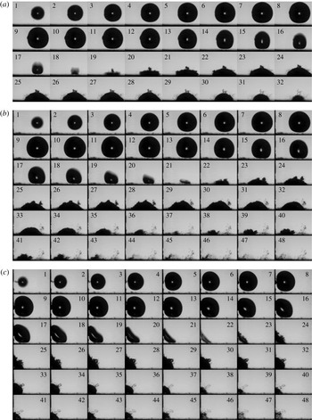
Dynamics of a cavitation bubble situated near two perpendicular rigid walls for
 $\unicode[STIX]{x1D6FE}_{h}\approx 1.1$
(side view): (a)
 $\unicode[STIX]{x1D6FE}_{h}=1.11$
,
 $\unicode[STIX]{x1D6FE}_{v}=15.25$
,
 $R_{max}=0.83~\text{mm}$
; (b)
 $\unicode[STIX]{x1D6FE}_{h}=1.08$
,
 $\unicode[STIX]{x1D6FE}_{v}=2.17$
,
 $R_{max}=0.85~\text{mm}$
; (c)
 $\unicode[STIX]{x1D6FE}_{h}=1.08$
,
 $\unicode[STIX]{x1D6FE}_{v}=0.88$
,
 $R_{max}=0.85~\text{mm}$
. Frame interval
 $10~\unicode[STIX]{x03BC}\text{s}$
. Frame width 3 mm.

For
 $\unicode[STIX]{x1D6FE}_{h}=1.87$
and
 $\unicode[STIX]{x1D6FE}_{v}=1.92$
(figure 3
c, and see the supplementary material, movie 1, available at https://doi.org/10.1017/jfm.2018.82), where the bubble is generated equally distant from the rigid walls, the liquid jet formed during bubble collapse and the bubble migration are directed towards the corner made by the two walls, and the toroidal bubble touches both walls almost simultaneously. No impact of the jet onto the corner was observed. The jet impact might have occurred between frames 28 and 29, but the frame rate is too low for such a phenomenon to be observed. The secondary cavitation structure is also generated and, again, its inclination coincides with that of the conical protrusion generated after the penetration of the liquid jet into the opposite bubble surface. As in the previous case, a second, smaller vortex ring is generated during the third oscillation period of the bubble (frames 36–40).
3.1.3 Bubble behaviour for
$\unicode[STIX]{x1D6FE}_{h}\approx 1$

Figure 4 illustrates the behaviour of the bubble for
 $\unicode[STIX]{x1D6FE}_{h}\approx 1$
. At
 $\unicode[STIX]{x1D6FE}_{h}=1.11$
and
 $\unicode[STIX]{x1D6FE}_{v}=15.25$
(figure 4
a), the bubble dynamics resembles that near a single rigid wall (Vogel et al.
Reference Vogel, Lauterborn and Timm1989; Philipp & Lauterborn Reference Philipp and Lauterborn1998). The expansion of the bubble is spherical in an early stage of its growth and, at the maximum volume (corresponding to frame 10), the bubble part closer to the horizontal wall becomes slightly flattened. During first collapse (frames 11–18), the bubble becomes elongated in a direction perpendicular to the horizontal rigid wall and a liquid jet develops near the end of the collapse (frame 17). Since the jet is not decelerated by the liquid layer situated between bubble and rigid wall, a higher damage potential of the jet is expected in this case as compared to larger
 $\unicode[STIX]{x1D6FE}_{h}$
values. The jet flow inside the bubble cannot be directly visualized because of the opaqueness of the bubble surface but its formation can be inferred from the presence of the secondary cavitation structure at the upper part of the bubble, which is visible starting with frame 19. The bubble remains in contact with the horizontal wall during rebound and following oscillation periods. There is also a slight migration of the bubble towards the vertical rigid wall that can be more clearly observed in the movie format of this figure (see supplementary material, movie 2).
When the bubble is generated closer to the vertical rigid wall (
 $\unicode[STIX]{x1D6FE}_{h}=1.08$
and
 $\unicode[STIX]{x1D6FE}_{v}=2.17$
, figure 4
b), the formation of the liquid jet starts earlier during first bubble collapse as indicated by the involution of the upper-right surface of the bubble (frames 18–20). The liquid jet leads to the formation of a toroidal bubble that has a small inclination with respect to the horizontal rigid wall (frame 21). The rebound phase is characterized by a strong migration of the bubble towards the vertical wall and the bubble almost touches the vertical wall in the fourth oscillation period. Examination of the movie format of this photographic sequence indicates that the bubble is bouncing on its motion towards the vertical wall (see supplementary material, movie 3).
The behaviour of a bubble generated at almost equal distances from both rigid walls is shown in figure 4(c) (
 $\unicode[STIX]{x1D6FE}_{h}=1$
and
 $\unicode[STIX]{x1D6FE}_{v}=0.88$
). The bubble surfaces facing the rigid walls are flattened during the growth phase (frames 5–10). The bubble surface opposite the corner collapses faster, while the bubble surface facing the corner is almost motionless, and the bubble achieves a disc-like shape in the final stage of the collapse (frames 21 and 22). The secondary cavitation structure is observed in the rebound phase of the bubble (starting with frame 24). The occurrence and the inclination of the secondary cavitation structure suggests that a liquid jet is formed inside the bubble that impacts the opposite bubble surface and the liquid jet is inclined at an angle of
 $45^{\circ }$
. It is interesting to note that, although the bubble is generated very close to both rigid walls, there is no direct impact of the liquid jet onto the corner made by the two walls, as there is still a volume of liquid in the close proximity of the corner. The jet impact onto the corner occurs in the rebound phase of the bubble (frame 26), approximately
 $40~\unicode[STIX]{x03BC}\text{s}$
after the bubble reaches the minimum volume (frame 22). The bubble then oscillates in the form of a torus that disintegrates into tiny bubbles in the fourth oscillation period (frames 46–48).
Figure 4 also demonstrates that the second, vertical rigid wall induces a prolongation of the oscillation period of the bubble in comparison to the case of a bubble oscillating near a single rigid wall. The smaller the distance between bubble and vertical wall, the larger is the oscillation period of the bubble. For
 $\unicode[STIX]{x1D6FE}_{v}=2.17$
(figure 4
b) the oscillation period is at least
 $20~\unicode[STIX]{x03BC}\text{s}$
larger than that for
 $\unicode[STIX]{x1D6FE}_{v}=15.25$
(figure 4
a) (as the bubble achieves its minimum volume around frame 18 in figure 4(a) and around frame 21 in figure 4
b). This difference increases to approximately
 $30~\unicode[STIX]{x03BC}\text{s}$
for
 $\unicode[STIX]{x1D6FE}_{v}=0.88$
(figure 4
c) (as the moment of collapse is around frame 22).
3.2 Toroidal bubble dynamics
For relatively large values of the stand-off parameter
 $\unicode[STIX]{x1D6FE}_{h}$
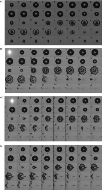
, the motion of the toroidal bubble can be easily followed from the photographic sequences taken in side view. The situation is quite different for a bubble generated very close to the horizontal wall. In this case, the bubble touches the horizontal wall during its oscillation and the side view photography gives only limited information on the dynamics of the toroidal bubble generated after the penetration of the liquid jet into the opposite bubble surface. The photographic sequences in figure 5 show the growth and collapse of a bubble for
 $\unicode[STIX]{x1D6FE}_{h}\approx 1$
in top view, through the horizontal wall. Figure 5(a) (see also supplementary material, movie 4) shows the case of a bubble situated near two perpendicular rigid walls for
 $\unicode[STIX]{x1D6FE}_{h}=1$
and
 $\unicode[STIX]{x1D6FE}_{v}=16.8$
. There is no influence of the vertical wall and the behaviour of the bubble is very similar to that near a single rigid wall (Vogel et al.
Reference Vogel, Lauterborn and Timm1989; Philipp & Lauterborn Reference Philipp and Lauterborn1998; Lindau & Lauterborn Reference Lindau and Lauterborn2003). The bubble expands to a maximum size of
 $R_{max}=0.83~\text{mm}$
and subsequently starts to collapse, developing a liquid jet, which is directed towards the horizontal wall. The liquid jet penetrates into the bubble, and between frames 18 and 19 impacts on the horizontal wall, producing a toroidal bubble shape. The torus expands during the rebound phase and then collapses in a radial direction along its entire circumference. Near the third collapse, the torus disintegrates into many microbubbles (frame 37) that oscillate almost simultaneously (frames 38–40).
Dynamics of a cavitation bubble situated near two perpendicular rigid walls for
 $\unicode[STIX]{x1D6FE}_{h}\approx 1$
(top view): (a)
 $\unicode[STIX]{x1D6FE}_{h}=1$
,
 $\unicode[STIX]{x1D6FE}_{v}=16.8$
,
 $R_{max}=0.82~\text{mm}$
; (b)
 $\unicode[STIX]{x1D6FE}_{h}=0.97$
,
 $\unicode[STIX]{x1D6FE}_{v}=4.11$
,
 $R_{max}=0.73~\text{mm}$
; (c)
 $\unicode[STIX]{x1D6FE}_{h}=1$
,
 $\unicode[STIX]{x1D6FE}_{v}=2.59$
,
 $R_{max}=0.71~\text{mm}$
; (d)
 $\unicode[STIX]{x1D6FE}_{h}=0.97$
,
 $\unicode[STIX]{x1D6FE}_{v}=1.87$
,
 $R_{max}=0.73~\text{mm}$
. Frame interval
 $10~\unicode[STIX]{x03BC}\text{s}$
. Frame width 2.57 mm.

Figure 5(b) (see also supplementary material, movie 5) illustrates the behaviour of the bubble situated near two perpendicular rigid walls for
 $\unicode[STIX]{x1D6FE}_{h}=0.97$
and
 $\unicode[STIX]{x1D6FE}_{v}=4.11$
, where the liquid jet formed during bubble collapse is inclined towards the vertical rigid wall (situated on the left-hand side of the bubble but outside the photographic frames). We first note that the formation of the liquid jet starts very early during the collapse phase of the bubble. It can be seen in the bright spot of the bubble centre (frames 16 and 17) approximately
 $20~\unicode[STIX]{x03BC}\text{s}$
before the bubble reaches the minimum volume (frame 18). The penetration of the liquid jet into the opposite bubble surface results in the formation of a toroidal bubble shape as well, which reaches its maximum volume around frame 24. The dark spot visible in the bright centre of the torus in frames 19–28 is the secondary cavitation structure. The collapse phase of the torus (frames 25–29) is, however, very different from the case of a bubble situated near a single rigid wall. The torus now starts to collapse from its part situated farthest from the vertical wall, and the implosion propagates around the torus, in both directions, towards the opposite end of the torus (frames 28–29). At the same time, the torus part situated closest to the vertical wall implodes much slower in a radial direction (i.e. the radius of the torus tube decreases). This leads to the formation of a single cavity at the end of the second oscillation period that appears to keep an almost spherical shape during rebound (frames 30–33). Notably, there is a strong migration of the bubble towards the vertical wall as the centre of the resulting cavity in frame 30 is situated 0.68 mm away from the initial location of the bubble.
With decreasing distance between the bubble and the vertical wall, the basic mechanisms are the same but the magnitude and starting times of some individual components change. The toroidal implosion starts earlier with decreasing distance between bubble and vertical wall. The pinch-off of the torus part opposite to the vertical wall, which initiates the collapse in the toroidal direction, can be observed just before the torus reaches its maximum volume for
 $\unicode[STIX]{x1D6FE}_{v}=2.59$
(figure 5
c, frame 24) and very early in the rebound phase of the bubble for
 $\unicode[STIX]{x1D6FE}_{v}=1.87$
(figure 5
d, frame 22). The gas inside the torus is thus pushed towards the opposite part of the torus, slowing down the radial collapse of the torus part situated closest to the vertical wall. Subsequently, the resulting cavity obtained at the instant of the second collapse increases in size. It has the shape of a torus sector whose central angle (the angle formed at the centre of the torus by the radii touching the extremities of the torus sector) increases with decreasing
 $\unicode[STIX]{x1D6FE}_{v}$
. For the case illustrated in figure 5(c), the central angle is approximately
 $90^{\circ }$
(frame 30) and increases to approximately
 $130^{\circ }$
for the case shown in figure 5(d) (frame 32). This trend continues with decreasing
 $\unicode[STIX]{x1D6FE}_{v}$
, and in the limit
 $\unicode[STIX]{x1D6FE}_{h}=\unicode[STIX]{x1D6FE}_{v}$
the bubble collapses again with a toroidal shape (figure 4
c). As before, a strong migration of the bubble towards the vertical wall is observed. The centre of the cavity near the instant of the second collapse is situated approximately 0.73 mm away from the initial bubble location for
 $\unicode[STIX]{x1D6FE}_{v}=2.59$
, while the corresponding value for
 $\unicode[STIX]{x1D6FE}_{v}=1.87$
is 1 mm. We also note that, for
 $\unicode[STIX]{x1D6FE}_{v}=2.59$
and
 $\unicode[STIX]{x1D6FE}_{v}=1.87$
, where the jet is significantly inclined, the secondary cavitation structure is seen as a dark stripe situated at the bubble part most distant from the vertical rigid wall (starting with frame 18 in figure 5
c and with frame 19 in figure 5
d). All these phenomena can be clearly visualized in the supplementary material, movie 6, for figure 5
c, and movie 7, for figure 5(d).
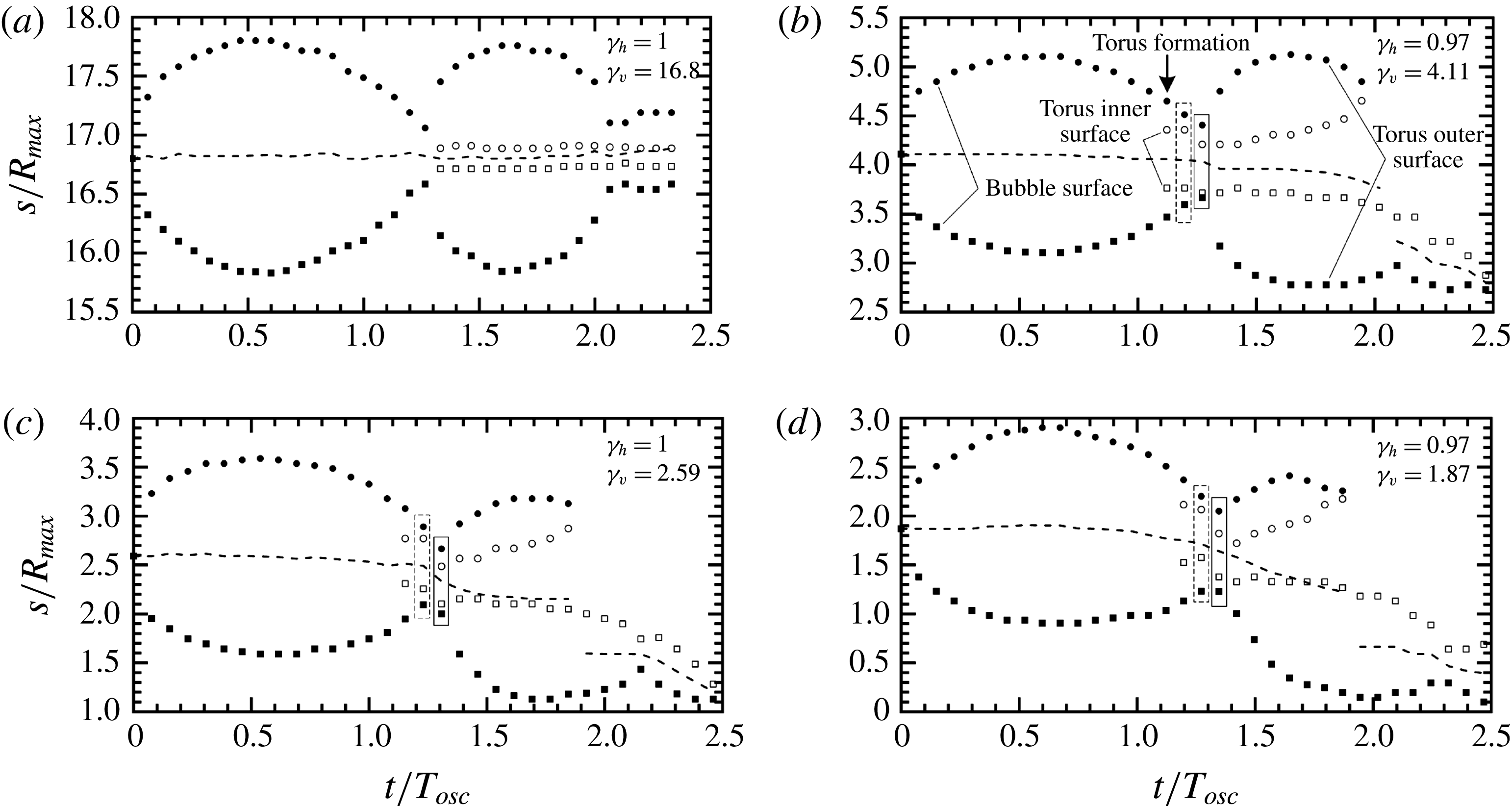
Time histories of the dimensionless distances of the outer and inner surfaces of the bubble from the vertical rigid wall for
 $\unicode[STIX]{x1D6FE}_{h}\approx 1$
: (a)
 $\unicode[STIX]{x1D6FE}_{h}=1$
,
 $\unicode[STIX]{x1D6FE}_{v}=16.8$
,
 $R_{max}=0.82~\text{mm}$
; (b)
 $\unicode[STIX]{x1D6FE}_{h}=0.97$
,
 $\unicode[STIX]{x1D6FE}_{v}=4.11$
,
 $R_{max}=0.73~\text{mm}$
; (c)
 $\unicode[STIX]{x1D6FE}_{h}=1$
,
 $\unicode[STIX]{x1D6FE}_{v}=2.59$
,
 $R_{max}=0.71~\text{mm}$
; (d)
 $\unicode[STIX]{x1D6FE}_{h}=0.97$
,
 $\unicode[STIX]{x1D6FE}_{v}=1.87$
,
 $R_{max}=0.73~\text{mm}$
. The filled symbols indicate the outer surface of the bubble (▪, outer bubble surface closest to the vertical rigid wall; ●, outer bubble surface most distant from the vertical rigid wall) while the open symbols indicate the inner surface of the toroidal ring formed after the penetration of the liquid jet into the opposite bubble surface (▫, inner torus surface closest to the vertical rigid wall; ○, inner torus surface most distant from the vertical rigid wall).

Figure 6 shows the time history of the dimensionless distance of the closest and most distant points on the bubble surface, including the inner surface of the torus ring, from the vertical rigid wall, for the cases illustrated in figure 5. Also included in figure 6 is the bubble’s outer surface centreline, which gives an indication of the bubble migration towards the vertical wall. The time is normalized by the oscillation period of a bubble situated in a liquid of infinite extent,
 $T_{osc}=1.83R_{max}(\unicode[STIX]{x1D70C}_{\infty }/p_{\infty })^{1/2}$
, where
 $\unicode[STIX]{x1D70C}_{\infty }$
is the liquid density (
 $\unicode[STIX]{x1D70C}_{\infty }=10^{3}~\text{kg}~\text{m}^{-3}$
) and
 $p_{\infty }$
the static pressure of the liquid (
 $p_{\infty }=10^{5}~\text{N}~\text{m}^{-2}$
). The points highlighted with the dashed rectangle belong to the collapse phase of the bubble, while those highlighted by the solid rectangle belong to the rebound phase of the bubble. For
 $\unicode[STIX]{x1D6FE}_{h}=1$
and
 $\unicode[STIX]{x1D6FE}_{v}=16.8$
(figure 6
a), the motion of the outer surface of the bubble is symmetrical, the inner diameter of the torus ring is almost constant during the second oscillation period of the bubble, and there is no migration of the bubble towards the vertical rigid wall.
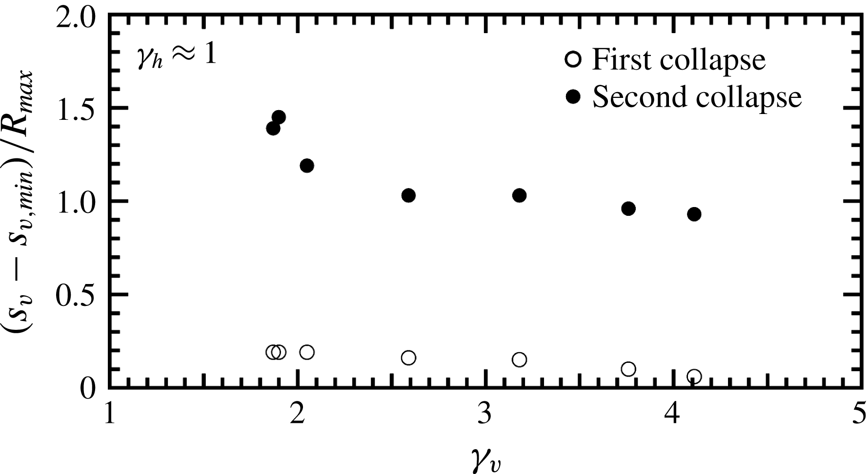
Dimensionless distance covered by the bubble during its migration towards the vertical wall for
 $\unicode[STIX]{x1D6FE}_{h}\approx 1$
. Here
 $s_{v,min}$
denotes the position of the bubble centroid at the moment of first (open symbols) and second (filled symbols) collapse. For the second bubble collapse,
 $s_{v,min}$
denotes the position of the centre of the torus part situated closest to the vertical rigid wall.

An asymmetric torus ring is developed when the bubble collapses closer to the vertical wall as a consequence of an inclined jet formation (figure 6
b–d). In the collapse phase, the cross-section of the torus part situated closer to the vertical wall (i.e. in the direction of the jet formed during bubble collapse) is thicker than the opposite part, and this difference increases with decreasing
 $\unicode[STIX]{x1D6FE}_{v}$
. The cross-section of the torus part nearest to the vertical wall for
 $\unicode[STIX]{x1D6FE}_{v}=4.11$
(figure 6
b) is a factor of 1.13 larger than that of the torus part opposite to the vertical wall, while the corresponding value for
 $\unicode[STIX]{x1D6FE}_{v}=1.87$
(figure 6
d) is 2.57. Interestingly, the rebound starts from the torus part situated farthest from the vertical wall. At later times, however, the rebound of the torus part situated closer to the vertical wall becomes dominant. This is mainly due to a rapid motion of the outer surface of the torus part nearest to the vertical wall (indicated by the filled square symbols) while its inner surface (indicated by the open square symbols) is almost motionless. For
 $\unicode[STIX]{x1D6FE}_{v}=1.87$
, the rebound of the bubble part facing the vertical rigid wall is so strong that its outer surface almost touches the vertical wall at the maximum expansion. In contrast, the inner surface of the torus part opposite to the vertical wall (indicated by the open circle symbols) moves away from this wall for the entire part of the second oscillation period of the bubble. These dynamical features of the torus oscillation are barely visible for
 $\unicode[STIX]{x1D6FE}_{v}=4.11$
but become particularly prominent for
 $\unicode[STIX]{x1D6FE}_{v}=1.87$
. The motion in opposite directions of the inner and outer surfaces of the torus part most distant from the vertical wall, which can be observed for
 $t/T_{osc}>1.6$
, leads eventually to the pinch-off of this torus part. Once the collapse in the toroidal direction has occurred, the bubble migrates significantly towards the vertical wall.
Figure 7 shows the distance covered by the bubble during its migration towards the vertical wall, determined with respect to the moment of the first and second collapse, for
 $\unicode[STIX]{x1D6FE}_{h}\approx 1$
. The bubble migration is larger for smaller
 $\unicode[STIX]{x1D6FE}_{v}$
values and is more pronounced during the second oscillation period of the bubble. The maximum migration distance was found to be 1.1 mm for
 $\unicode[STIX]{x1D6FE}_{v}=1.9$
. We also note that, for
 $\unicode[STIX]{x1D6FE}_{v}$
smaller than 1.85, the bubble touches the vertical wall before reaching its maximum volume in the second oscillation period and, subsequently, the maximum pressure and temperature generated inside the bubble at its minimum volume act on both rigid walls.
3.3 Jet inclination
The jet inclination was determined as the inclination of the conical protrusion formed after the penetration of the liquid jet into the opposite bubble surface. It was measured in the rebound phase of the bubble, where the protrusion is well developed, and before the impact of the jet onto the horizontal wall. The secondary cavitation structure, which occurs at the bubble surface where the jet is initiated, was also used in measuring the jet inclination, as this structure has the same inclination as that of the liquid jet. Whenever possible the jet inclination was verified against the inclination of the torus ring, since the conical protrusion with the jet inside is perpendicular to the torus plane. We restricted the measurements only to values of the non-dimensional stand-off parameter
 $\unicode[STIX]{x1D6FE}_{h}>1.5$
. For smaller
 $\unicode[STIX]{x1D6FE}_{h}$
values, the jet impacts the horizontal wall in a very early stage of bubble rebound, it is deflected towards the vertical wall, and the jet inclination cannot be accurately measured.
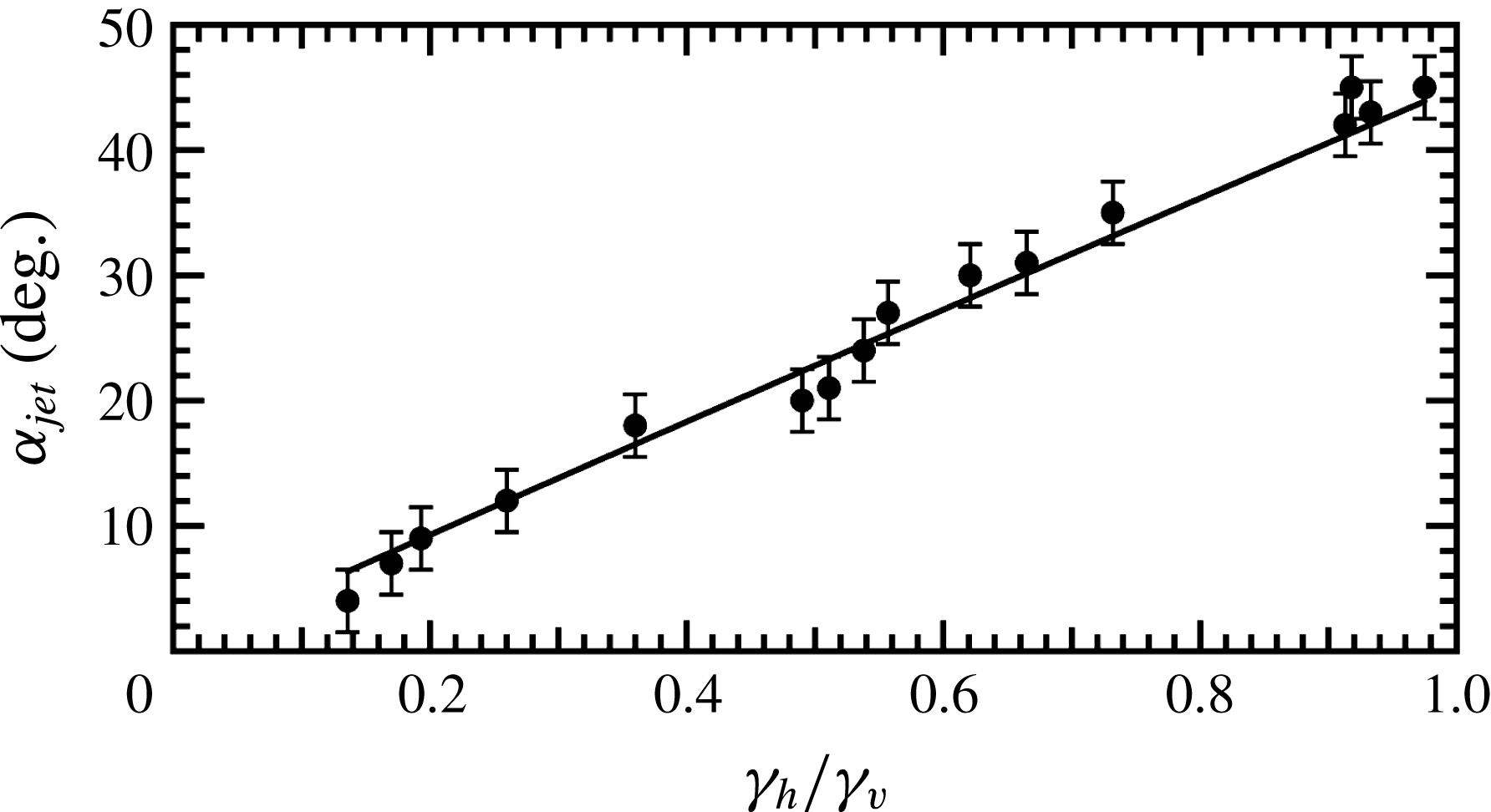
Figure 8 shows the inclination of the liquid jet formed during bubble collapse towards the vertical wall,
 $\unicode[STIX]{x1D6FC}_{jet}$
, as a function of the ratio between the non-dimensional stand-off parameters,
 $\unicode[STIX]{x1D6FE}_{h}/\unicode[STIX]{x1D6FE}_{v}$
. When
 $\unicode[STIX]{x1D6FE}_{v}\rightarrow \infty$
,
 $\unicode[STIX]{x1D6FE}_{h}/\unicode[STIX]{x1D6FE}_{v}\rightarrow 0$
, the case of a bubble situated near a single rigid wall is recovered, and the inclination angle of the jet is
 $\unicode[STIX]{x1D6FC}_{jet}=0$
. When
 $\unicode[STIX]{x1D6FE}_{h}/\unicode[STIX]{x1D6FE}_{v}=1$
, the bubble is generated at equal distances from the rigid walls, and the jet inclination is
 $\unicode[STIX]{x1D6FC}_{jet}=45^{\circ }$
. As expected, the jet inclination towards the vertical wall increases with increasing
 $\unicode[STIX]{x1D6FE}_{h}/\unicode[STIX]{x1D6FE}_{v}$
. For the cases illustrated in figures 2 and 3, the inclination angle ranges from
 $\unicode[STIX]{x1D6FC}_{jet}=7^{\circ }$
, for
 $\unicode[STIX]{x1D6FE}_{h}/\unicode[STIX]{x1D6FE}_{v}=0.17$
(figure 2
a), to
 $\unicode[STIX]{x1D6FC}_{jet}=45^{\circ }$
, for
 $\unicode[STIX]{x1D6FE}_{h}/\unicode[STIX]{x1D6FE}_{v}=0.918$
(figure 2
c), and from
 $\unicode[STIX]{x1D6FC}_{jet}=4^{\circ }$
, for
 $\unicode[STIX]{x1D6FE}_{h}/\unicode[STIX]{x1D6FE}_{v}=0.136$
(figure 3
a), up to
 $\unicode[STIX]{x1D6FC}_{jet}=45^{\circ }$
, for
 $\unicode[STIX]{x1D6FE}_{h}/\unicode[STIX]{x1D6FE}_{v}=0.974$
(figure 3
c). The measured values are fitted by a power-law curve,
 $\unicode[STIX]{x1D6FC}_{jet}=\unicode[STIX]{x1D6FC}_{jet,0}+\unicode[STIX]{x1D6FC}_{jet,1}(\unicode[STIX]{x1D6FE}_{h}/\unicode[STIX]{x1D6FE}_{v})^{k}$
, with
 $\unicode[STIX]{x1D6FC}_{jet,0}=0^{\circ }$
,
 $\unicode[STIX]{x1D6FC}_{jet,1}=45^{\circ }$
, and the exponent
 $k=0.981\pm 0.035$
. Thus, the inclination angle of the jet is proportional to
 $\unicode[STIX]{x1D6FE}_{h}/\unicode[STIX]{x1D6FE}_{v}$
and can be predicted simply by
 $\unicode[STIX]{x1D6FC}_{jet}=\tan ^{-1}(\unicode[STIX]{x1D6FE}_{h}/\unicode[STIX]{x1D6FE}_{v})$
.
Inclination angle of the liquid jet formed during bubble collapse with respect to a vertical plane,
 $\unicode[STIX]{x1D6FC}_{jet}$
, as a function of
 $\unicode[STIX]{x1D6FE}_{h}/\unicode[STIX]{x1D6FE}_{v}$
. The scaling law between the two parameters is
 $\unicode[STIX]{x1D6FC}_{jet}\propto \unicode[STIX]{x1D6FE}_{h}/\unicode[STIX]{x1D6FE}_{v}$
.

3.4 Bubble migration
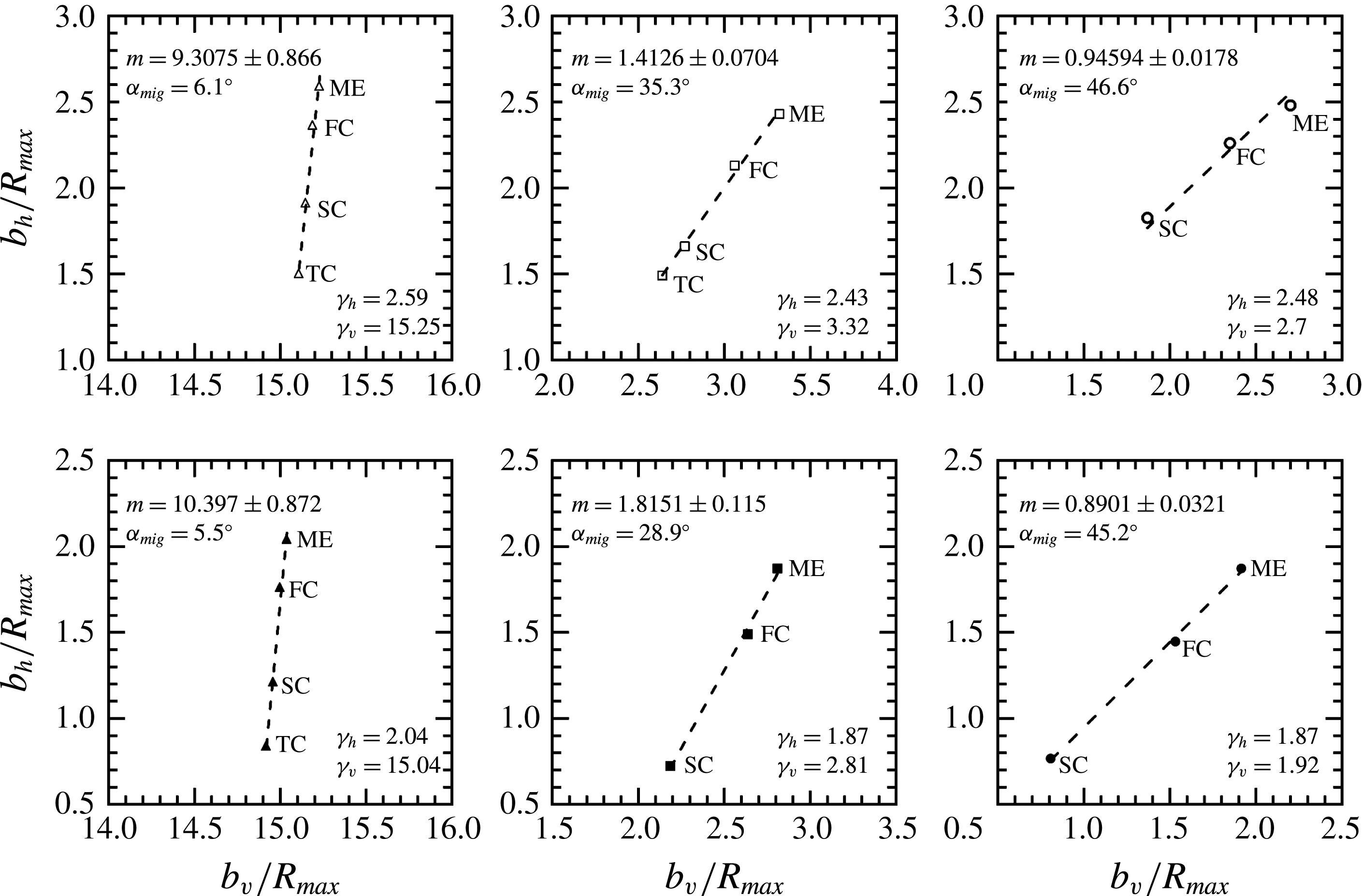
Not only the cavitation bubbles that are generated in close proximity to the rigid walls may cause damage, but also the bubbles generated further away because of the migratory motion of the bubble during the collapse phase. Figure 9 shows the position of the bubble centroid at the maximum expansion and near its minimum volume during first, second and third collapse for the cases illustrated in figures 2 and 3. Here,
 $b_{h}$
denotes the distance between the bubble centroid and the horizontal wall, while
 $b_{v}$
indicates the distance between the bubble centroid and the vertical wall. The measured data were fitted with linear regression (dashed line) and the slope of the regression line is indicated by
 $m$
. The inclination of the regression line with respect to a vertical plane is indicated by
 $\unicode[STIX]{x1D6FC}_{mig}$
, and corresponds to the inclination of the migration direction. At a given
 $\unicode[STIX]{x1D6FE}_{h}$
value, the inclination angle
 $\unicode[STIX]{x1D6FC}_{mig}$
increases on decreasing the initial distance between bubble and vertical wall. For example, for the cases shown in figure 3, it amounts to
 $6.1^{\circ }$
, for
 $\unicode[STIX]{x1D6FE}_{h}=2.04$
and
 $\unicode[STIX]{x1D6FE}_{v}=15.04$
(figure 3
a), up to
 $46.6^{\circ }$
, for
 $\unicode[STIX]{x1D6FE}_{h}=1.87$
and
 $\unicode[STIX]{x1D6FE}_{v}=1.92$
(figure 3
c). We also note that the direction of bubble migration coincides with that of the jet (the phenomenon is more readily observable in the movie format of figure 3(b), see supplementary material, movie 8). For example, for
 $\unicode[STIX]{x1D6FE}_{h}=2.43$
and
 $\unicode[STIX]{x1D6FE}_{v}=3.32$
(figure 2
b),
 $\unicode[STIX]{x1D6FC}_{mig}=35.3^{\circ }$
and
 $\unicode[STIX]{x1D6FC}_{jet}=35^{\circ }$
, while the corresponding values for
 $\unicode[STIX]{x1D6FE}_{h}=$
1.87 and
 $\unicode[STIX]{x1D6FE}_{v}=2.81$
(figure 3
b) are
 $\unicode[STIX]{x1D6FC}_{mig}=28.9^{\circ }$
and
 $\unicode[STIX]{x1D6FC}_{jet}=31^{\circ }$
.
Migratory behaviour of a bubble oscillating near two perpendicular rigid walls. Here
 $b_{h}$
is the distance between the bubble centroid and the horizontal wall, while
 $b_{v}$
is the distance between the bubble centroid and the vertical wall. ME indicates the position of the bubble centre at the maximum expansion, FC the position of the bubble centre at its minimum size during first collapse, SC the position of the bubble centre at its minimum size during second collapse, and TC the position of the bubble centre at its minimum size during third collapse. Finally,
 $m$
is the slope of a linear fit of the data (dashed line) and
 $\unicode[STIX]{x1D6FC}_{mig}$
is the inclination angle of the bubble migration with respect to a vertical plane.

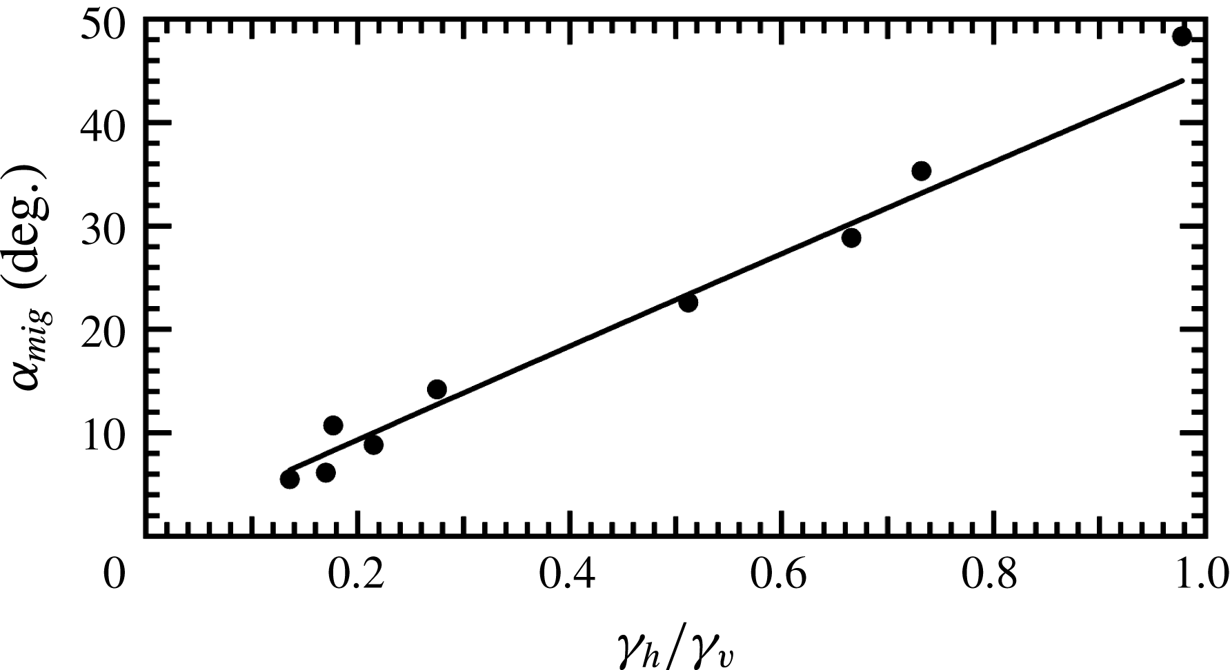
Figure 10 shows the inclination of the bubble direction
 $\unicode[STIX]{x1D6FC}_{mig}$
as a function of
 $\unicode[STIX]{x1D6FE}_{h}/\unicode[STIX]{x1D6FE}_{v}$
. To determine
 $\unicode[STIX]{x1D6FC}_{mig}$
, only those photographic sequences were used where the bubble, at its minimum volume, is not in contact with the horizontal wall near both first and second collapse. This way, the analyses were restricted to
 $\unicode[STIX]{x1D6FE}_{h}$
values larger than 1.8. The scaling law for the inclination angle
 $\unicode[STIX]{x1D6FC}_{mig}$
is the same as that for
 $\unicode[STIX]{x1D6FC}_{jet}$
, namely, the inclination angle of the bubble migration varies linearly with
 $\unicode[STIX]{x1D6FE}_{h}/\unicode[STIX]{x1D6FE}_{v}$
.
Inclination angle of the bubble migration with respect to a vertical plane,
 $\unicode[STIX]{x1D6FC}_{mig}$
, as a function of
 $\unicode[STIX]{x1D6FE}_{h}/\unicode[STIX]{x1D6FE}_{v}$
. The scaling law between the two parameters is
 $\unicode[STIX]{x1D6FC}_{mig}\propto \unicode[STIX]{x1D6FE}_{h}/\unicode[STIX]{x1D6FE}_{v}$
.

4 Discussion
4.1 Jet formation
When a bubble oscillates near a single, horizontal rigid wall, it is exposed to a unidirectional pressure gradient directed towards the wall. The pressure gradient is induced by the high pressure from a stagnation point situated near the bubble surface most distant from the rigid wall and by the low-pressure region between the bubble and rigid wall that develops during bubble collapse (Blake et al. Reference Blake, Taib and Doherty1987; Hsiao et al. Reference Hsiao, Jayaprakash, Kapahi, Choi and Chahine2014; Li et al. Reference Li, Han, Zhang and Wang2016). The bubble surface exposed to a higher pressure (i.e. the bubble surface situated farthest from the rigid wall) collapses faster, leading to the formation of a symmetric liquid jet in the direction of the pressure gradient (Blake et al. Reference Blake, Taib and Doherty1986; Tomita & Shima Reference Tomita and Shima1986; Vogel et al. Reference Vogel, Lauterborn and Timm1989; Philipp & Lauterborn Reference Philipp and Lauterborn1998). The closer the bubble is to the rigid wall, the larger is the strength of the pressure gradient acting on the bubble surface (Best & Blake Reference Best and Blake1994).
In addition to the pressure gradient generated by the horizontal rigid wall, a bubble situated near two perpendicular rigid walls is subjected to a second pressure gradient that is directed towards the vertical rigid wall. This case is particularly interesting because the perpendicular pressure gradients acting on the bubble motion lead to the formation of an inclined jet during bubble collapse. Other examples of inclined jet formation during the collapse of a bubble oscillating in perpendicular pressure gradients are the case of a buoyant bubble near a vertical rigid wall (the pressure gradient induced by the buoyant force is perpendicular to the pressure gradient directed towards the rigid wall) (Wang Reference Wang1998, Reference Wang2004; Zhang et al. Reference Zhang, Yeo, Khoo and Wang2001), a buoyant bubble below a free surface and near a vertical rigid wall (the pressure gradient induced by the high-pressure region developing between bubble and free surface during bubble growth is perpendicular to the pressure gradient directed towards the rigid wall) (Liu et al. Reference Liu, Wang, Wang and Zhang2016), and a bubble near a rigid wall subjected to ultrasound propagating parallel to the wall (the pressure gradient due to ultrasound is perpendicular to the pressure gradient induced by the rigid wall) (Wang & Manmi Reference Wang and Manmi2014; Wang et al. Reference Wang, Manmi and Calvisi2015). The inclination of the jet depends on the relative strength of the pressure gradients acting on the bubble surface. When the strength of one pressure gradient is much smaller than the other, the jet is only slightly inclined with respect to the direction of the dominant pressure gradient. When the pressure gradients are equally strong, corresponding to the case of a bubble generated at equal distances from the walls, the jet is directed in the bisection of the two pressure gradients.
When
 $\unicode[STIX]{x1D6FE}_{v}\gg \unicode[STIX]{x1D6FE}_{h}$
, the jet is only slightly inclined towards the vertical wall because the strength of the pressure directed towards the vertical wall is small compared to that directed towards the horizontal wall. The bubble migrates mainly towards the horizontal wall and the plane of the toroidal ring, formed after the jet penetrates the opposite bubble surface, is almost parallel to the horizontal wall. With decreasing
 $\unicode[STIX]{x1D6FE}_{v}$
, the strength of the pressure gradient directed towards the vertical wall increases and so does the jet inclination. For
 $\unicode[STIX]{x1D6FE}_{v}=\unicode[STIX]{x1D6FE}_{h}$
, the jet is inclined at
 $45^{\circ }$
and the toroidal bubble ring moves towards the corner made by the two rigid walls. For all (
 $\unicode[STIX]{x1D6FE}_{h},\unicode[STIX]{x1D6FE}_{v}$
) values investigated, the jet direction is the same as that of the bubble migration. Interestingly, the present results clearly show that, during the rebound phase of the bubble, both the inclination and the shape of the conical protrusion that contains the jet remain almost constant in time, at least in the parameter space (
 $\unicode[STIX]{x1D6FE}_{h},\unicode[STIX]{x1D6FE}_{v}$
) investigated here. This indicates that, once it has penetrated the opposite bubble surface, the jet flow is roughly symmetric.
Unfortunately, there are no experimental or numerical results on the dynamics of cavitation bubbles oscillating near two perpendicular rigid walls in order to make a direct comparison with the present results. Most of the previous numerical investigations have focused on the motion of a buoyant bubble situated near a vertical rigid wall. The numerical results of Wang (Reference Wang1998, Reference Wang2004) indicate that the jet is asymmetric in the initial stage of its propagation, changing both shape and inclination during its motion inside the bubble. However, the calculations were not extended to multiple connected domains and thus the jet flow through the opposite bubble surface was not examined. More recently, Zhang & Liu (Reference Zhang and Liu2015) investigated the motion of a buoyant bubble near a vertical rigid wall using an improved 3D BEM model that is able to simulate the jet motion after its penetration into the opposite bubble surface. Their results show that the jet flow is nearly symmetric and, although its direction changes with time, the jet inclination tends to stabilize at a certain angle (as indicated by the last two frames of their figures 16 and 17). We note, however, that they simulated the oscillation of a bubble situated very close to the rigid wall (the stand-off parameter in their simulation is smaller than one), and covers only the very initial period of the bubble rebound (the time interval investigated is less than 1.03 times the oscillation period of the bubble). In the present investigations, the jet inclination was determined for bubbles situated at
 $\unicode[STIX]{x1D6FE}_{h}$
values larger than 1.5, in a much later stage of the rebound phase.
4.2 Toroidal bubble collapse
The most interesting behaviour of the torus ring was found when the distance between the initial location of the bubble and the horizontal rigid wall equals the maximum bubble radius. The inclined jet leads to the formation of an asymmetric torus ring that collapses in both radial and toroidal directions, starting from the torus part opposite to the vertical rigid wall. The closer the bubble is to the vertical rigid wall, the more inclined is the liquid jet formed during bubble collapse, and the earlier is the occurrence of the collapse in the toroidal direction in the second oscillation period of the bubble. Eventually, the toroidal bubble achieves a crescent shape that migrates strongly towards the vertical rigid wall. We also note that the inclination of the torus plane increases with decreasing distance between the bubble and the vertical wall (figure 4). When the bubble is situated at equal distances from the perpendicular walls, the torus plane is inclined at
 $45^{\circ }$
and the torus collapses only in the radial direction. The formation of an asymmetric toroidal bubble shape was also observed at large
 $\unicode[STIX]{x1D6FE}_{h}$
values. However, during rebound and following oscillation cycles, the torus oscillates only in the radial direction, as can be seen in figures 2 and 3.
An asymmetric torus formation was also observed by Liu et al. (Reference Liu, Wang, Wang and Zhang2016) in the numerical simulations of the interaction of a bubble situated near a vertical rigid wall with a free surface. They investigated, however, only the collapse phase of the bubble, and no details on the torus dynamics during its rebound were provided. The pinch-off of an asymmetric toroidal bubble was observed by Li et al. (Reference Li, Kripfgans, Fabiili, Fowlkes and Bull2014) for the case of a bubble attached to a rigid wall and subjected to ultrasound that makes an angle of
 $25^{\circ }$
with respect to the rigid wall. Since no pronounced collapse of the bubble and no jetting were observed, they suggested that the pinch-off may be a consequence of the acoustic radiation force. We have no clear evidence of the cause of the faster collapse of the torus part situated farthest from the vertical wall. It may be a consequence of an asymmetric distribution of the vorticity around the circumference of the torus ring, generated by the oblique impact of the jet onto the horizontal rigid wall, with a maximum around the torus part closer to the vertical rigid wall and a minimum around the opposite torus part. Moreover, since the torus ring is inclined with respect to the horizontal wall (figure 4
b, frame 21), the vorticity around the torus part situated farthest from the vertical wall is further diminished by the viscous boundary layer near the horizontal wall.
Chahine & Genoux (Reference Chahine and Genoux1983) have showed that the collapse of a circular vortex ring becomes faster with decreasing circulation around it. This may also apply locally for different parts of a toroidal vortex ring with a non-uniform distribution of vorticity around it. Thus, the torus part most distant from the vertical wall collapses faster than the torus part closest to the vertical wall. This may also explain the initial faster rebound of this torus part indicated in figure 6. At
 $\unicode[STIX]{x1D6FE}_{v}=\unicode[STIX]{x1D6FE}_{h}$
, the bubble achieves a disc-like shape in the final stage of the collapse, which is inclined at
 $45^{\circ }$
, and the jet impacts the corner made by the two rigid walls in a late stage of bubble rebound. The impact velocity of the jet onto the corner is too small to generate a strong rotational flow around the resulting torus ring. When the bubble is generated far from the rigid walls, the vortex ring is formed during the final stage of the second oscillation period of the bubble (figures 2 and 3), where the bubble motion is more symmetric. The vorticity has an almost uniform distribution around the torus circumference and the torus ring collapses only in the radial direction. Much higher framing rates than those used in the present investigations, combined with 3D numerical simulations that are able to portray not only the temporal development of the bubble shape but also the evolution of the pressure field and velocity vectors in the fluid surrounding the bubble, must be used in order to gain a better understanding of the complex dynamics.
5 Conclusions
The behaviour of a laser-induced cavitation bubble near two perpendicular rigid walls, and its dependence on the distance between bubble and walls, was investigated by high-speed photography with
 $100\,000~\text{frames}~\text{s}^{-1}$
.
An inclined liquid jet is formed during bubble collapse and the bubble migrates in the direction of the jet. When the bubble is generated at equal distances from the rigid walls, the jet is directed in their bisection. The inclination angle of the jet scales with the ratio of the distances between the initial location of the bubble and rigid walls,
 $\unicode[STIX]{x1D6FE}_{h}/\unicode[STIX]{x1D6FE}_{v}$
. The penetration of the inclined jet into the opposite bubble wall leads to the formation of an asymmetric toroidal bubble. When the bubble is situated at large distance from the rigid walls, the torus plane is perpendicular to the direction of the jet and the toroidal bubble collapses only in the radial direction, eventually, disintegrating into microbubbles.
When the bubble is in contact with the horizontal wall at its maximum expansion, the toroidal bubble ring collapses in both radial and toroidal directions, starting from the torus part opposite to the vertical wall, and the bubble achieves a crescent shape at the moment of second collapse. A strong migration of the bubble along the horizontal rigid wall was observed in this case. The closer the bubble is to the vertical rigid wall, the more inclined is the liquid jet formed during bubble collapse, and the earlier is the occurrence of the collapse in the toroidal direction in the second oscillation period of the bubble. When the bubble is situated at equal distances from the perpendicular walls, the torus plane is inclined at
 $45^{\circ }$
, and the torus collapses only in the radial direction.
Acknowledgements
This work was supported by a grant of the Japan Society for the Promotion of Science, grant S-12169, and by the Romanian National Authority for Scientific Research, CNCS–UEFISCDI, project number PN-II-ID-PCE-2011-3-0079.
Supplementary movies
Supplementary movies are available at https://doi.org/10.1017/jfm.2018.82.