I. INTRODUCTION
Electrospinning has been widely used to produce nanofibers,Reference Greiner and Wendorff1, Reference Li and Xia2 and electrospun nanofibers have shown potential in different applications.Reference Ramakrishna, Fujihara, Teo, Lim and Ma3 However, the extremely low production rate, usually less than 0.1 g/h,Reference Varabhas, Chase and Reneker4 limits further application and commercialization of nanofibers. Efforts have been made to increase the production rate of nanofibers in electrospinning by using multiple needles/channels.Reference Tomaszewski and Szadkowski5–Reference Zhou, Gong and Porat8 However, strong charge repulsion between neighboring polymer jets and clogging of the needles/channels affects either the spinning process or the quality of the as-spun nanofibers. Needleless electrospinning has been reported to increase the productivity of nanofibers.Reference Yarin and Zussman9–Reference Lu, Wang, Liu, Duan, Zhou, Wang, Li, Wang, Lan and Xie11 It shows great potential in enhancing the productivity of nanofibers as numerous polymer jets were generated at the same time and uniform nanofibers were produced.
The generation of multiple jets in needleless electrospinning can be attributed to electrically amplified liquid waves.Reference Lukas, Sarkar and Pokorny12 Jet formation in needleless electrospinning is thus highly influenced by the external electric field intensity. Efforts have been focused on the modeling of electrospinning so as to understand the electric field together with the spinning process.Reference Krucinska, Komisarczyk, Chrzanowski, Gliscinska and Wrzosek13–Reference Carrol and Joo16 However, most researchers paid attention to the needle-based electrospinning setup. For a three-dimensional (3D) needleless electrospinning setup, the geometry of the spinneret greatly influences the distribution of the electric field intensity profile thus affecting the electrospinning process and fiber properties. The finite element method (FEM) has been used to analyze the electric field profile in electrospinning.17 Since the practical dimensions and material properties can be used for the FEM calculation, it enables us to visualize the electric field intensity profile and to understand how this profile may be influenced by spinneret geometry as well as material characteristics.
Spinnerets with various geometries in needleless electrospinning system, such as cylinder,Reference Jirsak, Sanetrnik, Lukas, Kotek, Martinova and Chaloupek18 disk/multiple disks,Reference Niu, Lin and Wang19 ring/multiple rings/coil,Reference Wang, Niu, Wang and Lin20 have been used to produce nanofibers. Those spinnerets show fairly different electric field profiles under the same applied voltage; it is worthwhile to investigate the influence of spinneret shape on the electric field so as to determine the optimized spinneret. In this study, the electric field profile of spinnerets in needleless electrospinning was modeled using the 3D finite element analysis software COMSOL Multiphysics 3.5a. The electric field intensity was then calculated from the profiles for comparison. This study benefits the design and development of needleless electrospinning in which the spinneret is a crucial factor affecting the quality of the as-spun nanofiber and productivity.
II. MODELING
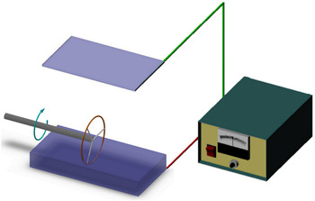
A typical needleless electrospinning process is illustrated in Fig. 1. A ring is applied as sample spinneret, and a polymer bath in which the ring is partly immersed is used to provide polymer solution to the spinneret. A plate is used as the collector of nanofibers when high voltage is supplied by the power supply between the spinneret and the collector. To ease the understanding, distance along the axial direction refers to the distance along the shaft (in the center of the ring) and distance along the spinning process refers to the distance from the top of the spinneret to the collector.
Schematics of needleless electrospinning.

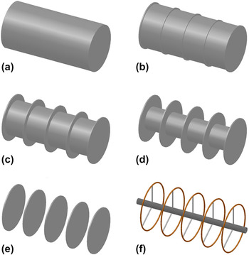
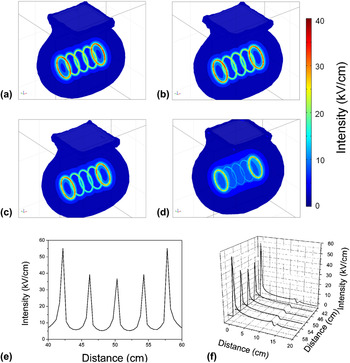
Different spinnerets were first defined using SOLIDWORKS (as shown in Fig. 2). A bi-interface was used to transfer the defined geometry into the COMSOL interface, and other parts such as plate collector (24-cm long, 15-cm wide, and 5-mm thick) and bath (24 cm in length, 10 cm in width, and 4 cm in height) could then be drawn directly in COMSOL Multiphysics. After setting the subdomain and boundary, the meshing process could be performed and the electric field intensity profile could be solved as shown in Fig. 3. A cross-sectional line could be drawn arbitrarily to show the electric field intensity along that line. Most specifically, cross-sectional line could be set through the surface of the spinneret at the axial direction and from the spinneret to the collector at the spinning direction. The results showed the electric field intensity distribution of the setup at the axial direction [Fig. 3(e)] and along the spinning direction [Fig. 3(f)], respectively.
Schematics of different spinnerets for needleless electrospinning: (a) cylinder (length = 16 cm, diameter = 8 cm); (b–e) multiple disks (thickness = 2 mm, diameter = 8 cm, spacing = 4 cm) linked with a shaft with a radius of 38, 30, 20, and 0 mm, respectively; (f) multiple rings (wire diameter = 2 mm, diameter = 8 cm, spacing = 4 cm) linked with a shaft with a radius of 5 mm.

Electric field profiles of multiple disks linked with a shaft with different shaft radius: (a) 0 mm, (b) 20 mm, (c) 30 mm, and (d) 38 mm. And electric field intensity of multiple disks (shaft radius 0 mm) along the axial direction (e) and spinning direction (f). (Applied voltage 60 kV, collecting distance 13 cm.)

III. RESULTS AND DISCUSSION
A. Evolution from cylinder to disk
Based on a cylinder spinneret, an array of disks with a shaft can be evolved as the radius of the shaft decreases. Schematics of multiple disks linked with a shaft are shown in Figs. 2(b)–2(e). The radius of the shaft is in the range of 0–40 mm. The interdisk distance is between 0 and 40 mm.
1. Effect of shaft radius
Figure 3 shows the electric field profiles of multiple disks with different shaft radius. A strong electric field is formed on both ends of the spinnerets. The strong electric field can also be found on the top of each disk when no shaft (radius = 0, multiple disks) is used, as shown in Fig. 3(a). With the increase of the shaft radius, the electric field intensity on the disk surface become weaker. When the shaft radius increases to 38 mm, the electric field intensity of the middle disks is almost the same as that of the shaft surface. At this stage, the spinneret looks more like a cylinder rather than multiple disks as shown in Fig. 3(d). Figures 3(e) and 3(f) show a typical electric field intensity distribution along the axial and spinning direction. Very strong electric field intensity is formed on the top of each disk, and the intensity drops suddenly along the spinning direction.
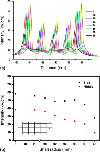
Electric field intensity of multiple disks on a shaft with different shaft radius is shown in Fig. 4(a). For cylinder (shaft radius 40 mm), there are no intensity peaks formed in the middle area. With the decrease in the shaft radius, peaks appear on the top of each disk become more evident. As the shaft radius decreases from 40 to 30 mm, the electric field intensity increases evidently. It is evident that the decrease of the radius of the shaft causes the disks to protrude from the surface of the shaft; electric charges will be distributed on the surface of disk edges of which the curvature is very high, thus high electric field will be concentrated on these areas.
Electric field intensity of multiple disks linked with a shaft with different shaft radii: (a) axial direction, (b) comparison of the intensity peaks (inset: schematic view of the radius of the shaft). (Applied voltage 60 kV, collecting distance 13 cm.)

Figure 4(b) shows the electric field intensity of both the middle and side disks at different shaft radius. The intensity decreases gradually with the increase of the shaft radius, and it drops to a very low level when the shaft radius approaches 40 mm, under which the spinneret behaves more like a cylinder with an uneven surface. It is evident that evolution from cylinder to multiple disks could concentrate electric field more efficiently.
2. Effect of disk spacing
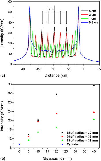
A cylinder can be regarded as multiple disks with interdisk spacing of zero, thus the disk spacing greatly influences the electric field of multiple disk spinneret. Figure 5 shows the electric field intensity of spinnerets with different disk spacing. When the distance is too short, 0.5 cm for instance, two peaks emerge at the top of the disk at both ends and no evident electric field intensity peaks can be formed on the top of other disks; the intensity of the disk in the middle areas fluctuates around 15 kV/cm. The whole trend of the intensity curve in this case is similar to that of cylinder as shown in Fig. 4(a), suggesting that multiple disks with very short disk spacing behave like a cylinder in needleless electrospinning. Many peaks are observed when the disk spacing increases to 1 cm, but the intensity of the peaks is still very low. With the further increase of the disk spacing, the number of the peaks in the middle area decreases due to the reduction of the number of disks. However, the intensity of the individual peaks increases clearly.
Electric field intensity of multiple disks linked with a shaft under different disk spacing: (a) axial direction (shaft radius 30 mm, inset: schematic view of disk spacing); (b) comparison of the intensity peaks of the middle disk under different shaft radii. (Applied voltage 60 kV, collecting distance 13 cm.)

Figure 5(b) shows the electric field intensity of the middle disk with different disk spacing under different shaft radii. It is observed that with an increase of disk spacing from 0 to 20 mm, the intensity increases. Furthermore, an increase of the disk spacing from 20 to 40 mm leads to a slight increase of the intensity. The smaller the shaft radius, the stronger the intensity as discussed before. When the disk spacing is too close, the whole spinneret behaves more like a cylinder with an uneven surface, thus the intensity approaches that of the middle of a cylinder, as shown in Fig. 5(b). Increasing the disk spacing to 40 mm can greatly increase the electric field intensity of each disk. As the disk spacing decreases, more disks might be able to be used to generate needleless electrospinning and the fiber productivity can be increased accordingly. However, the electric field intensity of each disk must be high enough to trigger needleless electrospinning.
It is obvious that at lower disk spacing, the spinneret behaves like a cylinder with uneven surface. Conversely, increase of disk spacing will make each disk more isolated from each other, and highly concentrated electric fields will be formed on the top of each disk.
B. Evolution from disks to rings
Evolution from cylinder to disks could be regarded as the optimization of the cylinder spinneret at its axial direction. Optimization of the cylinder spinneret at its radial direction could then result in the evolution of multiple disks into multiple rings/coil.
1. Comparison between multiple disks and multiple rings
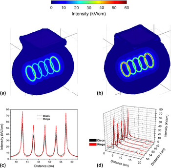
Figure 6 compares the electric field profile and the electric field intensity of multiple disks and multiple rings under the same conditions. The electric field profile shows that stronger electric field is formed on the top of each ring with stronger intensity compared to the specific disk, as shown in Figs. 6(a) and 6(b). The electric field intensity of multiple rings is much higher than that of multiple disks, from Figs. 6(c) and 6(d), thus multiple rings generate stronger electric field than multiple disks.
Electric field comparison of multiple disks and multiple rings: (a–b) electric field profiles of multiple disks and multiple rings, respectively; (c–d) electric field intensity along the axial and spinning direction, respectively. (Applied voltage 60 kV, collecting distance 13 cm, disk/ring distance 4 cm.)

Changing from disk to ring could make the edge of the spinneret into sharp curvature, and thus, electric charges will be concentrated to form stronger electric field. It could be estimated that more polymer jets will be produced under stronger electric field due to higher electrostatic forces exerted on the polymer solution; the productivity would then be enhanced greatly. Besides, thinner and more uniform nanofibers may be produced due to the stronger electric field.
2. Effect of the number of rings
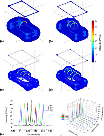
Electric field profiles of the spinnerets with different numbers of rings are shown in Fig. 7. Strong electric field is formed on the top half area of each ring with intensity higher than 50 kV/cm. When the number of rings increases, it is evident that stronger electric field tends to form on the side rings. When a shaft is used to connect the multiple rings, the influences of shaft radius and interring distance show similar trends as those of the multiple disks described previously.
Electric field of ring/multiple ring spinnerets with different number of rings: (a–d) electric field profiles; (e–f) electric field intensity along the axial and spinning direction, respectively. (Applied voltage 60 kV, collecting distance 13 cm, ring distance 4 cm.)

Figures 7(e) and 7(f) show the electric field intensity of the rings. High electric field intensity is distributed on the top of each ring, and the intensity drops quickly along the spinning way. It shows that higher electric field intensity distributes on the side rings and intensity of the middle rings decreases slightly when the ring number increases. Further increase of the number of rings will make the intensity peaks of the rings in the middle areas decrease to too low level to generate polymer jets. A proper number of rings can be decided based on the electric field analysis together with the minimum electric field intensity that could trigger needleless electrospinning process in experiments.
C. Design of spinneret
Previous study on needleless electrospinningReference Niu, Lin and Wang19, Reference Wang, Niu, Wang and Lin20 has proven that electric field of spinneret influences the diameter and productivity of as-spun nanofibers. Spinneret with concentrated electric fields produced thinner and more uniform nanofibers with relatively higher productivity due to stronger electrostatic forces.Reference Wang, Niu, Wang and Lin20 Electric field analysis must be taken into consideration when designing the spinneret for needleless electrospinning. Electric field profile together with electric field intensity of the spinneret will be the most important factors to determine the geometry of the spinneret. The most prominent spinneret of needleless electrospinning would be the spinneret that concentrates the strongest electric field in the largest areas of itself.
IV. CONCLUSIONS
Electric field profile together with electric field intensity can be simulated and analyzed using FEM method on software COMSOL Multiphysics. The electric field profile of a cylinder shows concentrated electric fields at both ends of the cylinder, while multiple disks show higher concentrated electric fields on the top of each disk, and the intensity increases when the shaft radius decreases and the disk spacing increases. Multiple rings show stronger electric field profile and intensity than that of multiple disks under the same experimental conditions. Increasing the number of rings results in a decline in the electric field intensity of the middle rings. Evolution of the spinneret of needleless electrospinning from cylinder to multiple disks and then to multiple rings results in stronger and more concentrated electric fields. The most prominent spinneret of needleless electrospinning would be the spinneret that concentrates the strongest electric field in the largest areas of itself. The analysis based on 3D simulation of the electric field could benefit further development of needleless electrospinning in which the production rate and quality of as-spun nanofibers are of great importance.
ACKNOWLEDGMENTS
Funding supports from National Natural Science Foundation of China (Grant No. 51103109) and Education Bureau of Hubei Province, China (Grant No. D20121710), are greatly appreciated.