I. INTRODUCTION
TiAl-based alloys are the promising candidate to replace the widely used Ni-based superalloys partly at 600–800 °C, Reference Ding, Lin, Zhang, Su, Wang and Chen1–Reference Tian, Wang, Yu, Sun and Li3 the service temperature can be much higher by proper alloying or post treatment. Reference Weidner, Pyczak and Biermann4,Reference Yang, Tane, Lin, Song and Nakajima5 However, due to high melting point and high activity, its preparation is generally very difficult. After years of efforts, different kinds of processing methods are applied successfully. Reference Kabir, Bartsch, Chernova, Kelm and Wischek6,Reference Ding, Chen, Guo, Bi, Xu and Fu7 For metal materials, casting is always one of the most direct and effective processing methods. Compared with thermo–mechanical treatment, Reference Niu, Chen, Xiao and Xu8–Reference Niu, Chen, Xiao, Kong and Zhang10 no deformation structure is brought by casting, which is benefit for creep resistance and endurance property at high temperature. Furthermore, contamination and defect in the cast can be well-controlled nowadays and the cost is lower. Cold crucible directional solidification (CCDS) Reference Dong, Chen, Guo, Ding, Su and Fu11,Reference Yang, Chen, Ding, Guo, Han and Fu12 is an effective technique to prepare TiAl-based alloy ingots with industry size, directionally solidified (DS) macrostructure and better axial mechanical properties, but without contamination.
According to the service condition, alloying is an effective method to improve a certain property by adding specific elements, and nowadays “lower Al content and higher β-stabilizers” is the main development tendency. Chen Reference Ding, Lin, Zhang, Su and Chen13,Reference Ding, Lin, Zhang, Song and Chen14 has proposed “High-Nb TiAl-based alloys,” because of their higher service temperature, better mechanical properties and excellent deformation processing capacity, more and more attention has been attracted. However, a tough problem that lots of B2 phase in this kind of alloy induced by more addition of Nb has always not been well-treated. As well known, B2 phase is a kind of hard phase at room temperature (RT), but the soft phase at high temperature, and too much B2 phase will be harmful for the mechanical properties. Reference Song, Zhang, Xu, Sun and Lin15 Heat treatment (HT) is an effective method to solve this problem. Appropriate HT can eliminate, reduce or disperse B2 phase, and then improve the properties. Certainly, HT can also be used to refine the colonies. Peng Reference Peng, Huang and Tang16 reported that cyclic heat treatment (CHT) could refine the colonies obviously and Wang Reference Yang, Wang, Xia and Wang17,Reference Xia, Wang, Wang and Yang18 revealed the refining mechanism of CHT on TiAl alloys. Firstly, γm phase should be acquired by quenching as the starting microstructure, since there are many nucleation sites in this phase. Secondly, higher heating and cooling rate is needed. The refining is mainly induced by γm → α′, in which α′ can precipitate from four habit planes of γm according to the (0001)α′//(111)γm, as a result, a larger γm grain can be divided into four smaller α grains. Finally, through 3–5 times of cycles, the microstructure will be composed of refined colonies. However, CHT brings about three problems: one is that much γm phase is necessary for starting microstructure, therefore it is infeasible for lower Al content alloys; two is that the higher heating and cooling rate can lead to more defects that is harmful for the properties; three is that, even if the refine-grain alloys with no or less defects (by hot isostatic pressing) can be acquired, the better creep resistance and endurance property are also not expected.
In this paper, two kinds of high-Nb contained TiAl-based alloys are prepared, and then DS. The cast and DS ingots are heat treated by different schedules, the microstructure evolution is investigated and mechanical properties are tested. The mechanism of effect of HT on the microstructure and properties is discussed, and the optimized HT schedules are proposed.
II. EXPERIMENTAL DETAILS
A. Ingots preparation
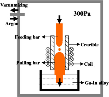
Two β-type TiAl-based alloys, Ti44Al6Nb1.0Cr2.0V (at.%, in short as A1) and Ti44Al6Nb1.0Cr2.0V0.1B0.15Y (at.%, in short as A2) are designed, and they are prepared by two casting methods, vacuum consumable melting (VCM) and CCDS. During VCM, the alloys are melted two times for homogenization, and the ingot size is around Ø225 mm × 320 mm. The previous research Reference Dong, Chen, Guo, Ding, Su and Fu19 shows that the composition of the two ingots is homogeneous. The two alloys are DS by CCDS method, which is described in detail in Ref. Reference Yang, Chen, Ding, Guo, Han and Fu20 and the experimental schematic is shown in Fig. 1.
Schematic of CCDS experimental course.

B. Heat treatment
To explore the HT schedule, the samples with smaller size (10 mm × 10 mm×10 mm) are heat preservation at 1100, 1150, 1200, 1250, 1260, 1270, 1280, 1290, 1300, 1310, 1320, and 1350 °C for 180 min respectively, and then water quenched (WQ). It finds that 1100–1280 °C is located in (B2 + α2 + γ) phase region and 1290–1350 °C is located in (B2 + α) phase region. Finally, several tentative HT schedules are given in detail according to the experimental results above (see Fig. 5 and Table I , being discussed in detail later). To prevent oxidation of TiAl alloys at high temperature, the samples are coated by oxidation-resistant coating and then sealed in the thermoduric quartz tube with high-purity argon gas in it.
HT schedule in detail and the applicative alloy.

C. Microstructure investigation
X-ray diffraction (XRD) is used to conduct the phase analysis with Cu target Kα radiation (λ = 0.154157) and 2θ is from 20° to 90°. Scanning electron microscopy (SEM) in back-scattered electron mode and transmission electron microscopy (TEM) are used to investigate the microstructure. TEM samples are prepared as following: firstly, cut down the 300 μm foils, secondly, grind to the thickness 80–90 μm, finally, jet electro-polish in the solution composed of 60% (vol%) methanol, 32% butyl alcohol and 8% perchloric acid at 30 V and −30 °C for about 45–50 s that the power can be automatically cut instantly when a center hole appeared.
D. Mechanical property
The specimens are tensile tested at RT on 5669-type Instron testing machine (Instron, Shanghai, China) with pulling rate of 0.5 mm/min. The gauge size is 18 mm × 6 mm × 2 mm. At least 5 valid samples are tested for each condition.
III. RESULTS AND DISCUSSION
A. HT schedule exploration
There are always some controversies about the influence of B2 phase on mechanical properties, Reference Song, Zhang, Xu, Sun and Lin15 however it is sure that too much B2 phase and its heterogeneous distribution must be harmful. Thus, a straightforward aim of HT is to reduce B2 phase and homogenize its distribution. Besides that, for CCDS ingots, the columnar grains and the small angle lamellas Reference Dong, Chen, Guo, Ding, Su and Fu11 should be reserved after HT, which will make it more difficult and complex.
The heavy-alloying A1 and A2 contain five and seven kinds of elements, respectively, and correspondingly, the quinary and septenary phase diagram should be referred to for establishing HT schedule. However, it is hard work to establish the multiple phase diagrams, therefore two simplified steps are conducted: firstly, it is deemed that the two alloys have the same solidification route, since only slight B and Y are added that their effect on phase region can be neglected; secondly, because Nb, Cr, and V are all β-stabilizers with the similar role, it does no harm to compute them as “Nb equivalent,” and then take the existed Ti–Al–Nb ternary phase diagram as the reference. Sun et al. Reference Sun, Cao, Kim, Lee and Yan21 has proposed an empirical equation of Cr equivalent as follows:
 $$[{\rm{Cr}}] = {\rm{Cr}} + {\rm{Mn}} + {3 \mathord{\left/ {\vphantom {3 5}} \right. \kern-\nulldelimiterspace} 5}{\rm{V}} + {3 \mathord{\left/ {\vphantom {3 8}} \right. \kern-\nulldelimiterspace} 8}{\rm{Nb}} + {3 \mathord{\left/ {\vphantom {3 2}} \right. \kern-\nulldelimiterspace} 2}\left( {{\rm{W}} + {\rm{Mo}}} \right) + 3{\rm{Fe}}\quad .$$
Equation (1) can be changed as Eq. (2) when Nb equivalent is taken:
 $$[{\rm{Nb}}] = {\rm{Nb}} + {8 \mathord{\left/ {\vphantom {8 3}} \right. \kern-\nulldelimiterspace} 3}({\rm{Cr}} + {\rm{Mn}}) + {8 \mathord{\left/ {\vphantom {8 5}} \right. \kern-\nulldelimiterspace} 5}{\rm{V}} + 4\left( {{\rm{W}} + {\rm{Mo}}} \right) + 8{\rm{Fe}}\quad {\rm{.}}$$
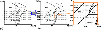
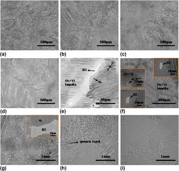
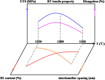
According to Eq. (2), it can be deduced that the equivalent Nb content is about 11% for the two alloys. Zhong et al. Reference Zhong, Yang, Li, Wang, Zhang, Li and Zhang22 has reported that the Ti–Al–10Nb phase diagram as shown in Fig. 2(a). Comparing with the Ti–Al–6Nb Reference Zhong, Yang, Li, Wang, Zhang, Li and Zhang22 and Ti–Al–8Nb Reference Zhong, Yang, Li, Wang, Zhang, Li and Zhang22 phase diagrams, the main differences manifest in the follows: β and (B2 + α) phase regions move right; α phase region gets smaller; (B2 + α + γ) phase region is stable to RT; the closing point of α phase region is obviously right-moved and converting into an intersection of four phase regions. The Ti–Al–10Nb phase diagram can be taken as reference for our “equivalent Ti–Al–11Nb alloy,” however, two problems should be noticed: firstly, the “equivalent 11Nb” is acquired by empirical formula that there may be deviation with the actual situation; secondly, the specific corresponding relationship among temperature, component and phase region are still uncertain. Therefore, WQ experiment is carried out on A1 alloy. Figure 3 lists some typical WQ microstructure under different temperatures. It finds that RT–1280 °C is located in (B2 + α2 + γ) phase region and 1290–1350 °C is located in (B2 + α) phase region. WQ results also indicate that the deduction above is feasible, and this Ti–Al–10Nb phase diagram is applicable for our alloys. Figure 2(b) exhibits the corrected phase diagram according to WQ results, and it finds that 1280 and 1290 °C locate in (B2 + α2 + γ) and (B2 + α) phase region, respectively, and they border on the transus. From the microstructure: when it is at the equilibrium state of 1280 °C, the (α2 + γ) lamella structure still exists and there is less B2 phase; when 1290 °C, similarly, less B2 phase exists, but the lamella structure has disappeared. Thus, this 1280–1290 °C is considered to be suitable for eliminating B2 phase. It should be noted that it is not the only temperature range that B2 phase can be eliminated effectively, but the effect may be better at higher temperature. However, the higher the temperature is, the larger the interlamellar spacing is and the more the microcrack may be induced, which are harmful to mechanical properties. Figure 4 is the schematic showing the relationship among HT temperature, B2 phase component, interlamellar spacing, and RT tensile property, which is obtained from our previous research. Reference Dong, Chen, Guo, Ding, Su and Fu19 Note that, B2 phase cannot be eliminated completely by annealing for the heavy-alloying TiAl-based alloys due to the more addition of β stabilizers.
Reference phase diagram and modified phase diagram: (a) Ti–Al–10Nb Reference Zhong, Yang, Li, Wang, Zhang, Li and Zhang22 reference phase diagram; (b) modified Ti–Al–11Nb phase diagram according to the WQ experimental results.

WQ microstructure under different temperatures: (a) 1100 °C; (b) 1150 °C; (c) 1200 °C; (d) 1250 °C; (e) 1250 °C at higher magnification; (f) 1280 °C; (g) 1290 °C; (h) 1320 °C; (i) 1350 °C.

Schematic relationship among HT temperature, B2 phase component, interlamellar spacing, and RT tensile property taking our previous research as reference.

B. HT for ingots by VCM
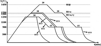
Five tentative HT (HT1–HT5) schedules are proposed and listed in Table I and are also presented in Fig. 5. From HT1 to HT5, the temperature increases gradually. To avoid the formation of microcrack and the enlargement of defects induced by thermal stress, the slower heating and cooling at higher temperature are used except HT1.
Schematic diagram of HT schedule.

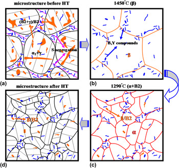
Specially, HT5 schedule is carried out only on A2 alloy. Slowly cooling from β phase region can further refine the casting microstructure of B-contained alloys that has been demonstrated by Oehring, Reference Oehring, Stark, Paul, Lippmann and Pyczak23 however, the related mechanical properties have not been given. Similarly, it can be deduced that there will be the similar refining function of Y. The refining mechanism can be described in Fig. 6 and the following heat preservation at 1290 °C is a newly designed and innovative step for reducing or dispersing B2 phase. Combining with this schematic, the refining mechanism by HT5 can be described as follows:
Schematic of HT5 mechanism on A2 alloy: (a) microstructure before HT; (b) microstructure of 1450 °C; (c) microstructure of 1290 °C; (d) microstructure after HT.

As shown in Fig. 6(a), the original microstructure is composed of most (α2 + γ) lamella structure and some (B2 + γ) blocky morphology, and certainly, the individual B2 phase and B, Y contained precipitations can also been observed. When B2 phase is at colony boundaries and triple junctions, β-segregation is presented and the lamellas around it often have the same orientation. Reference Oehring, Stark, Paul, Lippmann and Pyczak23 When B2 phase is within the lamellas, α-segregation is presented and the lamellas around it is often coarsened or slight curled that has been detected and explained by Ding. Reference Ding, Lin, Zhang, Song and Chen14 S-segregation Reference Xu, Lin, Teng, Wang and Chen24 (or called L-segregation that corresponding to residual liquid region) can occasionally been found, which implies the sequence characteristic of solidification. Due to the low solubility of B, most of them are excluded into the liquid (subsequent solidification region) during solidification, and as a result, there are relatively more stripe shaped TiB precipitation in these regions than that in lamella colonies. It seems that the distribution of Y contained precipitation is less affected by solidification course. The similar distribution behavior of B and Y precipitations has also been found in mushy zone of CCDS ingots in our previous experiment. Reference Chen, Dong, Guo, Ding, Su and Fu25
As shown in Fig. 6(b), when it is heat preservation at 1450 °C, the microstructure is composed of β phase and B, Y contained precipitations. The precipitations are not dissolved in β phase, because their formations are completed before T
β
Reference Gosslar, Günther, Hecht, Hartig and Bormann26
 $\left( {{\rm{L}} + \beta \buildrel {{T_\beta }} \over\longrightarrow \beta } \right)$
, e.g. the secondary TiB forms in the eutectic reaction L → β + TiB.
Reference Oehring, Stark, Paul, Lippmann and Pyczak23,Reference Gosslar, Günther, Hecht, Hartig and Bormann26
In fact, the rudiment of β grains can be seen from Fig. 3(i), which exhibits the similar morphology as Fig. 6(b), and the corresponding 1350 °C is close to β phase region, since more B2 phases are contained in the WQ microstructure.
As shown in Fig. 6(c), during β → α transformation, α phase nucleates heterogeneously at B, Y precipitations and a certain number of α phase orientations might occur with respect to the precipitation that will promote the heterogeneous nucleation of α phase: e.g. Oehring, Hill as well as Hu et al.
Reference Hu, Yang, Huang, Dixon and Hecht27,Reference Hu, Yang, Huang, Dixon and Hecht28
has found that TiB precipitation with B27 structure is precipitated from β phase in 12 possible orientations due to
 $\{ 011\} \beta //(001){\rm{B}}27$
and
 $\left\langle {111} \right\rangle \beta //[010]{\rm{B}}27$
, and then α can precipitate on TiB according to
 $(0001)\alpha //(001){\rm{B}}27$
and
 $\left\langle {11\bar 20} \right\rangle \alpha //[010]{\rm{B}}27$
. Besides that, the orientation relationship
 $[0\bar 111]\alpha //[\bar 104]{\rm{B}}27$
and
 $[2\bar 1\bar 10]\alpha //[010]{\rm{B}}27$
Reference Genc, Banerjee, Hill and Fraser29
as well as
 $(1\bar 101)\alpha //(001){\rm{B}}27$
,
 $(11\bar 20)\alpha //(010){\rm{B}}27$
,
Reference Banerjee, Genc, Hill, Collins and Fraser30
and
 $(1\bar 10\bar 2)\alpha //(100){\rm{B}}27$
have also been found in Ti-based alloys. Thus, a large number of α phase orientations are generated that can refine the final microstructure. The following heat preservation at 1290 °C can reduce B2 phase effectively, however, to prevent the excessive coarsening of grains, the preservation time is set as 15 min. Finally, the microstructure is composed of refined lamella colonies plus less B, Y contained precipitations as well as some (B2 + γ) blocky morphology, schematically shown in Fig. 6(d).
C. HT for ingots cast by CCDS
HT for CCDS ingots is much harder than that of VCM ingots, which mainly manifest in two aspects: one, DS macrostructure should be reserved; two, original lamella orientation should be reserved, since there are a higher percentage of small angle lamellas under this parameters Reference Dong, Chen, Guo, Ding, Su and Fu11,Reference Dong, Chen, Guo, Ding, Su and Fu19 and that is imperative for axial mechanical properties. Yang Reference Yang31 has proved that the DS macrostructure of Ti44Al6Nb alloy can be reserved after heat preservation in (α + γ) phase region for 16 h, and even that, the DS macrostructure can still be reserved after preservation in α phase region for 1 h. Hereby, it can be speculated that the DS macrostructure will be reserved if HT3 and HT4 are carried out. However, whether or not, the lamella orientation can be reserved that we are not sure. Therefore, the experimental statistics is conducted that more than 100 lamella colonies (including some columnar grains) are traced and investigated before and after HT3 and HT4. The statistics results show that the lamella orientation keeps almost the same before and after HT3 (annealing at 1280 °C), and occasionally, a few differences may be induced by grinding (for investigating lamella orientation after HT) leading to the lamella colonies in the subsurface are exhibited. Differently, if HT4 (1290 °C) is conducted, the lamella structure will be dissolved completely at high temperature and the original lamella orientation cannot be reserved after HT. From discussions above, HT3 schedule is applicable for CCDS ingots.
D. Microstructure evolution of VCM ingots before and after HT
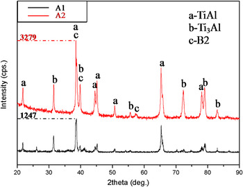
Figure 7 is the XRD pattern of the two alloys. They are composed of most γ-TiAl phase and relatively less α2-Ti3Al and B2 phase. B, Y contained precipitations can not be detected because of their less addition.
XRD patterns of A1 and A2 alloys.

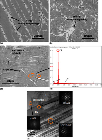
Figure 8 shows the microstructure of the two alloys by SEM and TEM before HT. From Figs. 8(a) and 8(b), both of them are composed of (α2 + γ) lamella colony and (B2 + γ) blocky morphology, and some B, Y contained precipitations can be found in A2 [see Fig. 8(b)]. The colony size of A2 is smaller than that of A1, A1 alloy yields the average colony size about 1100 μm and that of A2 is 300 μm or so. According to Yang' research, Reference Yang32 the refining effect of B on as-cast TiAl-based alloys has a so-called “on–off” effect: “when its addition is 0–0.5%, no obvious refining effect can be found; when the addition is more than 0.5%, remarkable refining can be realized.” However, obvious refining can be observed for A2, which is mainly attributed to the following reasons: firstly, the research parts in the large ingot may have the special heat transmission condition during VCM that can affect the colony size; secondly, the addition of Y can also refine the microstructure; thirdly, the (B2 + γ) blocky morphology is more dispersed, which can further refine the microstructure. From Fig. 8(c), the stripe shaped TiB and Y contained precipitation [detected by EDS in Fig. 8(d)] can be found. It is noted that there are lots of microcracks in the blocky γ phase, which will be harmful for the mechanical properties of brittle materials. From Fig. 8(e), typical microstructure and phase composition are investigated by TEM, the selected area diffraction patterns (SADPs) are illustrated in this figure and the dislocations can be found in blocky γ (this sample is derived from the tensile testing sample).
Microstructure of original as-cast alloys by VCM: (a) A1 alloy; (b) A2 alloy; (c) A2 alloy at a larger magnification; (d) EDS testing result of the Y-contained precipitation region; (e) TEM observation of A1 alloy after RT tensile testing and the corresponding SADPs.

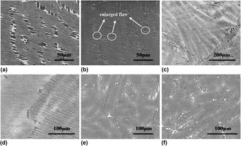
Figure 9 shows some HT microstructure. From Fig. 9(a), HT1 can reduce B2 phase and (B2 + γ) blocky morphology at a certain degree, but there is still more residual in the local regions. Figure 9(b) is the SEM-SE image of Fig. 9(a) that lots of defects can be observed clearly. These defects may be originated from the VCM ingot, and after HT1, they are enlarged obviously. Given that TiAl-based alloy is brittle and sensitive to thermal stress, relatively lower heating and cooling rate and ladder cooling are used in the other HT schedules. Figures 9(c) and 9(d) is the microstructure of A1 after HT3 and HT4, and they are similar with each other, since the annealing temperature is approximate, and B2 and (B2 + γ) blocky morphology have been eliminated obviously compared to Figs. 8(a) and 9(a). Figure 9(e) exhibits the microstructure of A2 after HT4, and compared to the original microstructure in Fig. 8(b), similar changing as above can also be found. Except for a small quantity of white B2 phase, there are some white B, Y contained precipitations with the brighter constant. Figure 9(f) exhibits the microstructure of A2 after HT5 and it is similar as that of Fig. 9(e), and moreover, the colony size has been decreased to around 75 μm that is notably refined from the original microstructure, and it is interesting that almost no defects can be found in the HT5 microstructure.
Microstructure of VCM alloys after HT: (a) A1 alloy by HT1 and (b) corresponding SEM-SE image; (c) A1 alloy by HT3; (d) A1 alloy by HT4; (e) A2 alloy by HT4; (f) A2 alloy by HT5.

E. Ma/microstructure evolution of CCDS ingots before and after HT
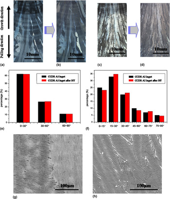
HT3 is used on CCDS ingots and the experimental results are exhibited in Fig. 10. Figures 10(a) and 10(b) (Ref. Reference Dong, Chen, Guo, Ding, Su and Fu11) exhibits the macrostructure of CCDS A1 before and after HT respectively. It finds that the DS macrostructure can be reserved after HT. Figures 10(c) and 10(d) (Ref. Reference Dong, Chen, Guo, Ding, Su and Fu19) exhibits the macrostructure of CCDS A2 before and after HT, respectively, and similarly, its DS macrostructure can also be reserved. Furthermore, the lamella angle is investigated, as shown in Figs. 10(e) and 10(f). It indicates that the original lamella orientation is almost not changed after HT, i.e. the small angle lamellas have been reserved. The microstructure is shown in Figs. 10(g) and 10(h). Compared to original CCDS microstructure [similar as Figs. 8(a) and 9(b)], the B2 phase here is reduced obviously [similar as Figs. 9(c)–9(f)]. Because no or less casting defect can be generated by CCDS, Reference Dong, Chen, Guo, Ding, Su and Fu11,Reference Dong, Chen, Guo, Ding, Su and Fu19 there is also less defect in the HT ingots.
Experimental results for CCDS ingots after HT3: (a) macrostructure of CCDS A1 alloy before HT and (b) after HT; (c) macrostructure of CCDS A2 alloy before HT and (d) after HT; (e) statistical result of lamella orientation of CCDS A1 alloy and (f) that of CCDS A2 alloy; (g) microstructure of CCDS A1 alloy after HT, and (h) that of CCDS A2 alloy.

F. RT tensile properties
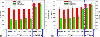
The RT tensile property is shown in Fig. 11, where (a) and (b) are for A1 and A2 alloy, respectively. From Fig. 11(a), it finds that the tensile property of VCM A1 alloy is not improved by HT, although B2 phase and (B2 + γ) morphology have been eliminated effectively [see Figs. 9(a)–9(d)]. Even that, the ultimate tensile strength (UTS) and the elongation decreased after HT1, which may be resulted from more defects by VCM. The defect cannot be eliminated by annealing, and on the contrary, they may be enlarged after unsuited HT, and moreover, it has the full lamella structure with the larger colony size, therefore it yields a poor elongation. After CCDS, no or less defect can be found by SEM at higher magnification times, and there are the DS macrostructure and a higher percentage of small angle lamellas, Reference Dong, Chen, Guo, Ding, Su and Fu11,Reference Dong, Chen, Guo, Ding, Su and Fu19,Reference Chen, Dong, Guo, Ding, Su and Fu25 thus, A1 yields a better property with average UTS of 589.4 MPa and elongation of 1.16%. After HT3 for the CCDS A1 ingots, not only B2 phase and (B2 + γ) morphology have been eliminated effectively, but also the DS macrostructure and higher percentage of small angle lamellas can be reserved. Furthermore, no or less defects can be found in the HT microstructure that is benefit from the original no-defect CCDS microstructure. As a result, the tensile property after HT is improved, mainly manifested in the elongation that has been increased to the average of 1.30%, Reference Dong, Chen, Guo, Ding, Su and Fu11 which is improved for around 12.1%.
RT tensile property of the two alloys before and after HT: (a) A1 alloy; (b) A2 alloy.

From Fig. 11(b), similarly for the HT A2 by VCM, defect is also the main factor to suppress the tensile property, however there are some differences. HT2 and HT3 schedules can improve the tensile property, which is because that smaller colony size can lower the crack susceptibility (more barriers for crack propagation), and similar results are also found by Huang Reference Huang, Liaw, Liu, Liu and Huang33 and Chen. Reference Ding, Lin, Zhang, Su, Wang and Chen1,Reference Ding, Lin, Zhang, Su and Chen13,Reference Ding, Lin, Zhang, Song and Chen14 It is worth noting that the tensile property can be improved obviously by HT5, and the average elongation can reach to 1.20%, which can be attributed to two factors besides the reduced B2 phase and (B2 + γ) morphology: firstly, the smaller colony size is helpful for improving the tensile property to some extent according to the classical Hall–Patch relationship Reference Nam, Oh, Kumar and Wee34 ; secondly, when it is heat preservation in β phase region, the BCC stacking structure will occupy more space (crystal density K ≈ 0.68 for BCC structure and K ≈ 0.74 for FCC and HCP structure) that can facilitate the closure of defect, and then, the following slower and ladder cooling can avoid the formation of new defect, as a result, the final tensile property is improved. After CCDS, it yields the average UTS of 658.7 MPa and elongation of 1.25%, Reference Dong, Chen, Guo, Ding, Su and Fu19 and its average elongation can reach to 1.42% after HT3, which is increased by around 18.3%.
From the discussions above, for the heavy-alloying high-Nb contained TiAl-based alloys, B2 and (B2 + γ) blocky morphology can be decreased and dispersed by annealing. When the alloys are prepared by CCDS, no casting defect can be produced, and the DS macrostructure and a higher percentage of small angle lamellas can be obtained. On that base, after the suitable HT, it finds that: not only B2 phase can be decreased effectively, but also the DS macrostructure and lamella orientation can be reserved, and ductility is improved at RT.
IV. CONCLUSIONS
From the experimental results and discussions above, the following conclusions can be drawn
-
(1) For A1 and A2 alloys cast by VCM, B2 phase and (B2 + γ) can be reduced obviously by annealing at 1280–1290 °C, in which the RT tensile property of A2 alloy is improved after HT.
-
(2) After HT5 (heat preservation in β phase region, successively at 1290 °C and then ladder cooling), A2 alloy cast by VCM exhibits a further refined colony size and decreased casting defect, and RT tensile elongation can reach to average of 1.20%.
-
(3) For the two CCDS alloys, after HT3, besides the reducing B2 phase and (B2 + γ), DS macrostructure and higher percentage of small angle lamellas can also be reserved. A1 yields elongation of 1.30 ± 0.11% and A2 yields elongation of 1.42 ± 0.10% after HT, which has been increased by 12.1 and 18.3%, respectively.
ACKNOWLEDGMENT
This research was supported by National Basic Research Program of China (2011CB605504) and the Program of New Century Excellent Talents in University (NCET-12-0153) and National Natural Science of Foundation of China (51274076).