Introduction
Electron radiotherapy is used to treat superficial lesions and tumours at shallow depths under the skin. The treatment uses an electron applicator with a cutout to conform the target area. For typical electron radiotherapy in our centre, the radiation oncologist first outlines the shape of the electron field using a pen and transparence, or on the treatment planning system (TPS). Then, he/she prescribes the dose at the depth of maximum dose (d m) or the isodose contour such as 80 or 90%, and decides which electron beam energy, treatment distance and size of applicator will be used. The treatment setup and dose prescription details are sent to a radiotherapist or dosimetrist, who is going to fabricate the electron cutout inserted to the applicator in the mould room. Cutouts are made of low melting point alloys such as Belmont Metal (2531RT, Belmont Metals Inc., Brooklyn). The composition of this alloy is: 52.5% of Bismuth, 32.0% of Lead and 15.5% of Tin. The melting point of the alloy is 95°C and its mass density is 9.7 g/cm3 at 20°C. The thickness of the cutout is 1.5 ± 0.2 cm and its inner edge is straight and non-divergent. To calculate the monitor unit (MU) for the treatment, the relative output factor (ROF), which is defined as the ratio of the dose rate in water at a reference point with a custom cutout to the dose rate under the beam calibration condition, is predicted by measurementReference Chow and Newman1, using an in-house electron MU calculatorReference Chen, VanDyk, Lewis and Battista2, Reference Chow, Grigorov and MacGregor3 or an electron TPSReference Hogstrom, Mills and Almond4–Reference Glegg6. In the above procedures, as the prescribed dose is delivered at a depth along the central beam axis (CAX) in the electron field, the isocentre of the linear accelerator (linac) is expected to be at the cutout centre. Achieving such an alignment depends on the skill of the radiotherapist/technologist in the mould room. There may be human variation in centring the electron field with the machine CAX during the fabrication. In general, an uncertainty of ±5 mm can be found in locating the centre of the field to the machine CAX. The dosimetric changes owing to this uncertainty are not significant when the treatment field is large and the beam energy is relatively low with a short electron path length (e.g. 4 MeV). However, due to the effect of electron disequilibrium, such uncertainty would cause problems when the cutout is small and the electron energy is high (e.g. 16 MeV).Reference Rustgi and Working7–Reference Boyd, Hogstrom, White and Starkschall9 The beam characteristics such as d m, ROF and depths of the 80 % (R80) and 90 % (R90) depth dose would therefore be changed, when the cutout is small and the beam energy is high.10 The positional uncertainty of centring the cutout at the machine CAX would in turn contribute uncertainty in the treatment delivery. The aim of this study is to investigate the dosimetric changes caused by such uncertainty for small electron field, focusing on the beam dosimetry of a small circular cutout (diameter = 4 cm) for a 6 × 6 cm2 applicator. Three electron beam energies namely, 4, 9 and 16 MeV produced by a Varian 21 EX linac were used.
Materials and methods
The effects of the positional uncertainty, caused by centring the electron cutout to the machine CAX, in the electron beam characteristics such as d m, R80, R90 and ROF were investigated.
Small circular cutouts
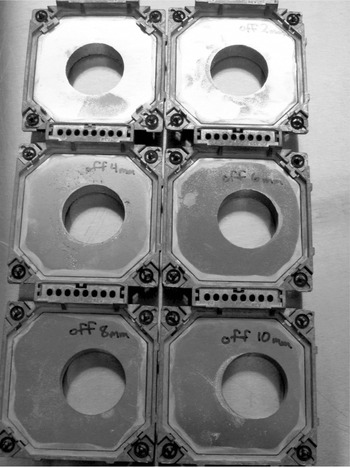
Six circular cutouts with diameters equal to 4 cm were fabricated for the 6 × 6 cm2 applicator in the mould room. The cutout centres were shifted with 0, 2, 4, 6, 8 and 10 mm towards the positive horizontal axis of the frame as shown in Figure 1. They were all fabricated at the same time in the mould room to guarantee they had the same material quality. The positional uncertainty between the cutout centre and the machine CAX was kept less than ±2% by careful quality assurance (QA) testing, using a digital slide caliper and the optical field of the linac. The whole group of cutouts was remade if any of them were found to have a positional error larger than ±2% in the QA test.
Diagram showing the six circular cutouts for the 6 × 6 cm2 applicator used in this study. The diameter of all cutouts is 4 cm. The cutout in the left-hand corner is centring at the machine central beam axis, and the one on its right has its centre off the machine central axis for 2 mm along the horizontal axis. The positional accuracy of the cutout was kept within ±2%.

Beam profile and percentage depth dose measurements
The beam profiles (BPs) of the in-line (between the Y1 and Y2 jaw) and cross-line (between the X1 and X2 jaw) axis at d m were measured for all six cutouts using the 4, 9 and 16 MeV electron beams. For the percentage depth doses (PDDs), both curves at the machine CAX and cutout centre were measured. When either the 4 or 9 MeV electron beam was used for the 6 × 6 cm2 applicator, the jaws were automatically set at 20 × 20 cm2. For 16 MeV beam, the jaws were set at 11 × 11 cm2. A big scanning water tank system (RFA 300, Scanditronix Medical AB with Omni Pro 6 software) typically used for machine commissioning was used for the measurements. A waterproof high-doped p-type silicon diode (Scanditronix Medical AB, EFD-3G) detector was used to measure both the PDDs and BPs. The thickness of the silicon chip was 0.5 mm and the diameter of the active area was 2 mm. Because the circular cutouts were too small to put a reference detector in the beam path, the reference dose signal for the measurements was obtained from the internal monitoring ionisation chamber within the gantry head. In order to align the cutout centre with the machine CAX, the vertical isocentre axis for the PDD curve was located according to the peak position of the cross- and in-line axis BPs for the measurement. This was particularly important when performing the PDD measurement for a small field using relative low energy (e.g. 4 MeV), where the beam penumbras were relatively large for such energy due to electron disequilibrium. The diode detector was positioned vertically, perpendicular to the water surface. This setting made the sampling resolution dependent on the thickness of the diode sensitive volume (∼0.5 mm). The position of the sensitive region from the detector front surface was provided by the manufacturer and verified in this study, and was taken to be the effective point of measurement. A depth ionisation curve was scanned first to determine the position of d m before the BP scanning. Then, the sensitive volume of the diode detector was positioned at the located d m and the BPs along the cross- and in-line direction were scanned. The position of the surface was determined by noting the dose variation in the diode detector reading at the water-air interface. Percentage depth ionisation (PDI) curves were measured with a sampling resolution of 1 mm and the slowest speed. The dose sampling rate of the diode detector was chosen to be at least 20 because of the unstable nature of the electron beam. All measurements were taken using a source-to-surface distance (SSD) of 100 cm with an air gap of 5 cm. These measurements were carefully repeated one by one within the same day. It was found that the repeated scan agreed with the original results within ±0.5%. The SSD and zero-water-level were checked frequently to prevent any physical effects, such as evaporation, from introducing measurement error. The radiation characteristics of the diode detector was verified with the ionisation chamber to confirm that the depth ionisation curve obtained by the diode could be used as the depth dose curve without correction.Reference Ding and Yu11, Reference Sharma, Supe, Anantha and Subbarangaiah12
ROF measurement
The ROFs of the circular cutouts at the cutout centre and the machine CAX were measured using a water tank and a waterproof micro-ionisation chamber (Scanditronix Medical AB, RK8304). The electron beam energies of 4, 9 and 16 MeV were used. The chamber has air cavity volume of 0.12 cm3 and air cavity diameter of 4 mm. The SSD was set at 100 cm and the distance between the bottom of the applicator and the water surface was 5 cm. The outputs measured using the circular cutouts were normalised to that in the absolute calibration condition. For the linac used in this study, the absolute dose point was calibrated at the reference depth (d ref) defined by the AAPM TG-51 protocol using the 10 × 10 cm2 applicator and the standard 10 × 10 cm2 cutout.Reference Almond, Biggs, Coursey, Hanson, Huq, Nath and Rogers13, Reference Cho, Lowenstein, Balter, Wells and Hanson14 In this study, the reference dose point for the ROF measurements was set at d m.
Results and discussion
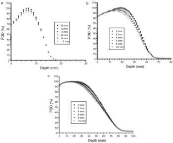
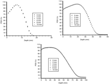
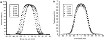
When the PDDs are measured at the machine CAX for the six cutouts with different off-axis distances between the cutout centre and machine CAX from 0 to 10 mm, the d m change for the 9 and 16 MeV electron beams is shown in Figure 2b,c. When the cutout centre shifts off from the machine CAX, the d m becomes closer to the water surface. The change of d m for the 4 MeV beams, however, is negligible (<0.1 mm) as shown in Figure 2a. Similarly, the R 80 and R 90 for the 9 and 16 MeV electron beams shift closer to the water surface, when the off-axis distance between the cutout centre and the machine CAX increases. As the treatment dose is prescribed at the d m, R 80 or R 90, such change of prescription point position for the small cutout should be noted. The outputs of the PDDs are also affected by the off-axis distance. This effect was seen for all three electron beam energies as shown in Figure 2. Anyhow, when the PDDs are measured at the cutout centre as shown in Figure 3a–c for the 4, 9 and 16 MeV electron beams, respectively, the effect of the off-axis shift on the d m, R 80, R 90 and ROF disappears. The PDD curves do not change when the cutout centre is shifting away from the machine CAX. Therefore, if a physicist or dosimetrist measures the PDD and ROF by positioning the dosimeter at the cutout centre, the dosimetric uncertainty could be avoided. However, because the radiation oncologist prescribed the dose before the cutout is fabricated, the machine CAX is still used for the measurements. Figure 4a,b shows the BPs along the cross- and in-line axis for the 4 MeV electron beams, respectively. All profiles are normalised to the d m of the profile with the cutout centred at the machine CAX. In Figure 4a, it can be seen that the profiles measured at the d m shifts to the positive cross-line direction according to the off-axis distances of the cutouts. This cannot be seen in Figure 4b because the in-line axis profiles are measured perpendicular to the shift of the cutout centre. However, in both figures, it is found that the relative output is reduced when the cutout centre is shifted from the machine CAX. Because of that, the isodose coverage of the profiles is reduced when the cutout centre is shifting off as shown in Figure 4b. Again, this would generate dosimetric uncertainty complications to the dose prescription in the treatment.
Percentage depth dose curves of the six cutouts measured at the machine central beam axis using the (a) 4 MeV, (b) 9 MeV and (c) 16 MeV electron beams. All curves are normalised to the maximum dose of the circular cutout centring at the machine central beam axis.

Percentage depth dose curves of the six cutouts measured at the cutout centre using the (a) 4 MeV, (b) 9 MeV and (c) 16 MeV electron beams. All curves are normalised to the maximum dose of the circular cutout centring at the machine central beam axis.

Beam profiles of the six cutouts measured along the (a) cross-line axis and (b) in-line axis using the 4 MeV electron beam.

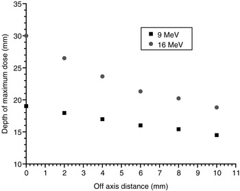
To investigate the changes of d m for the 9 and 16 MeV electron beams in greater detail, the d m was plotted against the off-axis distances as shown in Figure 5. In the figure, the reduction of d m for the 9 MeV beam is about 0.45 mm per mm shift of the cutout centre. For the 16 MeV beam, within the first 4 mm shift, the reduction of d m is about 1.63 mm per mm shift of the cutout centre. Because the change of d m with the off-axis shift is negligible for the 4 MeV beam, it is believed that the change of d m with the off-axis distance is significant only when using relatively high electron beam energy with small cutout.
Diagram showing the variation of the dm with the off-axis distance between the cutout centre and machine central beam axis for the 4, 9 and 16 MeV electron beams.

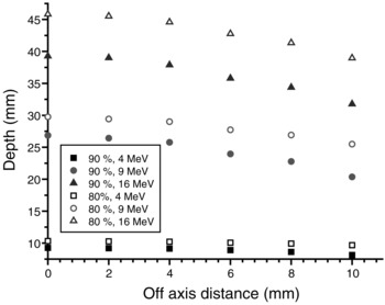
Figure 6 shows the variations of the R 80 and R 90, measured at the cutout centre and machine CAX, behind the d m with the off-axis distance for the six cutouts using the 4, 9 and 16 MeV electron beams. For a small cutout and electron beam with low energy of 4 MeV, the reductions of R 80 and R 90 are smaller than 0.1 mm per mm off-axis shift. However, for the 9 and 16 MeV electron beams, the reductions of R 80 and R 90 for both energies are all about 0.7 mm per mm off-axis shift when the off-axis distance >4 mm.
Diagram showing the variations of R80 and R90 with the off-axis distance between the cutout centre and the machine central beam axis for the 9 and 16 MeV electron beams.

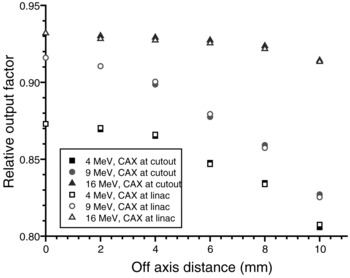
Figure 7 shows the ROFs plotted against the off-axis distance for the six cutouts using the 4, 9 and 16 MeV electron beams. The ROF is normalised to the 10 × 10 cm2 applicator and 10 × 10 cm2 cutout using SSD = 100 cm at d m. In Figure 7, it can be seen that both the ROFs measured at the cutout centre and the machine CAX are very close for the 4, 9 and 16 MeV electron beams. For a typical positional uncertainty of 4 mm for centring a circular cutout to the machine CAX, the ROFs measured at the CAX for the 4, 9 and 16 MeV electron beams are reduced by 0.8, 1.6 and 0.5%, respectively. It should be noted that although each of the dosimetric changes (such as d m and ROF) are relatively small compared with the total electron radiotherapy uncertainty of ± 5%,Reference Brahme15, Reference Van Dyk, Barnett, Cygler and Shragge16 the sum of them may be large enough to induce significant complications in the treatment, especially when the cutout is small and using a high energy electron beam.
Diagram showing the variation of the relative output factor measured at the cutout centre and machine central beam axis with their off-axis distance for the 4, 9 and 16 MeV electron beams.

Using the measured data in this study, a clinical example of electron radiotherapy for a conjunctiva patient illustrates the impact of the positional uncertainty of the cutout in the dose delivery. A 16 MeV electron beam with a circular cutout of 5 cm diameter was used to treat the patient’s eye orbit with treatment depth equal to 3 cm, and SSD = 100 cm. The prescribed dose was 25 Gy/10 fractions. With a 4 mm shift of the centre of the cutout (or tolerance level of ±4 mm), the shift of the PDD towards the patient’s surface results in a reduction of delivered dose equal to about 1.5%. For the dose distribution, the 80 and 90% contour are moved 1.3 and 1.6 mm downwards from the patient’s surface. When the centre of the cutout is shifted 2 mm from the machine CAX (or tolerance level of ± 2 mm), the delivered dose was found to be reduced by about 0.5%. There is also negligible change of the 80 and 90% contour in the plan. It is therefore recommended that a tolerance level of ±2 mm should be used for the positional uncertainty QA, when fabricating the electron cutout, especially when electron beam with high energy and small field size was used.
Conclusions
The dosimetric changes caused by the positional uncertainty of centring a small cutout to the machine CAX were investigated. The dependences of the PDDs, BPs, d m, R 80, R 90 and ROF on the shift of the centre of the cutout were determined using different electron beams with energies of 6, 9 and 16 MeV. The effect of the dosimetric change owing to different tolerance levels of the positional uncertainty of cutout was evaluated by a clinical example using a 16 MeV electron beam. It is recommended that a tolerance level of ±2 mm should be used in the QA process for the cutout centring, to ensure negligible change of the prescribed dose and dose distribution in the dose delivery. Although the electron treatment uncertainty would be patient specific clinically, radiation oncologists, dosimetrists and radiotherapists are advised to note the above dosimetric uncertainties, when prescribing dose and fabricating cutout for electron radiotherapy. Creating a database to record the positional uncertainties corresponding to the dosimetric parameters of PDDs, BPs, d m, R 80, R 90 and ROF is also recommended.