I. INTRODUCTION
Rapid development of multiband wireless communication systems has been gaining much interest in recent years. As a key component in the radio frequency front-end, multi-bandpass filters (BPFs) with compact size and high performance have been in great demand to meet current growing trend [Reference Chen, Chu and Tu1–Reference Feng6]. In [Reference Chen, Chu and Tu1], a tri-band BPF was implemented by cascading three pairs of microstrip resonators, which leads to a relatively large circuit size. For the compact size and good roll-off skirt, stub-loaded resonators (SLRs) were utilized to realize the first and third passbands, while an additional half-wavelength microstrip resonator was used to excite the second passband; however, the structure is relatively complicated [Reference Chu, Wu and Chen2]. In [Reference Li, Zhang, Feng and Fan3], the mode-splitting technique is applied to design tri-band BPF; however, the flexible design with high isolation and selectivity of three passbands still need to be improved.
Recently, a tri-band filter based on an asymmetrically stub-loaded UIR (uniform impedance resonator) with good design flexibility and excellent out-band performance was reported in [Reference Lan, Weng, Chang, Hung and Liu4]. In [Reference Chen, Weng and Chang5], a stub-loaded stepped-impedance resonator (SL-SIR) was proposed for using in a tri-band BPF, providing multi-design freedoms by combining the SLR with the SIR. Also, a tri-band high-temperature superconductor (HTS) BPF using SL-SIR has been reported in [Reference Feng6]. Nevertheless, only few attempts have so far been proposed to design a tri-band BPF using asymmetric SL-SIRs with multiple transmission zeros (TZs).
To enhance the design flexibility, a tri-band BPF using asymmetric SL-SIR and novel feedline structure is proposed in this letter. Owing to the mixed-type feedline structure, the M ij and Q e i can be controlled to meet the required bandwidth for the three passbands. Moreover, multiple TZs can be produced to improve the isolation between each of the passbands. Finally, the tri-band filter is fabricated and the experimental verification is provided.
II. RESONANCE OF ASYMMETRIC SL-SIR
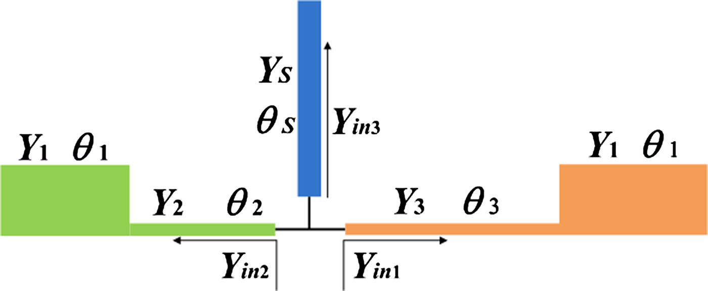
Figure 1 shows a configuration of the proposed asymmetric SL-SIR. It consists of two different SIRs and an open stub. Y in1, Y in2, and Y in3 represent the characteristic admittances of three open shunt segments from the joint to three different directions. Then, the input admittance of this resonator can be derived as:
 $$Y_{in} = Y_{in{\rm 1}} + Y_{in{\rm 2}} + Y_{in{\rm 3}}, $$
where
 $$Y_{in{\rm 1}} = Y_3 \displaystyle{{jY_1 \tan \theta _1 + jY_3 \tan \theta _3} \over {Y_3 - Y_1 \tan \theta _1 \tan \theta _3}}, $$
 $$Y_{in{\rm 2}} = Y_2 \displaystyle{{jY_1 \tan \theta _1 + jY_2 \tan \theta _2} \over {Y_2 - Y_1 \tan \theta _1 \tan \theta _2}}, $$
 $$Y_{in{\rm 3}} = jY_s \tan \theta _s. $$
Its resonance condition can be expressed as:
 $$Im(Y_{in} ) = 0.$$
Substituting (1)–(4) into (5), in this work, Y 2 = Y 3 = Y s is assumed for simplicity. Thus, the resonance condition can be expressed as:
 $$\eqalign{& 2kC_1 (1 - C_{\alpha T} C_{{\rm (1} - \alpha {\rm )}T} ) + (k^2 - C^2 _1 )(C_{\alpha T} + C_{{\rm (1} - \alpha {\rm )}T} ) \cr & \quad + C_S (k - C_1 C_{{\rm (1} - \alpha {\rm )}T} )(k - C_1 C_{\alpha T} ) = 0,} $$
where C 1, C αT , C (1−α)T , and C S stand for tanθ 1, tanαθ T , tan(1 − α)θ T , and tanθ S , respectively. θ T , α, and k represent the total length (θ 2 + θ 3), asymmetric electrical length ratios (θ 2/θ T ), and admittance ratio (Y 2/Y 1), respectively. Based on (6), it is noted that the proposed asymmetrical SL-SIR has more degrees of design freedom than the conventional SL-SIR. The proposed asymmetric SL-SIRs can provide a flexible way to tune the three resonant frequencies.
Configuration of asymmetric SL-SIR.

III. TRI-BAND FILTER DESIGN
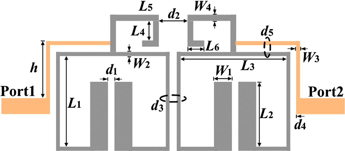
In this section, a tri-band BPF operated at 1.92/3.2/5.8 GHz is illustrated in Fig. 2. It consists of two asymmetric SL-SIRs and a mixed-type feedline structure. The former is utilized to generate three resonant modes. The latter is designed by tapped feedline with coupled feedline, which can independently adjust Q e for multiband design.
Layout of the designed tri-band filter.

A) Center frequencies and physical dimensions
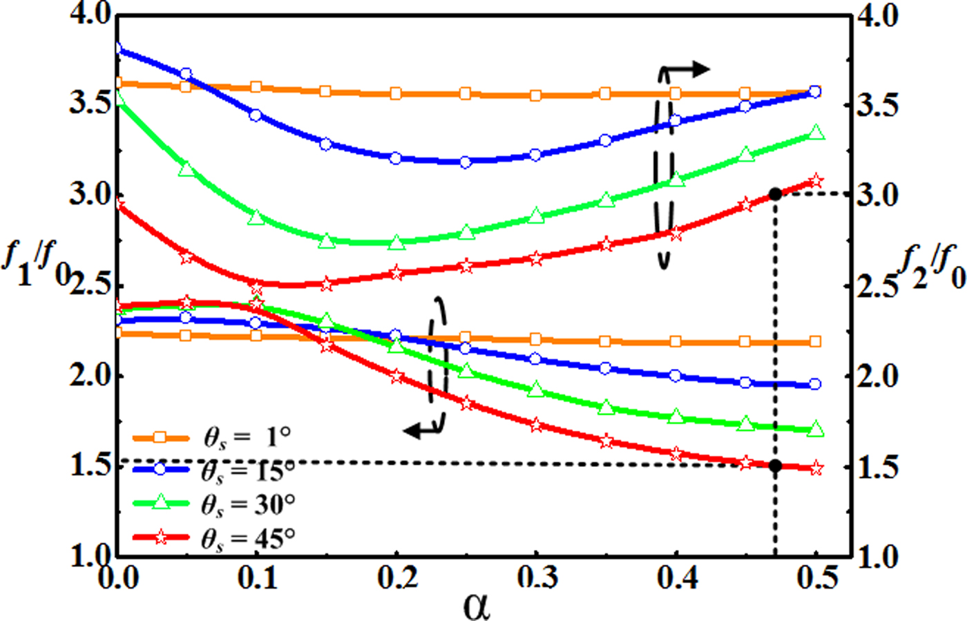
Following the design method described in Section II, the fundamental frequency f 0 is designed at 1.92 GHz. Based on the theory of SIR [Reference Makimoto and Yamashita7], the θ 1 = 21°, θ T = 107.5°, k = 1.89 can be chosen accordingly. The normalized frequency ratios f 1/f 0 and f 2/f 0 of the asymmetric SL-SIR can be easily realized versus α with different θ s , which is depicted in Fig. 3. In this example, f 1/f 0 and f 2/f 0 are calculated to approximately 1.67 and 3.02, respectively. By drawing these frequency ratios in Fig. 3, the suitable α and θ s are chosen to about 0.465 and 45°. Accordingly, its physical dimensions can be determined by these extracted values. However, considering the effect of coupled sections after bending the resonator, a parameter optimization method is utilized to achieve target specifications in this paper. The optimized geometric parameters are as follows: L 1 = 7.5, L 2 = 5.55, L 3 = 8.1, L 4 = 2.9, L 5 = 3.6, L 6 = 2.25, W 1 = 1.25, W 2 = 0.3, W 3 = 0.2, and W 4 = 0.5 (all units are in mm).
Frequency ratios f 1/f 0 and f 2/f 0 versus asymmetric α with different θ s .

The current density distributions of the proposed asymmetric SL-SIR at the three resonant modes of 1.88, 3.2, and 5.8 GHz, respectively, are shown in Fig. 4. This verifies that the asymmetric SL-SIR produces three modes.
Current density distributions at the resonant frequencies: (a) 1.88, (b) 3.2, and (c) 5.8 GHz.

B) External quality factor and coupling coefficient
The proposed tri-band filter is designed with the target specifications, the corresponding fractional bandwidths (FBWs) of FBWI = 6%, FBWII = 4%, and FBWIII = 8.57%, respectively. The lumped circuit element values for Chebyshev low-pass prototype filter with a 0.5-dB ripple level are found to be g 0 = 1.0, g 1 = 1.4029, g 2 = 0.7071, and g 3 = 1.9841.
The theoretically prescribed coupling coefficients M ij and external quality factor Q ei , defined in (7) and (8), as follows [Reference Hong and Lancaster8]:
 $$M_{ij} = \displaystyle{{FBW} \over {\sqrt {g_i g_j}}}, $$
 $$Q_{ei} = \displaystyle{{g_0 g_1} \over {FBW}}.$$
Combining with the design specifications of the filter, herein, the M ij and Q ei can be calculated as M 12 I = 0.06 and Q e1 = 23.38 for the first passband, M 12 II = 0.04 and Q e2 = 35.07 for the second passband, and M 12 III = 0.086 and Q e3 = 16.37 for the third passband.
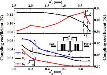
The Q ei are utilized to determine feedline position h and coupled spacing d 4 under the preset conditions of d 5 = 0.4 mm and W 3 = 0.2 mm, and the M ij can be used to determine the gap d 2 and d 3 between the two resonators. With the help of full-wave electromagnetic simulator Sonnet [9], M ij and Q ei can be extracted by using the following equation [Reference Liu, Ren, Guan, Wen and Wang10]:
 $$Q_{ei} = \displaystyle{{f_{0i}} \over {\Delta f_{ \pm {\rm 90}^{\circ}}}}, \quad i{\rm = 1,}\;{\rm 2,}\;{\rm or}\;{\rm 3,}$$
 $$M_{ij} = \displaystyle{{f_H^2 - f_L^{\rm 2}} \over {f_H^2 + f_L^2}}, $$
where Δf ± 90° is the bandwidth of the resonant frequency over which the phase varies from −90° to +90°. The f H and f L represent the lower and higher frequency of the two coupling modes, respectively.
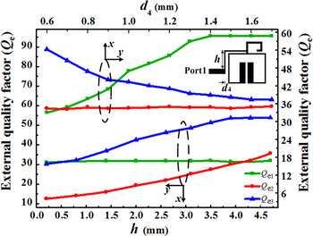
Simulated Q ei for the three passbands versus coupling gap d 4 and feedline height h is shown in Fig. 5, it can be observed that Q e1 and Q e3 change significantly while Q e2 keeps to a constant as d 4 increases. Similarly, Q e1 approaches a constant when the position of the feedline h goes up. In addition, the coupling strength between the asymmetric SL-SIRs are simulated and shown in Fig. 6; it is seen that more design data can be obtained by choosing different d 2 and d 3 combinations to meet the desired coupling coefficients. In this procedure of filter design, different physical parameters can be properly chosen to achieve the required Q e and M ij at the three passbands simultaneously. Following the above-mentioned design steps, the parameters of the coupling structure can be determined. The final results are as follows: d 2 = 1.2, d 3 = d 4 = 0.4, d 5 = 0.2, w 3 = 0.2, and h = 4.7 (all units are in mm).
External quality factors for the three passbands with different coupling gap d 4 and feedline height h.

Coupling coefficient versus the gap d 2 and d 3.

IV. EXPERIMENTAL RESULTS AND DISCUSSION
From the above discussion, a tri-band microstrip BPF has been designed. It is simulated by Sonnet. It was fabricated on a substrate with relative dielectric constant ε r = 3.5 and thickness of 0.8 mm. The dimension parameters in Fig. 2 are as follows: L 1 = 7.5, L 2 = 5.55, L 3 = 8.1, L 4 = 2.9, L 5 = 3.6, L 6 = 2.25, W 1 = 1.25, W 2 = 0.3, W 3 = 0.2, W 4 = 0.5, d 1 = 0.3, d 2 = 1.2, d 3 = d 4 = 0.4, d 5 = 0.2, and h = 4.7 (all units are in mm).
Simulation and measurement frequency responses of the proposed tri-band BPF are compared in Fig. 7. Results show that the designed tri-band BPF is operated at 1.9 GHz (time division long term evolution – TD-LTE), 3.2 GHz (worldwide interoperability for microwave access – WiMAX), and 5.8 GHz (wireless local area networks – WLAN) with 3-dB FBW of 6, 4, and 8.57%, respectively. The fabricated filter occupies only about 25.1× 9.75 mm2 (about 0.14 λ g × 0.07 λ g , where λ g is the guided wavelength on the substrate at the center frequency of the first passband). The measured insertion loss are 1.03, 0.94, and 1.27 dB, respectively. Note that the frequency response displays four TZs at 1.5, 2.18, 2.36, and 3.46 GHz, which are explained by the transversal signal interference, as studied in [Reference Wang, Wang, Wang and Zhang11, Reference Gómez-García, Muñoz-Ferreras and Sánchez-Renedo12].
Frequency responses of the fabricated tri-band filter.

Table 1 compares the proposed filter with other reported tri-band BPF using similar resonator. It can be observed that the proposed work realizes a tri-band BPF with low insertion loss, compact size, and high band-to-band isolation level. In spite of this, there still exist some limitations for choosing the arbitrary bandwidths of three passbands, and it would be improved in future work.
Performance comparison with reported similar tri-band BPF.

V. CONCLUSION
In this paper, a tri-band BPF has been designed by using asymmetrical SL-SIR with a mixed-type feedline structure. Owing to the feedline structure, the M and Q e can be controlled to meet the required bandwidth for the three passbands. Four extra TZs are created to improve the selectivity of the passbands selectivity. Measured results agree well with the simulation. This design is suitable to multi-band wireless communication devices and systems.
ACKNOWLEDGEMENTS
This work was supported by the National Science Foundation of China (grant numbers 61461020 and U1431110) and Science and Technology Project of Jiangxi Province (grant numbers 20141BDH80002 and 20142BCB24004).
 Haiwen Liu received the B.S. degree in Electronic System and the M.S. degree in Radio Physics from Wuhan University, Wuhan, China, in 1997 and 2000, respectively, and the Ph.D. degree in Microwave Engineering from Shanghai Jiao Tong University, Shanghai, China, in 2004. From 2004 to 2006, he was with Waseda University, Kitakyushu, Japan, as a Research Assistant Professor. From 2006 to 2007, he was a Research Fellow with Kiel University, Kiel, Germany, where he was granted the Alexander von Humboldt Research Fellowship. From 2007 to 2008, he was a Professor with the Institute of Optics and Electronics, Chengdu, China, where he was supported by the 100 Talents Program of Chinese Academy of Sciences. Since 2009, he has been a Chair Professor with East China Jiaotong University, Nanchang, China. His current research interests include high-temperature superconducting circuits, radio frequency and microwave passive circuits, and radar system.
 Fan Liu received the B.S. degree in Communication Engineering from East China Jiaotong University, Nanchang, China, in 2011 and 2015, and he is currently working toward the M.S. degree in Communication and Information System from East China Jiaotong University, Nanchang, China. His current research interests include microwave passive circuits, high-temperature superconducting circuits, and planar antennas for wireless communications.
 Baoping Ren received the B.S. degree in Communication Engineering and the M.S. degree in Communication and Information System from East China Jiaotong University, Nanchang, China, in 2011 and 2014, respectively. He is currently working toward the Ph.D. degree with the Graduate School of Science and Engineering, Saitama University, Saitama, Japan. He is with the School of Information Engineering, East China Jiaotong University. His current research interests include the development of microwave and millimeter-wave circuits, high-temperature superconducting microwave passive devices.
 Aiping Yao received the B.S. degree in Biomedical Engineering from Central South University, Changsha, China, in 2006 and 2010, and M.S. degree in Microelectronics from Chinese Academy of Sciences, Shenzhen, China, in 2010 and 2013. Her current research interests include microwave passive circuits and integrate circuits.
 Xiang Xiao received the B.S. degree in Computer Science and Technology from Central South University of Forestry and Technology, Changsha, China, 2008, and the M.S. degree in Computer Application Technology from East China Jiaotong University, Nanchang, China, in 2013. He is currently the Laboratory Assistant for School of Information Engineering, in East China Jiaotong University. His current research interests include microwave filters, high-temperature superconducting circuits.
 Yunxiu Yang was born in Tangshan, China, in 1994. She is going to receive the B.S. degree in Communication Engineering from East China Jiaotong University, Nanchang, China, in 2017, respectively. Her currently research interests include antenna theory and design, and superconducting filter design.
 Xuehui Guan received the B.S. degree in Communication Engineering from Jiangxi Normal University, Nanchang, China, in 1988, and the Ph.D. degree in Electromagnetic Fields and Microwave Techniques from Shanghai University, Shanghai, China, in 2007. Since June 2007, he has been an Associate Professor with the School of Information Engineering, East China Jiaotong University, Nanchang, China. In 2012, he was a Senior Researcher Associate with the School of Electrical and Electronic Engineering, City University of Hong Kong, Kowloon, Hong Kong. Since June 2013, he has been a Visiting Scholar with the School of Electrical and Electronic Engineering, Nanyang Technological University, Singapore. His current research interests include radio frequency and microwave passive.