Introduction
Earth exploration satellite services involve a study made on the environmental conditions of the earth and its atmosphere using the data collected by several active and passive sensors. Under all weather conditions, such data retrieved from vital measurements made on land, sea, and atmosphere are communicated to a wide range of users through fixed satellite services and direct broadcast services. Such communication requires high-gain antennas (HGAs) with enhanced performance characteristics and the ability to handle multiple frequencies simultaneously. The HGAs which are commonly used for this purpose generally require multiple feeds resulting in increased implementation complexity [Reference Li, Pu, Tang and Zhu1]. Reflectarray antennas, being spatially fed planar HGA, with their simple profile and enhanced characteristics, provide a wide opportunity to obtain the required multiple resonances [Reference Narayanasamy, Alsath Mohammed, Savarimuthu, Sivasamy and Kanagasabai2]. Several structural and methodological variations such as single-layer dual feed [Reference Su, Yi and Wu3], dual-layer dual feed [Reference Tienda, Encinar, Arrebola, Barba and Carrasco4], dual-layer single feed [Reference Martinez-de-Rioja, Martinez-de-Rioja, Rodriguez-Vaqueiro, Encinar, Pino, Arias and Toso5], single-layer single feed [Reference Deng, Yang, Xu and Li6] with phase-matched concentric elements, and single-layer single feed with integrated elements are employed in the RA to attain multi-resonant performances.
As the frequency ratio, f u/f L, [Reference Qu, Chen, Li, Chen and Xia7] is a vital design aspect in the dual-band RAs and since the water vapor absorption line of 22 GHz is within the K band range, most researchers have developed dual band RAs in the X/Ku ranges and Ku/Ka ranges. Only a few RAs are developed to provide dual-band operation in the K band. A single layer 225-element RA with dual feeds to produce radiation with 22.9 dBi gain at 8.5 GHz and 28.8 dBi gain at 16 GHz is reported in [Reference Su, Yi and Wu3]. The complexity in aligning the dual feed mechanism has resulted in an increased value of SLL and cross-polarization levels at both resonant frequencies. Another dual feed RA with a dual layer sub-reflector [Reference Tienda, Encinar, Arrebola, Barba and Carrasco4] is designed to provide broadband radiation with very low cross-polarization levels. Though a peak gain of 26.2 and 29.7 dBi are obtained at 10.2 and 22 GHz respectively, the complexity in the design of different elements on either side of the sub-reflector substrate and the blockage effect of the feeds paves the way to find a simpler solution to achieve similar performance. To avoid the design complexity and provide a simple fabrication solution through 3-D printing technology, researchers in [Reference Zhu, Yang, Mcgloin, Liao and Xue8] have developed an all-dielectric RA. Multiple layers of dielectric separated by a 1 mm air layer are utilized to produce resonances of peak gain 30.7 dBi at 65 GHz and 23.2 dBi at 24 GHz. The performance of this RA degrades due to the fabrication and resolution tolerance of the 3-D printing. A similar dual-feed metal-only RA [Reference Deng, Xu, Yang and Li9] is developed to produce 29.1 dB gain at 10 GHz and 32.6 dBi gain at 15 GHz. The slot-type phoenix element etched out of a metallic sheet separated from the metallic ground through an air gap of 5 mm provides the required phase variation to design the RA. Though the RA acts as a low-cost solution, more conductor losses degrade the RA performance. In [Reference Hamzavi-Zarghani and Atlasbaf10], the phase variation of the split circular ring through variable rotation technique and elemental size variation of modified Malta cross are utilized to develop RA with frequency selective surface (FSS) backed multi-layer substrate. A high measured gain of 36.7 and 40.2 dBi are obtained at 20.4 and 30.2 GHz with a low SLL of −22.7 and −27.9 dB respectively. Though the mutual coupling between the elements is highly suppressed, the design complexity increases.
Several single-layer single-feed solutions for producing dual band resonances with reduced design and fabrication complexity have been explored by researchers. In these single-layer RAs, either a single element with physical variations to produce dual-band response or different elements for different resonant frequencies are utilized. Researchers have followed complex optimization procedures to achieve phase matching at the different resonant frequencies. In [Reference Deng, Yang, Xu and Li6], an X/Ku RA is designed using elements having a square patch with slots enclosed within a square ring to produce radiations with a peak gain of 23.4 dBi at 8.2 GHz and 25.7 dBi at 13.2 GHz. Since a single concentric element is utilized, to match the phase response observed at the two frequencies, the RA element has several degrees of freedom to be optimized. A similar optimization of multiple parameters is done in [Reference Malfajani and Atlasbaf11] to achieve phase matching in a dual-band RA producing a peak gain of 26.2 dBi at 10.2 GHz and 29.7 dBi at 22 GHz.
To reduce the complexity in optimizing the multiple degrees of freedom involved in the design of concentric elements employed in dual-band RAs, an integrated multi-resonance structure is deployed in an X/Ku band RA [Reference Deng, Xu, Yang and Li9]. 122 elements having a circular ring, two concentric open rings, and the I dipole are developed on a single-layer substrate. 278 dual resonant elements are distributed to provide a peak gain of 17 0.8 and 23.4 dBi at 9 and 13.5 GHz respectively. But, the incompleteness in the phase distribution offered by dual resonant elements has caused the need for four-resonance elements. Hence this RA involves complex design. Another RA with four different structures printed on a dielectric substrate produces quad-band responses at 12, 13, 14, and 15.5 GHz [Reference Hasani, Peixeiro, Skrivervik and Perruisseau-Carrier12]. Phase matching attained by optimizing the concentric elements such as cross dipole, tilted curved dipoles, split circular ring and split square ring offers a peak gain of 22, 20, 25.4, and 26 dBi. Though the SLL and cross-polarization levels are better, the aperture efficiencies are very low.
Hence, to facilitate the communication of data from the earth exploration satellites to fixed and mobile satellites, the design of a low-profile dual-band linearly polarized RA with a 1.58 frequency ratio is reported in this paper. The proposed RA covers the Ku band uplink frequency range required for the fixed satellite services and the K band frequencies utilized by earth exploration satellites. Avoiding the optimization complexities involved in traditional dual-band RA designs, two different elements with reduced mutual coupling are developed to design the proposed RA. A dual concentric ring is arranged co-centric with the source horn to produce resonance at 14.25 GHz. A modified Malta cross with a delay line is distributed off-centric with the source to resonate at 22.5 GHz. The 529 circular rings of the RA provide a peak gain of 28 dBi with an SLL and a cross-polarization value less than −21 and −31 dB respectively. Due to the offset arrangement, the K band elements offer a peak gain of 26.4 dBi with an SLL and a cross-polarization value less than −14 and −28 dB respectively.
The article is organized with a description of the unit cell design and its analysis in section ‘Unit cell design and characterization’. The arrangement of Ku, and K band cells of the RA and the fabrication details are explained in section ‘Reflectarray design’. A report of the simulated and measured results of the proposed RA and a comparative analysis of its performance with other similar RAs is presented in section ‘Experimental analysis’.
Unit cell design and characterization
Two different elements are designed to obtain dual resonance in Ku/K frequency bands with a frequency ratio larger than 1.5. The elements are chosen to have varied surface current distribution and thereby reduce the mutual coupling existing between the neighboring RA elements. As researchers in [Reference Misra and Chowdhury13] have experimentally proved that the bandwidth offered by concentric rings is larger than that offered by a single ring or circular patches [Reference Vidhyashree14], the Ku band resonance is achieved using concentric circular rings whose radius b is determined using the expression stated in [Reference Hsieh and Chang15].

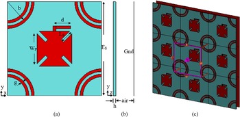
where f L is the Ku band resonant frequency (14.25 GHz), and $\varepsilon _{reff}$ is the effective relative dielectric constant. As the Ku band element is co-centric with the source, a modified Malta cross, placed offset with respect to the source is used as the K band element. These elements are developed on a 0.254 mm thick Rogers RT5870 substrate separated from the ground by a 2 mm air gap. The relative permittivity of the substrate is 2.33 and the loss tangent tan δ is 0.0012. As the element size is 10.5 mm, the periodicity of the integrated elements is 0.5λ 0 and 0.78λ 0 at the resonant frequencies 14.25 and 22.5 GHz respectively. The parametric description of the proposed unit cell and its layers are represented in Figs 1(a) and 1(b).
(a) Unit cell structure, (b) Side view of the unit cell, (c) Infinite array model.

Evolution and parametric analysis
The co-centric and offset alignment of the integrated elements of the dual-band is shown in the infinite array model depicted in Fig. 1(c). The initial design is made in the CST design environment using a circular ring and a Malta cross. The reflection phase and magnitude response of the designed cell is simulated under unit cell boundary conditions in the frequency domain. A phase variation of 290 and 310° are observed at the resonant frequencies through the Floquet ports set. The phase variation is obtained by changing the Malta cross size and the ring size. As the design of RA requires a minimum of 360° phase change, the single circular ring is replaced by a concentric dual circular ring.
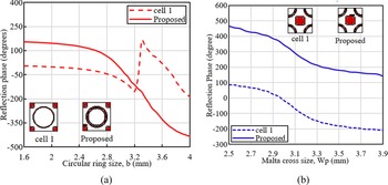
As reported in [Reference Narayanasamy, Mohammed, Savarimuthu, Sivasamy and Kanagasabai16], a reduced gap of 0.25 mm (g 1) is maintained between the concentric rings to increase the mutual coupling between them. The variation in the concentric ring size produces an increased phase variation of 520° at the Ku band resonant frequency, 14.25 GHz. Similarly, the inductive nature of the delay line attached to the Malta cross varies its surface impedance and thereby the current distribution. This variation in the delay line length relative to the Malta size improves the phase range offered by the K band element to 360°. Hence, the minimum 360° phase variation required for designing the proposed dual-band RA is obtained by varying the size of the integrated elements. The evolution of the Ku and K band elements is comparatively portrayed in Figs 2(a) and 2(b) respectively. As the resonance over the two desired bands of operation needs to be individually controlled, the mutual coupling between the integrated elements should be avoided. Hence, the phase variations obtained by controlling their physical changes are done using two independent parameters. The radius, b of the concentric rings decides the resonance frequency. The gap between the concentric rings is maintained minimum to increase their mutual coupling. Hence, the degree of freedom in the Ku band element is restricted to the width of the rings, g.
Evolution of (a) Ku band element, (b) K band element.

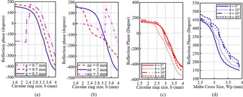
As shown in Fig. 3(a) the ring width is varied and the reflection phase response is observed. Since the phase slope and phase range are almost the same for all three widths, the least value is chosen to avoid the grating lobes which might occur due to the neighboring K band element. As the Malta size, W p, and the delay line length, d are alone the degrees of freedom in the K band element, the effect of air gap thickness over the phase slope and thereby the bandwidth of the unit cell is analyzed as a common factor. Since, as shown in Fig. 3(b), the 2 mm air gap produces a lower phase slope and increased phase range compared to the other values, the optimized design of the proposed unit cell is made with the parameters as shown in Table 1.
Reflection characteristics for different (a) Circular ring width, g (b) air layer thickness, t, (c) angles of incidence at Ku band, (d) angles of incidence at K band.

Parameters of the proposed unit cell

Further, as the periodicity of the K band element is larger than 0.5λ 0, the performance of the reflectarray element in both the bands is observed at various angles of incidence as depicted in Figs 3(c) and 3(d). It is evident that the Ku element deviates in performance at lower angle and K element at larger angle.
Element design and analysis
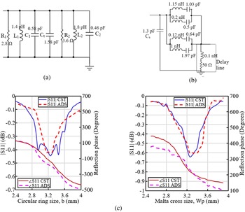
To attain dual resonance with reduced optimization complexity and a large frequency ratio, the integrated elements are designed and analyzed using independent equivalent circuits. The researchers in [Reference Hopkins and Free17] have considered the concentric circular ring element as two microstrip lines separated by a small gap. As shown in Fig. 4(a), these lines are represented as parallel RLC combinations. Their values are obtained using equations (2)–(4) reported in [Reference Ketavath18].


where R 1, L 1, and C 1 are the equivalent parameters of the outer ring whose radius is (b + g),

Electrical equivalents of (a) Ku band element, (b) K band element, (c) Equivalent circuit validation using CST and ADS.

Z 0 is the characteristic impedance, α is the attenuation constant, R 2, L 2, and C 2 are the equivalent parameters of the inner ring whose radius is (b − g 1), and C t represents the summation of the capacitance effect due to the gap between rings, the gap between the substrate and ground, and the fringing capacitance.
Similarly, the equivalent circuit of the K band element is obtained as described in [Reference Saravanan and Rangachar19]. The inductive parts of the Malta cross and the four diagonal slots are represented using the parallel LC combinations as depicted in Fig. 4(b). The capacitance between the substrate and the ground is included as C s in the equivalent circuit. These computations are validated by comparing the corresponding reflection characteristics obtained from CST and the S parameter results of the equivalent circuit simulated in the ADS environment. The comparative results are reported in Fig. 4(c).
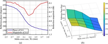
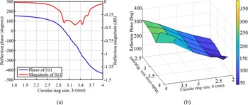
Considering the influence of the neighboring Ku band element, the reflection characteristics of the K band element are observed with a fixed-size circular ring within the specified unit cell boundary. The variation in the reflection magnitude w.r.to the incremental values of the Malta cross size, W p as shown in Fig. 5(a) provides a 92% reflection at 22.5 GHz. To study the influence of the Ku band element over the performance of the K band element, the reflection phase characteristics of the K band element is observed for varying values of circular ring radius, b as shown in Fig. 5(b). Similarly, the reflection characteristics of the Ku band element are observed with a fixed-size Malta cross offset placed within the specified unit cell boundary.
The reflection characteristics of K band element for Ku element size (a) fixed, (b) varying.

The variation of the phase and magnitude of the reflection coefficient, S11 is analyzed for varying values of the radius of the circular ring, b as depicted in Fig. 6(a). The reflection magnitude of −0.47 dB at the resonant frequency, 14.25 GHz represents 97% reflection offered by the Ku band element. A similar analysis is done with varied values of Malta cross size, W p as shown in Fig. 6(b). Hence it is evident from Figs 5(b) and 6(b) that the reflection characteristics of the integrated elements in both the bands varies independently w.r.to each other. The enhanced reflection characteristics of the proposed unit cell make it a suitable element for the design of dual-band reflectarray antenna operating in the Ku band uplink (13.51–14.94 GHz), and the K band frequencies (22.2–23.15 GHz). Hence, the proposed RA befits operations involved in fixed satellite services and earth exploration satellites.
The reflection characteristics of Ku band element for K element size (a) fixed, (b) varying.

Reflectarray design
The phase compensation values for the 23 × 23 RA to produce resonance at Ku band center frequency, 14.25 GHz is calculated based on the equation described in [Reference Huang and Encinar20] considering the focal distance as 19.32 cm (f/D = 0.8) [Reference Narayanasamy, Mohammed, Savarimuthu, Sivasamy and Kanagasabai16]. The equation provides the phase value to be offered by each Ku band element considering that the center element is concentric with the source. As the K band elements need to be interleaved between the Ku band elements, the phase compensation to be provided by them is calculated considering that the middle K band element is offset from the source by half of the unit cell size, E s (5.25 mm). Equation (5) provides the distance, di used for calculating the phase compensation required at the K band resonant frequency of 22.5 GHz.

where E s is the element size and f is the focal distance of the RA.
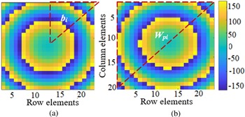
Comparing the corresponding phase compensation values with the phase curves obtained at Ku and K band resonant frequencies, a 24 × 24 cm2 RA is developed on the Rogers RT5870 substrate. As described in the previous section, a 2 mm thick air layer separates the substrate from the ground. Due to the symmetricity in the phase distribution, 78 different sizes of circular rings as shown in Fig. 7(a) are distributed over the substrate. Since the K band elements are placed off-centric with the source, their symmetricity in phase distribution varies as shown in Fig. 7(b). Hence 276 different sizes of Malta cross are distributed over the substrate for K band operation. This arrangement of integrated elements for dual-band operation avoids the optimization of the unit cell for achieving phase matching at the resonant frequencies.
Phase compensation matrix for 23 × 23 reflectarray (a) Co-centric Ku band elements, (b) Offset placed K band elements.
Note: bi, W pi – Varying circular ring and Malta cross sizes

Experimental analysis
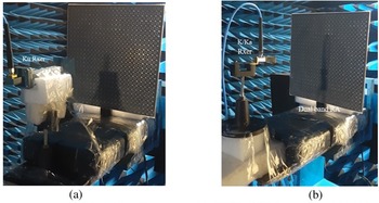
The designed RA is fabricated using the conventional photolithography process. Figure 8 depicts the measurement setup of the fabricated prototype. The fabricated RA is placed in an anechoic chamber of size 7 × 3 × 3 m. The pyramidal horn antenna used as the transmitting source is located at the far field distance co-centric with the RA. The source produces a directional beam within a frequency range of 800 to 1800 MHz. The dimensions of the pyramidal horn are a flare length of 54 mm and a waveguide aperture of size 20 mm × 10 mm. The peak gain of the horn is 17.4 dBi at 12 GHz and the beam width is 22°.
The measurement setup of the fabricated prototype with (a) Ku band receiver, (b) K/Ka receiver.

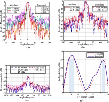
The Ku band performance of the RA is measured by placing a Ku 5041 model pyramidal receiving horn at the focal distance of 19.3 cm from the prototype. At the same distance, the Ku horn is replaced by a K band receiving horn to measure the performance of the RA within the K band operating range. Similarly, the source is replaced by an 18 to 40 GHz K/Ka pyramidal horn which provides 15.5 dB gain at 22 GHz with 22° beamwidth. The flare length of the horn is 20.5 cm and the aperture size of its waveguide is 20 × 11 mm. The radiation pattern at different frequencies over the operating range in both bands is measured. As shown in Figs 9(a) and 9(b), the simulated and measured patterns are plotted at different frequencies. The relative magnitude of the simulated pattern is 28.4 and 27.1 dB at 14.25 and 22.5 GHz respectively.
Simulated and measured radiation pattern for different frequencies in (a) Ku band (b) K band, and (c) measured cross-polarization at different frequencies, (d) Gain versus frequency plot.

The simulated SLL at these frequencies is less than −22 and −12 dB respectively. The increased value of SLL at the K band frequency is due to the offset alignment of the K band elements and the resulting phase error. Similarly, the cross-polarization levels observed at these frequencies are less than −32.2 and −30 dB respectively. The measured radiation pattern magnitudes are 28 and 26 dB at the Ku and K band resonant frequencies respectively. The beam width of the measured pattern is 6.5 and 7.1° at 14.25 and 22.5 GHz respectively. The measured SLL and the cross-polarization values are less than −21/−11 dB and −31/−28 dB respectively at both frequencies.
Since the substrate thickness is just 0.254 mm, the arrangement of a 2 mm air gap between the substrate and ground and the alignment of the prototype in the measurement setup, causes unavoidable phase errors resulting in the deviation of the measured values from the simulated results. The cross-polarization levels at different frequencies in both bands are presented in Fig. 9(c). The measured and simulated gain of the RA calculated from the pattern magnitudes using the Friss transmission formula is plotted against the operating range of frequencies as shown in Fig. 9(d). The 529 Ku band elements and the 529 K band elements offer a simulated peak gain of 28.62 dBi at 14.25 GHz and 26.92 dBi at 22.5 GHz. The corresponding measured values are 28 and 26.4 dBi respectively. Though an equal number of elements are utilized for the dual resonance operation, the gain offered by the K band elements is slightly lesser than the Ku gain because of the phase error introduced due to their offset alignment with respect to the source. Due to the fabrication errors and the misalignment error during measurement, the measured gain is slightly lesser than the simulated results. The concentric circular rings offer a 1 dB gain bandwidth of 9.8% (13.5–14.9 GHz) at the Ku band and the modified Malta cross offers a bandwidth of 3.5% (22.3–23.1 GHz). Though the percentage bandwidth is less, it covers the entire Ku band uplink frequency range required for fixed satellite services and the K band range needed for earth exploration satellites. The roll-off rate between the two bands of operation is high providing good isolation between the bands. The aperture efficiency, A e of the proposed antenna with gain in dB is calculated as

where A p is the physical aperture of the antenna and f is the resonant frequency. Therefore, the measured aperture efficiency is 38.65% at 14.25 GHz and 10.72% at 22.5 GHz. Due to the non-uniformity in the thin substrate and the thin airgap maintained between the substrate and the ground causes much reduced efficiency in the K band. To attain a better efficiency, the arrangement of the elements is reversed compared to the proposed design and simulated. The K band elements are arranged co-centric with horn and the Ku band elements are placed off-centered in the alternate design. The simulated gain obtained from this design is 29.5 dBi at 22 GHz and 27.8 dBi at 14 GHz. The corresponding calculated aperture efficiency is 38.24% at 14 GHz and 22.9% at 22 GHz. A comparison of the measured performance characteristics and the physical aspects of the proposed dual-band RA with other works discussed in the literature is reported in Table 2. Based on the comparison the following inferences are made:
1) The design of the dual resonant elements in [Reference Su, Yi and Wu3, Reference Zhu, Yang, Mcgloin, Liao and Xue8, Reference Hamzavi-Zarghani and Atlasbaf10] and [Reference Saravanan and Rangachar19] requires the matching of phase response obtained at the resonant frequencies through complex optimization procedures. The proposed RA uses integrated elements with different phase responses. Hence optimization of the unit cell is not required.
2) The maximum reduction in gain in the frequencies between the bands of dual resonance in the proposed RA is 6 dB. This value is 3 dB larger than [Reference Zhu, Yang, Mcgloin, Liao and Xue8], and 4 dB larger than [Reference Hamzavi-Zarghani and Atlasbaf10].
3) The gain offered by the proposed RA is at least 3 dB more than the gain reported in [Reference Zhu, Yang, Mcgloin, Liao and Xue8] and 5 dB larger than that in [Reference Hamzavi-Zarghani and Atlasbaf10]. The gain reported in [Reference Saravanan and Rangachar19] is much larger because of the utilization of the sub-reflector.
4) Within the reduced aperture size, nearly 400 more elements are accommodated in the proposed RA compared to the RA described in [Reference Zhu, Yang, Mcgloin, Liao and Xue8] and [Reference Saravanan and Rangachar19].
5) The cross-polarization level of the proposed RA is at least 1 dB less than [Reference Hamzavi-Zarghani and Atlasbaf10] and [Reference Saravanan and Rangachar19].
6) The SLL value of the RA designed with co-centric elements is 5 dB less than those reported in [Reference Su, Yi and Wu3, Reference Hamzavi-Zarghani and Atlasbaf10] and [Reference Saravanan and Rangachar19]. Even the SLL value of the off-centered elements is 1 dB less than [Reference Su, Yi and Wu3].
Comparison of the proposed RA with previous works

BW, Bandwidth; NR, Not reported in the paper
Hence the enhanced dual-band performance of the proposed RA is more useful for fixed satellite services and the all-weather, day and night, global observations of the earth and its atmosphere.
Conclusion
A 23 × 23 dual-band reflectarray with enhanced radiation characteristics is fabricated on a 0.254 mm thick Rogers RT5870 substrate. 529 modified Malta cross elements are interleaved between the 529 circular concentric rings to produce dual resonance at K and Ku band frequencies respectively. The phase response of both elements is individually obtained using two independent parameters enabling reduced mutual coupling between the integrated elements. The co-centric arrangement of the circular rings offers a measured peak gain of 28 dBi at 14.25 GHz and an increased SLL of −21 dB. The cross-polarization level in 13.5–14. 9 GHz range of frequencies is less than −30 dB. The off-centered arrangement of the Malta cross elements offers 26.4 dBi measured peak gain with −11 dB SLL at 22.5 GHz. Since the K band elements are offset from the source, the SLL is more in the K band frequency range, 22.3–23.1 GHz. Due to the flexible nature of the thin substrate, its alignment in the measurement setup along with the 2 mm air gap becomes complex. This complexity results in the reduction of measured performance characteristics. The proposed dual-band RA best suits in fixed satellite services and earth exploration satellites.
Acknowledgements
This work is supported by DST SERB under Core Research Grant (EMR/2017/001521).
Conflict of interest
The authors report no conflict of interest.
 Kavitha Narayanasamy received her BE degree from Bharathiar University, Coimbatore in the year 2002. She received her ME degree from Anna University, Chennai in the year 2008. She has 12 years of teaching experience in reputed institutions around Chennai. She is currently undergoing her Ph.D. degree at Anna University, Chennai. She is a research scholar in the Department of Electronics and Communication Engineering, SSN College of Engineering, Chennai. Her research interests are Antennas, Electromagnetics, Communication engineering, and signal processing. She is a reviewer of IET Microwaves, Antennas & Propagation.
 Gulam Nabi Alsath Mohammed received his BE, ME, and Ph.D. degrees from Anna University Chennai in the years 2009, 2012, and 2015, respectively. He is currently serving as an Associate Professor in the Department of Electronics and Communication Engineering, SSN College of Engineering, Chennai, India. His research interests include Microwave Components and Circuits, Antenna Engineering, Signal integrity Analysis, and Solutions to EMI problems. To his credit, he has filed 12 patents and published several research articles on antennas and microwave components in leading International Journals. He has also presented and published his research papers in the proceedings of International and National conferences. He is currently serving as an Associate Editor in IET Microwaves Antennas and Propagation.
 Kirubaveni Savarimuthu obtained her BE and ME degrees from Anna University, Chennai. She currently serves as an Associate Professor in the Department of Electronics and Communication Engineering, Sri Sivasubramaniya Nadar College of Engineering. She has 9 years of teaching and research experience. Her research interests include MEMS and NEMS device design and VLSI design. She is currently involved in the growth of ZnO nanorods for piezoelectric energy harvester and gas sensor applications. She is an active life member in IETE.