1. Introduction
The employments of swimming robots for underwater applications have been widely increased in recent years due to the need of using them in different situations in which human intervention is either dangerous or prohibited. Hence the importance of using underwater swimming robots as an alternative to human use [Reference Zhang, Ennasr, Litchman and Tan1].
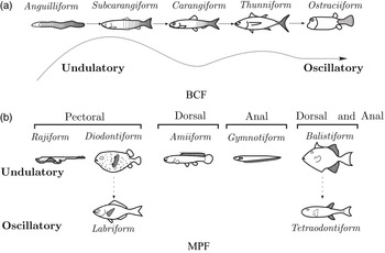
Before designing an underwater robot, there are several studies and influencing factors that must be considered in advance. For a successful design, it is necessary to imitate creatures that live underwater and inspire their swimming methods [Reference Park, Huh, Park and Cho2, Reference Ebrahimi and Abbaspour3]. Basically, there are two methods of swimming that fish use while swimming and maneuvering underwater. Depending on the main propulsors used during swimming underwater, fish either use body/caudal fin (BCF) or median/paired fin (MPF) [Reference Su, Yu, Tan and Zhang4, Reference Mihalitsis and Bellwood5]. Furthermore, according to the motion generated from the fin type, they can be classified into the undulatory-motion type and the oscillatory-motion type [Reference Sitorus, Nazaruddin, Leksono and Budiyono6] as shown in Fig. 1. Different kinds of fish use different fins as locomotors. Fins can be defined as: dorsal fin, pelvic fin, caudal fin, anal fin and paired pectoral fins. Physically, there is no such fish that uses these fins at the same time, most of them use one of these as the main locomotor or it can use a combination of two or more fins. The fin’s functionality is based on motion type of fish and its circumstances. In the BCF of undulatory-motion type, the motion created resembles a wave structure produced from fish head to its tail, for example, Carangiform and Subcarangiform modes. Carangiform locomotion requires undulation motion of the last one-third portion of the fish body whereas Subcarangiform locomotion requires undulation of the posterior half of the body of the swimmers which provides the thrust required for forwarding locomotion. For oscillatory-motion type, the movement is created by turning the body or caudal fin to propel the fish, for example, Thunniform and Ostraciiform mode. In Thunniform locomotion, only the posterior 10% of the fish body oscillates which includes the narrow peduncle and the caudal fin, whereas in Ostraciiform mode, the rigid caudal fin oscillates providing the required propulsive force [Reference Raj and Thakur7].
Swimming methods in fish.

The other movement method is the MPF undulatory like Gymnotiform, Amiform, and Balistiform. At this mode, the fish uses dorsal and anal fins in providing thrust, whereas for MPF oscillatory motion, including Labriform, the fish use pectoral fins in generating thrust, and in Tetadntiform, it use dorsal and anal fins. Another type of MPF that combines both undulatory and oscillatory locomotion is known as Rajiform [Reference Raj and Thakur7, Reference Salazar, Campos, Fuentes and Abdelkefi8].
About 15% of the fish depends on MPF modes as the main propulsion mechanism, while there are very large numbers based on BCF modes for propulsion and use MPF modes for stabilization and maneuvering purposes [Reference Popovic9]. These different modes used in swimming are used in developing various designs for underwater swimming robots with the excellence of being high maneuverable, approximately real and efficient [Reference Ren, Xu, Yang and Yan10]. There is a very large and complex interaction between the shape of a fish, its fins, and the medium in which it swims, which makes the robot design, development, and control an important challenge. Swimming robots can generate thrust in multiple ways. It can use caudal fin (tail fin) as in refs. [Reference Castaño and Tan11–Reference Aparicio-García, Naula Duchi, Garza-Castañón, Vargas-Martínez, Martínez-López and Minchala-Ávila15], pectoral fins as in refs. [Reference Pham, Nguyen, Lee and Vo16–Reference Behbahani and Tan19], or using both as in ref. [Reference Zhong, Li and Du20]. During the previous epochs, the importance of pectoral fins in the design of underwater swimming robots was carefully studied. In most of these researches, researchers have discussed the importance of pectoral fins in the maneuverability and stability of a robotic fish. Morphology, kinematics, and hydrodynamics have gained the largest portion in the studies in a form of analytical aspects as in refs. [Reference Coral, Rossi, Curet and Castro21, Reference Zhao, Ming and Shimojo22] and computational fluid dynamics (CFD) aspects as in ref. [Reference Pfeil, Katzer, Kanan, Mersch, Zimmermann, Kaliske and Gerlach23]. In ref. [Reference Behbahani and Tan18], the dynamical model of a robotic fish that is propelled by a pair of flat flexible pectoral fins based on Labriform mode swimming mechanism has been derived, and a pair of pectoral fins with different flexibilities were tested. Although a caudal fin is found in the design of the prototype, its effect has been neglected. Cownose-ray robot is designed by researchers in refs. [Reference Cai, Bi, Li, Hildre and Zhang24, Reference Behbahani, Wang and Tan25], a cownose-ray fish uses a pair of pectoral fins during its movement, and the researchers aimed to develop a robotic fish inspired by a cownose-ray fish. The thrust can be generated by a combination of oscillating and chordwise twisting motions of the pectoral fins. Authors presented the structural design with a control mechanism for the proposed design supported by number of experiments. Although they showed the effectiveness of the designed fish-like robot in maneuvering and producing higher swimming speed by oscillating and chordwise twisting of the fins only, they did not highlight the span-wise motion of the propulsion performance.
Despite a large number of studies over a few past years about swimming robots that are propelled by different sizes and shapes of pectoral fins, the effect of the concave-shaped pectoral fin in rowing motion of Labriform mode has not been investigated yet such a shape would help largely in producing a large amount of thrust force when the fins start pushing toward the backward of the body while minimizing the drag force to a minimum when the fins return back to their initial positions.
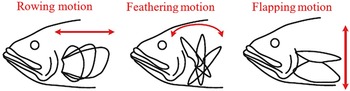
Three types of pectoral fin motions.

This work presents a novel design in the field of swimming robots based on the rowing motion of Labriform swimming mode. At this mode, the robot depends only on a pair of pectoral fins. The suggested design of these fins are concave. The objective of such a design is to improve the swimming velocity in comparison with other ones recorded in the literature. This can be achieved in two sections:
-
1. Examining the variation in speed between power and recovery strokes. The key point is to obtain the highest thrust during the power stroke while maintaining a minimum drag during the recovery stroke.
-
2. Proposing a design for the robot’s body so that the water resistance is minimal and controlling its motion through a Proportional-Integral-Derivative (PID) controller.
Then the efficiency of the designed robot is examined in terms of some dimensionless numbers like Reynolds number
 $(Re)$
, Strouhal number
 $(St)$
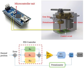
, and Amplitude to Length ratio
 $(A/L)$
. The obtained results are compared to the biological fish ranges to examine its performance.
The rest of this paper is organized as follows. Section 2 deals with the complete design of the swimming robot. Section 3 gives the linear and angular velocities transformations. The complete rigid body dynamics is provided in Section 4, while Section 5 provides a controlling method with a PID controller to improve the performance of the designed robot. Section 6 shows the parameters calculation, while Section 7 demonstrates the simulated and experimented results, and finally Section 8 concludes this work.
2. Swimming robot design
This section describes the complete design and hydrodynamic forces analysis of the swimming robot, which basically consists of two parts: 1. Pectoral fins part, 2. Body part.
2.1. Pectoral fins part
In Labriform swimming mechanism, thrust generation is accomplished by oscillating movements of pectoral fins, in which three kinds are identified in this mode as in ref. [Reference Sitorus, Nazaruddin, Leksono and Budiyono6] as shown in Fig. 2.
-
1. Rowing motion which is considered as a drag-based motion.
-
2. Flapping motion, considered as lift-based motion.
-
3. Feathering motion, which is a combination of rowing and flapping motions.
At small value speeds, drag based are usually more efficient when the flow of chordwise fin is small while they are more likely to be efficient at larger speeds in lift-based movement. Rowing is a drag-based type motion that generates thrust forces by oscillating the fins back and forth. Whereas flapping is a lift-based type of motion that generates thrust forces by up and down motions of the fin. A combination between these two motions represents the feathering fin. Pectoral fins provide a significant function in the swimming maneuvering capability and stability of real fish when generating thrust at drag based of rowing motion [Reference Sitorus, Nazaruddin, Leksono and Budiyono6, Reference Raj and Thakur7].
The resistance of water against the robot’s movement is known as the hydrodynamic force. This hydrodynamic force can be considered as a function of a robot’s motion parameter. When an object moves in the water, a portion of the water moves within the movement of the body. This moving water forms an additional body mass in addition to the original body’s mass [Reference Behbahani and Tan18, Reference Behbahani, Wang and Tan25]. In this work, the suggested design of the robot comes with a concave pectoral fins. Fin motion can be divided into two phases, defined as power and recovery strokes. At the beginning, the designed joints are positioned in a manner such that they make an angle between the base of the fin and the lateral axis of the body. During the power stroke, the fins move toward the back of the body within a velocity
 $V_{Fin(power).}$
In the recovery stroke, the fins returned back to their initial positions within a velocity
 $V_{Fin(recovery).}$
The time consumed by the fins to complete the power stroke is shorter than the time required during the recovery stroke. This way, the variation in the time between the two strokes defines a velocity of the fins at each stroke which is defined as
 $R_{F}=V_{Fin(power)}/V_{Fin(recovery).}$
The goal is to achieve the highest
 $R_{F}$
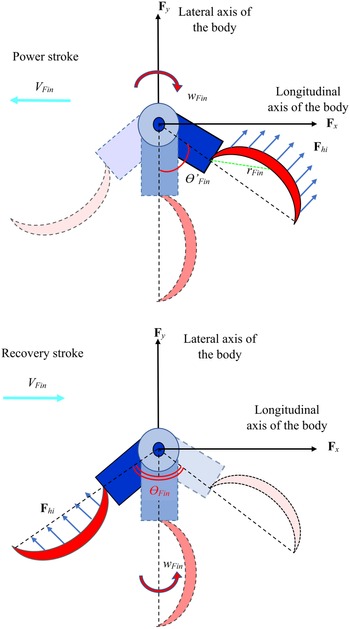
that produces a maximum thrust at power stroke while maintaining a minimum drag during recovery stroke as shown in Fig. 3.
Pectoral fin motion during different two strokes.

The blue arrows represent the reaction forces
 $F_{hi}$
generated as the fin oscillates back and forth, due to fin shape, where the subscript i represents the generated hydrodynamic forces at
 $x_{b}, y_{b}$
, and
 $z_{b}$
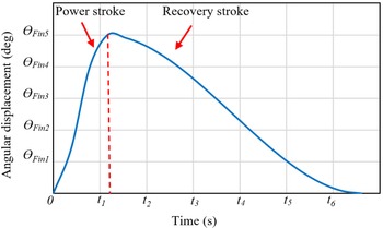
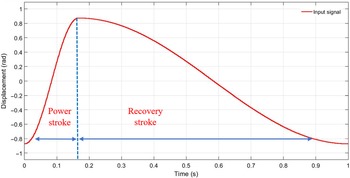
directions, respectively. These forces should be at maximum value along the power stroke and minimum value along the recovery stroke; this way the total thrust will be generated. Figure 4 demonstrates the motion input signal during the power and recovery stroke periods. However, the starting angle (
 $\theta _{Fin}^{'}$
) that lies between the fin base and the lateral axis of the body is also a parameter that affects the hydrodynamic force generation. The pectoral fins are placed in an angular position (
 $\theta _{Fin}(t)$
) such that [Reference Ma, Cai, Wang, Bi and Gong26–Reference Naser and Rashid28]:
 \begin{equation} \theta _{Fin} (t)=(A/2)-(A/2)\cos w_{f} t \end{equation}
where
 $\theta _{Fin}(t)$
represents the instantaneous angular position of the base of the fin,
 $A$
is the amplitude of the wave generated by the fin, and
 $w_{f}$
is the angular frequency which can be given as
 $w_{f} = 2\pi f$
[Reference Naser and Rashid29].
Angular position during power and recovery strokes.

The main goal, at this stage, is to determine the hydrodynamic forces applied to the pectoral fin while moving toward or backward within different fin beat angles. In order to get net thrust, the following fact is hold [Reference Ma, Cai, Wang, Bi and Gong26]:
 \begin{equation} Net_{Thrust}=\sum _{\theta _{Fin}}^{-\theta _{Fin}}Thrust-\sum _{-\theta _{Fin}}^{\theta _{Fin}}Drag \end{equation}
where the hydrodynamic forces at each angle of rotation are calculated and added to the previous angle in a step of
 $10^{\circ}$
until completing one cycle. It is noteworthy that the sign (
 $-$
) before the angle indicates the recovery stroke side, whereas the unsigned angle refers to the starting angle at the power stroke.
In order to swim at a constant speed, the total hydrodynamics (including drag/lift forces and momentums) acting on a fish should be balanced according to momentum conservation principle. Different parameters that determine the momentum exchange like Reynolds number, reduced frequency, and overall geometrical shape. The value of Reynolds number
 $(Re)$
is represented by the ratio of the inertial forces to the viscous forces as given bellow [Reference Rashid and Rashid30, Reference Ngo and McHenry31]:
 \begin{equation} Re=\frac{LU}{\lambda } \end{equation}
where
 $L$
is the length of the swimming fish,
 $U$
is the swimming velocity of the fish, and
 $\lambda$
is water kinematic viscosity. Generally,
 $Re$
in an adult fish, where inertial forces prevail over the viscous forces which are neglected. The effective forces can be generated by the incorporation of
 $Re$
pressure, acceleration reaction, drag force, and lift force mechanisms.
On the other hand, another efficiency measure of the pectoral fin shape effect is the Aspect ratio (
 $Ar$
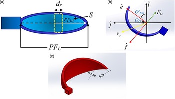
) as shown in Fig. 5 (A). This parameter represents the ratio between the squared length of the fin from base to tip to the projected surface area facing the water as follows [Reference Naser and Rashid28, Reference Gibouin, Raufaste, Bouret and Argentina32]:
Proposed pectoral fin design. (A) Front view. (B) Top view. (C) Fin dimensions by SOLIDWORKS®.

 \begin{equation} Ar=\frac{PF_{L}^{2}}{S} \end{equation}
where
 $PF_{L}$
is the pectoral fin length and
 $S$
is the projected surface area of the fin. By giving an estimate of the turning of fin shape, these measurements are directly connected to forward velocity performance and thrust generation. Tapered, high
 $Ar$
fins are generally found in the fish to generate thrust due to the lift force and keeping high velocities, whereas rounded, with low
 $Ar$
fins, are basically related with rowing motion fin to generate thrust due to the drag force and usually used at low-speed maneuverability.
Another factor that assets on swimming efficiency is Strouhal number (
 $St$
), which is for biological fish that generally lays in the range of 0.05–0.6. It is a dimensionless number that describes the oscillating flow mechanism.
 $St$
can be expressed as [Reference Gibouin, Raufaste, Bouret and Argentina32, Reference Eloy33]:
 \begin{equation} St=\frac{2f(PF_{L})\sin A}{\left | V_{b} \right |} \end{equation}
where
 $V_{b}$
is the forward body velocity. The hydrodynamic forces conducted by the proposed pectoral fins can be described as shown in Fig. 5(b). These forces can be defined as given in ref. [Reference Quinn, Lauder and Smits34]:
 \begin{align}F_{D} & = 1/2\rho \left |V_{b} \right |^{2} SC_{D} \nonumber\\[3pt]F_{L} & = 1/2\rho \left |V_{b} \right |^{2} SC_{L} \\[3pt]M_{D} & = -C_{M} w_{Fin}^{2} sgn(w_{Fin} ) \nonumber\end{align}
where
 $F_{D}, F_{L},$
and
 $M_{D}$
are the drag, lift, and momentum forces, respectively.
 $\rho$
is the water density,
 $|V_{b}|$
indicates magnitude value of the body’s linear velocity where
 $\left | V_{b}\right |=\sqrt{u^{2}+v^{2}}$
in which, surge (
 $u$
) and sway (
 $v$
) are the linear velocity components over
 $x_{b}$
and
 $y_{b}$
directions, respectively, whereas
 $C_{D}$
,
 $C_{L}$
and
 $C_{M}$
are the dimensionless drag, lift, and moment coefficients, respectively. The signum function is represented by sgn(.). The unit vectors are
 $\hat{e}$
and
 $\hat{f}$
parallel to and perpendicular to the longitudinal axis of the pectoral fin, respectively. The relationship between the body-fixed coordinate and the unit vectors of the pectoral fins can be defined by the following equation:
 \begin{align} \hat{e} & =\cos \theta \hat{i}\text{+sin} \theta \hat{j}\nonumber\\ \hat{f} & =-\sin \theta \hat{i}\text{+cos} \theta \hat{j} \end{align}
Referring to physical fish, in order to swim in a stable state, the drag force should be the same as the thrust force, and (buoyancy+lift) forces should balance the weight force. Following this manner, the fish is said to be neutrally buoyant. In swimming robots, this principle is used in balancing. To get the forward propulsion, the thrust force must overcome the drag force so that the thrust force generated from the pectoral fins is equal to the forces due to the drag plus added mass [Reference Chen35, Reference Rashid, Naser and Mjily36].
The suggested pectoral fin is designed by SOLIDWORKS® software as shown in Fig. 5(c). The specifications of these fins are listed in Table I. Each fin is attached to a pair of servo motors via very precisely designed joints such that the pectoral fin maintains the highest speed during the power stroke and the lowest speed during the recovery stroke. However, the proposed pectoral fins and joints have been printed by a 3D printer of polylactic acid (PLA) material of the density 1240
 $kg/m^{3}$
.
Pectoral fin specifications.

2.2. Body parts
This section describes a 3D design of the swimming robot. The hydrodynamic behavior, weight of the robot, biomimetic look, and waterproofness methods are the main targets that are taken under consideration with deep details. The robot’s body consists of two parts: the main body part which contains the microcontroller and other electronic units, and the robot’s head which contains a pair of waterproof servomotors. Each one is linked to a concave pectoral fin via a joint. The overall body of the robot is designed with a cross-sectional area of an elliptical form where its size gradually decreases through the longitudinal axis of the body to reduce water resistance.
2.2.1. The main body part
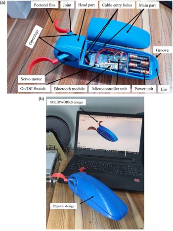
This part of the robot is designed with a hard shell of thickness 6 mm. It is designed to be symmetric about the longitudinal axis of the body. The main part of the body consists of two parts: the housing part and the lid part. Utilizing the lip and groove property of plastics in SOLIDWORKS®, the body’s lip of 2 mm thickness is built into the mating edge of the housing part, and the groove of 4 mm thickness is built into the edge of the lid as shown in Fig. 6(a). In this way, when pushing the two parts together, with the use of O-rings, the design will be sealed, waterproofed, and tightly closed.
Proposed design of swimming robot. (A) The inner components of the robot. (B) The complete 3D robot prototype.

2.2.2. The head part
To protect the internal electronics of the robot’s body from the water, the servomotors have been separated from the rest of the body, where a thin plastic plate is designed and built-in at the inner base of the head. The servomotors are fixed parallel to the longitudinal axis of the body. Fins are attached to the actuators through a small specially designed joints of 1.5 cm in length, and openings have been made on both sides of the head to facilitate the movement of the fins to the forward and backward directions during the power and recovery strokes, respectively. To provide double protection for the internal parts of the robot, the inside of the robot’s body has been coated with high-quality glue. Furthermore, for an extra protection against water, all inner electronic units are covered with NANO PROTECH coating technology spray. Motion commands are sent to the controller via the HC-06 Bluetooth module, and four 1.5V AA batteries are used to supply the robot with the required energy as shown in Fig. 6(a). The final design is given in Fig. 6(b).
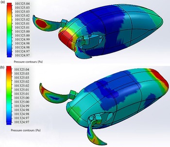
The tolerance to water conditions such as pressure (pressure
 $= \rho V_{b}^{2}/2$
) during the power and recovery periods has been confirmed. At the maximum speed of the servo motors, under a pressure of 101,325 Pa, it is noted that the maximum amount of pressure rises by a very small percentage at the frontal part of the body in the case of power stroke as shown in Fig. 7(a), when the movement of the robot is against the direction of the water flow, it reaches 101,325.04 Pa. This difference of 0.04 is considered very little and can be neglected. Likewise, the case with respect to movement during the recovery stroke when the body moves in the opposite direction to that in the power stroke, so the highest amount of pressure at the back part of the body is the same value as in power stroke motion as shown in Fig. 7(b).
Pressure distribution on the robot’s surface. (A) Power stroke. (B) Recovery stroke.

3. Velocity transformations
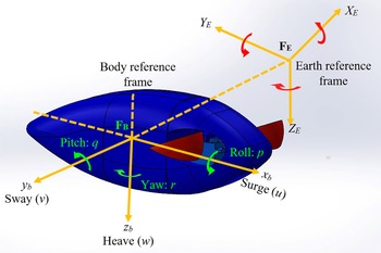
Two frames need to be defined which are the body-fixed reference frame
 $\mathbf{F_{B}}=[x_{b}y_{b}z_{b}]^T$
, in which the origin coincides with center of buoyancy and the earth reference frame
 $\mathbf{F_{E}}=[X_{E}Y_{E}Z_{E}]^T$
, where
 $T$
refers to the transpose of the matrix as shown in Fig. 8.
Body and earth reference frames.

Consider the following vectors:
 $\mathbf{\xi }=[\mathbf{\xi }_{1}^{T} \mathbf{\xi }_{2}^{T}]^{T}$
,
 $\mathbf{ \xi }_{1}=[x y z ]^{T}$
,
 $\mathbf{\xi }_{2}$
=
 $[\phi \theta \Psi ]^{T}$
, where
 $\mathbf \xi$
represents the position and orientation coordinates with respect to the earth-fixed reference frame
 $\mathbf{F_{E}}$
. The velocity vector is defined as
 $\mathbf{V}$
with linear
 $\mathbf{V}_{b1}$
and angular
 $\mathbf{V}_{b2}$
velocities, whereas the force/momentum vector are defined as
 $\mathbf{F}_{b}$
and
 $\mathbf{M}_{b}$
, respectively. These vectors can be given as follows:
 \begin{align*}\mathbf{F_{B1}}&=[x_{1} y_{1} z_{1}]^{T}, \mathbf{F_{B2}}=[x_{2} y_{2} z_{2}]^{T}, \mathbf{F_{B3}}=[x_{3} y_{3} z_{3}]^{T}\\[3pt] \mathbf{F_{b}}&=[F_{bx}F_{by}F_{bz}]^{T}, \mathbf{M_{b}}=[M_{bx} M_{by} M_{bz}]^{T},\boldsymbol{\Gamma}=[F_{b} M_{b}]^{T} \end{align*}
where
 $\boldsymbol{\Gamma }$
represents forces/moments in vector form.
 $\mathbf{V_{b1}}$
and
 $\mathbf{V_{b2}}$
are the linear velocities components and angular velocity components, respectively such that
 $u$
,
 $v$
, and
 $w_{z}$
are the surge velocity, sway velocity, and heave velocity, respectively. While
 $p$
,
 $q$
, and
 $r$
describes the roll angular velocity, pitch angular velocity, and yaw angular velocity, respectively. The robot’s body motion with respect to the earth-fixed frame is given by a velocity transformation as in ref. [Reference Fossen37]:
 \begin{equation} \dot{\xi} _{\mathbf{1}}=\mathbf{Q_{1} (\mathbf{\xi }_{2})}\mathbf{V_{b2}} \end{equation}
where
 $\mathbf{Q_{1}(\xi _{2})}$
is a transformation matrix that relates to Euler angles roll
 $\phi$
, pitch
 $\theta$
, and yaw
 $\Psi$
. In order to find
 $\mathbf{Q_{1}(\xi _{2})}$
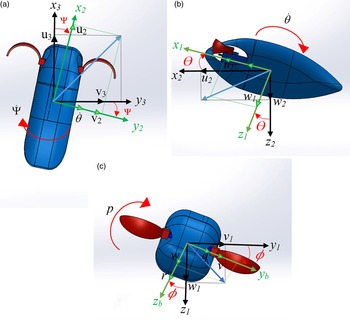
, it is described by three rotations as described below (see Fig. 9).
 $xyz$
rotational sequence showing the components of both linear velocity (
 $u, v,$
and
 $w$
) and angular velocity (
 $p, q,$
and
 $r$
). (A) Heading rotation over angle
 $\Psi$
about
 $z_{3}$
-axis where
 $w_{3}=w_{2}$
. (B) Pitch rotation over angle
 $\theta$
about
 $y_{2}$
-axis where
 $v_{1}= v_{2}$
. (C) Roll rotation over angle
 $\phi$
about
 $x_{1}$
-axis where
 $u_{1}= u_{2}$
.

Consider the following coordinates:
 $\mathbf{F_{B1}}=[x_{1} y_{1} z_{1}]^{T}$
,
 $\mathbf{F_{B2}}=[x_{2} y_{2} z_{2}]^{T}$
and
 $\mathbf{F_{B3}}=[x_{3} y_{3} z_{3}]^{T}$
. The coordinate
 $\mathbf{F_{B3}}$
is obtained by translating the earth-fixed coordinate system
 $\mathbf{F_{E}}=[X_{E} Y_{E} Z_{E}]^{T}$
parallel to itself until its origin coincides with the origin of body reference frame
 $\mathbf{F_{B}}=[x_{b} y_{b} z_{b}]^{T}$
. The resulting frame
 $\mathbf{F_{B3}}=[x_{3} y_{3} z_{3}]^{T}$
will be rotated about
 $z_{3}$
by a yaw angle
 $\Psi$
to produce another frame
 $\mathbf{F_{B2}}=[x_{2} y_{2} z_{2}]^{T}$
which will, in turn, rotated about
 $y_{2}$
-axis by a pitch angle
 $\theta$
and yielding a new reference frame
 $\mathbf{F_{B1}}=[x_{1} y_{1} z_{1}]^{T}$
. This time the resulting frame will be rotated by a roll angle
 $\phi$
about the
 $x_{1}$
-axis and producing the body coordinate reference frame
 $\mathbf{F_{B}}=[x_{b} y_{b} z_{b}]^{T}$
.
This sequence of linear velocity translations is not arbitrary, instead, it uses
 $xyz$
-convention in terms of Euler’s angles for rotation and can be expressed as in ref. [Reference Fossen37]:
 \begin{equation} \mathbf{Q_{1}(\xi _{2})}=E_{z,\Psi }^{T}E_{y,\theta }^{T}E_{x,\phi }^{T} \end{equation}
 \begin{equation} E_{x,\phi }=\begin{bmatrix} 1 &\quad 0 &\quad 0 \\[3pt] 0 &\quad \cos \phi &\quad -\sin \phi \\[3pt] 0 &\quad \sin \phi & \quad \cos \phi \end{bmatrix} \end{equation}
 \begin{equation} E_{y,\theta }=\begin{bmatrix} \cos \theta &\quad 0 &\quad \sin \theta \\[3pt] 0 & \quad 1 &\quad 0 \\[3pt] -\sin \theta &\quad 0 & \quad \cos \theta \end{bmatrix} \end{equation}
 \begin{equation} E_{z,\Psi }=\begin{bmatrix} \cos \Psi &\quad -\sin \Psi &\quad 0 \\[3pt] \sin \Psi & \quad \cos \Psi &\quad 0 \\[3pt] 0 &\quad 0 & \quad 1 \end{bmatrix} \end{equation}
The orientation of the robot’s body relative to the earth-fixed reference frame is given as
 \begin{equation} \mathbf{V_{b_{2}}}=\begin{bmatrix} \dot \phi \\[3pt] 0 \\[3pt] 0 \end{bmatrix}+E_{x,\phi }\begin{bmatrix} 0 \\[3pt] \dot \theta \\[3pt] 0 \end{bmatrix}+E_{x,\phi }E_{y,\theta }\begin{bmatrix} 0 \\[3pt] 0 \\[3pt] \dot \Psi \end{bmatrix} \end{equation}
4. Rigid body dynamics
The body’s dynamics are defined based on Kirchhoff’s relations of motion of conservation of linear momentum
 $\mathbf{M_{L}}$
and an angular momentum
 $\mathbf{M_{A}}$
in an inviscid fluid as in ref. [Reference Fossen37]:
 \begin{equation} \dot{\mathbf{M}}_{\mathbf{L}}=\mathbf{M}_{\mathbf{L}}\mathbf{xV}_{\mathbf{b}_{\mathbf{2}}}+\mathbf{F}_{\mathbf{b}} \end{equation}
 \begin{equation} \dot{\mathbf{M}}_{\mathbf{A}} = \mathbf{M}_{\mathbf{A}}\mathbf{xV}_{\mathbf{b}_{\mathbf{2}}}+\mathbf{M}_{\mathbf{L}}\mathbf{xV}_{\mathbf{b}_{\mathbf{1}}}+\mathbf{M}_{\mathbf{b}} \end{equation}
 \begin{equation} \mathbf{M_{L}=MV_{b_{1}}+D^{T}V_{b_{2}}} \end{equation}
 \begin{equation} \mathbf{M_{A}=DV_{b_{1}}+IV_{b_{2}}} \end{equation}
 $\mathbf{F_{b}}$
and
 $\mathbf{M_{b}}$
are the total forces generated and moments efforts exerted by the body at the center of buoyancy, respectively, where
 $\mathbf{M}$
can be defined as the mass matrix,
 $\mathbf{D}$
refers to Coriolis and centripetal matrix, and
 $\mathbf{I}$
is considered as the inertia matrix. These matrices represent the effect of the added mass due to fluid impact and the body’s inertia [Reference Aureli, Kopman and Porfiri38]. It is assumed that the robot is neutrally buoyant, and both centers of mass and buoyancy are of the same projection on the
 $x_{b}y_{b}$
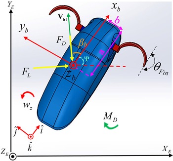
plane. The focus is on the planer motion only, that is three degrees of freedom are taken into consideration which are namely, surge, sway, and yaw, as mentioned earlier (see Fig. 10).
The free body diagram of the swimming body.

The angle of attack
 $\beta _{b}$
can be defined as the angle that the linear velocity vector
 $\mathbf{V_{b1}}$
which has a magnitude of
 $\mathbf{| V_{b1}|}=\sqrt{u^{2}+v^{2}}$
forms with the
 $x_{b}$
-axis where
 $tan(\beta _{b})=v/u$
and the direction of the robot relative to the earth frame is given by the angle
 $\Psi$
.
Furthermore, it is assumed that the robot’s body is symmetrical about
 $x_{b}z_{b}$
plane. In this case, the off-diagonal elements of the inertia matrix with respect to
 $y_{b}$
-axis will be set to zero, and by ignoring the inertial coupling between surge velocity, sway velocity, and yaw velocity, then Eqs. (14) and (15) will be reduced to the following as in refs. [Reference Behbahani and Tan18, Reference Behbahani and Tan19]:
 \begin{align}\left(M_{b} -M_{\dot{u}}{}_{{}_{a} } \right)\!\dot{u} & = \left(M_{b} -M_{\dot{v}}{}_{{}_{a} } \right)\!vr +F_{bx} \nonumber\\[3pt]\left(M_{b} -M_{\dot{v}}{}_{{}_{a} } \right)\!\dot{v} & = -\left(M_{b} -M_{\dot{u}}{}_{{}_{a} } \right)\!ur +F_{by} \\[3pt]\left(I_{z} -N_{\dot{w}_{z} } \right)\!\dot{w}_{z} & =M_{bz} \nonumber\end{align}
where
 $M_{b}$
is a robot mass,
 $I_{z}$
is the robot inertia about the
 $z_{b}$
-axis.
 $M_{\dot{u}_{a}}$
,
 $M_{\dot{v}_{a}}$
, and
 $N_{\dot{w}_{z}}$
are the effect of added mass (and or) inertia on the rigid body. In specific,
 $M_{\dot{u}_{a}}\dot{u}$
represents the hydrodynamic added mass force in the
 $x_{b}$
direction due to an acceleration
 $\dot{u}$
along the axis, in the same manner,
 $M_{\dot{v}_{a}}\dot{v}$
and
 $N_{\dot{w}_{z}}\dot{w}$
can be defined. In many practical experiments,
 $-M_{\dot{u}_{a}}$
,
 $-M_{\dot{v}_{a}}$
, and
 $-N_{\dot{r}}$
are positive numbers (see ref. [Reference Aureli, Kopman and Porfiri38]). In Eq. (18),
 $F_{bx}, F_{by}$
, and
 $M_{bz}$
are the forces in
 $x_{b}y_{b}z_{b}$
directions, respectively, and
 $M_{bx}, M_{by}$
, and
 $M_{bz}$
are the moments about
 $x_{b}, y_{b},$
and
 $z_{b}$
, respectively. The linear and angular momentum can be given as following:
 \begin{align}F_{bx} & =F_{bx_{h} } -F_{D} \cos \beta +F_{L} \sin \beta \nonumber \\[3pt]F_{by} & =F_{by_{h} } -F_{D} \sin \beta -F_{L} \cos \beta \\[3pt]M_{bz} & =M_{bz_{h} } +M_{D} \nonumber \end{align}
where
 $F_{bx_{h} }$
,
 $F_{by_{h} }$
, and
 $M_{bz_{h} }$
are the hydrodynamic forces (and/or) moments transmitted from the pectoral fins to the robotic’s body, Whereas
 $F_{bx _{h}}$
,
 $F_{by_{h} }$
and
 $M_{bz_{h} }$
are the generated hydrodynamic resistant forces and moments transferred from the pectoral fins to the proposed body of the robot. These forces are evaluated based on blade element theory as in refs. [Reference Behbahani and Tan18, Reference Naser and Rashid39, Reference Naser and Rashid40]. By dividing each fin into
 $N$
rigid elements as shown in Fig. 5(a), each element with radius of
 $dr$
of equal length
 $G$
such that
 $G=PF_{L}/N$
. Then the hydrodynamic forces at
 $G$
over pectoral fin surface area
 $S=4\pi dr_{Fin}^{2}/(360^{\circ}/\theta _{R})$
is equal to:
 \begin{equation} dF_{hi}(G)=-\frac{1}{2}\rho V_{G}^{2}C_{*}\left(4\pi dr_{Fin}^{2}/\left(360^{\circ}/\theta _{R}\right)\right)\hat{e}_{V_{G}} \end{equation}
where
 $r_{Fin}$
is the radius of each fin,
 $\theta _{R}$
is the revolving angle of each fin,
 $V_{G}$
is the velocity of element
 $G$
at time
 $t$
,
 $\hat{e}_{V_{G}}$
is a unit vector in the direction of
 $V_{G}$
, and
 $C_{*}$
is the force coefficient such that (*) represents either lift force coefficient
 $C_{L}$
or drag force coefficient
 $C_{D}$
such that
 \begin{equation} C_{*}=\left \{\begin{matrix} C_{L}=3.4 \sin\! (\theta _{G})\\[4pt] C_{D}=0.4 \cos ^{2}\!\left(2\theta _{G}\right) \end{matrix}\right. \end{equation}
where
 $\theta _{G}$
is the hydrodynamic angle of attack of element G [Reference Behbahani and Tan18, Reference Behbahani and Tan19]. The hydrodynamic forces will be found as
 \begin{equation}{ F_{hi}(t)=\int _{0}^{G}dF_{hi}(G,t)} \end{equation}
The kinematics of the robot is given as
 \begin{align}\dot{X} & = u\cos \Psi -v\sin \Psi \nonumber\\[3pt]\dot{Y} & =v\cos \Psi -u\sin \Psi \\[3pt]\dot{\Psi } & =r \nonumber\end{align}
where
 $\Psi$
is the angle between the
 $x_{b}$
-axis of the body and
 $X_{E}$
-axis of global reference frame.
Generally, the drag force is the force that is in the opposite direction to the flow and the lift force is the normal force to the flow [Reference Li and Su42]. In order to evaluate the hydrodynamic force applied by the water, the proposed model is set up as stationary, and let the water be the moving part. The servomotor oscillates back and forth by
 $\theta _{Fin}$
as shown previously in Fig. 4 based on Eq. (1).
The added masses, inertia, and body’s wetted surface area were calculated by considering the robot’s body as a prolate spheroid accelerating in the water [Reference Aureli, Kopman and Porfiri38]. The body inertia is evaluated about
 $z_{b}$
-axis as
 \begin{equation} I_{z}=\frac{1}{5}M_{b}\left(a^{2}+b^{2}\right) \end{equation}
 \begin{equation} a=\frac{L_{b}}{2} \end{equation}
 \begin{equation} b=\frac{W_{b}}{2} \end{equation}
where
 $a$
and
 $b$
are the lengths of the semi-defined axis of the swimming body, while
 $L_{b}$
and
 $W_{b}$
are body’s length and width, respectively. The effect of added masses and effect of added inertia can be find as follows:
 \begin{equation} M_{\dot{u}_{a}}=-K_{1}M_{b} \end{equation}
 \begin{equation} M_{\dot{v}_{a}}=-K_{2}M_{b} \end{equation}
 \begin{equation} N_{\dot{w}_{z}}=-K_{3}I_{z} \end{equation}
where the positive constants
 $K_{1}, K_{2},$
and
 $K_{3}$
are Lamb’s K-factors that depend only on the geometrical shape of the body and can be defined as follows:
 \begin{equation} K_{1}=\frac{\alpha ^{*}}{2-\alpha ^{*}} \end{equation}
 \begin{equation} K_{2}=\frac{\beta ^{*}}{2-\beta ^{*}} \end{equation}
 \begin{equation} K_{3}=\frac{e^{4}(\beta ^{*}-\alpha ^{*})}{(2-e^{2})[2e^{2}-(2-e^{2})(\beta ^{*}-\alpha ^{*})]} \end{equation}
where
 $\alpha ^{*}, \beta ^{*}$
, and
 $e$
can be expressed as follows:
 \begin{equation} \alpha ^{*}=\frac{2(1-e^{2})}{e^{3}}\left [ \frac{1}{2}ln\left ( \frac{1+e}{1-e} \right )-e \right ] \end{equation}
 \begin{equation} \beta ^{*}=\frac{1}{e^{2}}-\frac{1-e^{2}}{2e^{3}}ln\left ( \frac{1+e}{1-e} \right ) \end{equation}
 \begin{equation} e=\sqrt{1-\left ( \frac{b}{a} \right )^{2}} \end{equation}
System efficiency
 $\zeta$
can also be defined which is measured as the useful work divided by the total work done as follows [Reference Behbahani and Tan18]:
 \begin{align} \zeta & = W_{U}/W_{T}\nonumber\\[3pt] W_{U} & =1/2 \rho V_{b}^3 C_{D}S\\[3pt] W_{T} & =\int _{0}^{t}dF_{hi}(G,t) \nonumber\end{align}
5. Improving the performance of pectoral fins
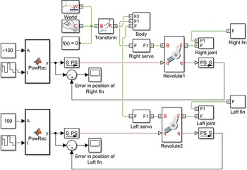
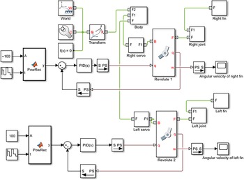
Based on the 3D CAD models designed with SOLIDWORKS® containing mass, inertias, joints, and constraints, a 3D-model of the robot is exported to MATLAB/Simulink via the Simscape add-in tool [Reference Fedak, Durovsky and Uveges43]. For multibody mechanical systems, Simscape Multibody provides a simulation environment that enables all bodies to be assembled into a physical network with connections that represent physical domains instead of using a signal-based approach. Simscape physical elements are simulated by their essential equations with original effects and actual characteristics. Figure 11 shows the Simscape construction of the proposed model. The right and left revolute joints are actuated through a Matlab function named PowRec.m which is programed to represent the servo motors motion as illustrated in Fig. 12.
Simscape model without PID controller.

Input signal.

The starting angle is set at 0.872 rad which is a translation of 50
 ${}^{\circ}$
. In order to observe the response of the system performance, the output signals of the revolute joints are connected to a scope tool to examine both the position and velocity of the right and the left fins.
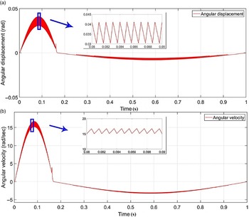
The responses of both position in Fig. 13(a) and velocity in Fig. 13(b) showed a noticeable ripple that may affect the overall performance of the system performance, so the (PID) controller has been employed to improve the performance of the system. The PID tuner GUI is a package available in Matlab. This can automatically design different controllers as required such as P, PI, PD, PID, and PID with filter, etc. The PID controller can be used in either parallel or standard forms. In order to achieve the desired performance, it can interactively adjust the controller gains after completing the system design. The objectives of PID tuning with PID tuner are to provide an acceptable performance with robust stability. The PID tuner algorithm achieves the design objectives by means of a balance between robustness and performance. PID controller can be expressed as in ref. [Reference Hernandez Beleño, Mora Gonzales, Avilés Sánchez and Ferreira44]:
 \begin{equation} E(t)=K_{p}e_{r}(t)+K_{i}\int _{0}^{t}e_{r}(t)dt+K_{D}\frac{de_{r}(t)}{dt} \end{equation}
where E(t) is the output signal of the PID,
 $e_{r}(t)$
is the difference of the expected value and the actual value,
 $K_{p}, K_{i},$
and
 $K_{d}$
are the proportional, integral, and derivative gains, respectively.
System responses without PID controller. (A) Error in position signal. (B) Output Velocity signal.

The proportional part can improve the open-loop gain and reduce the steady-state error of the system. The integration part can improve the type and strengthen the robustness of the system derivation part that can be used to improve the stability of the system and produces effective correction signal early to increase the degree of damping [Reference Su, Jiang and Shi45].
The PID tuner app, provided by Simulink® Control Design software, automatically tunes the gains of a PID controller for a single input single output system to achieve a balance between performance and robustness. Since the revolute joints were identical, only the right fin is analyzed, and the same results can be obtained for the left one. The same input signal given previously in Fig. 13 is used. The complete system design along with the PID controller is shown in Fig. 14.
Simscape model with PID controller.

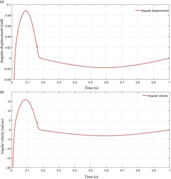
There are large improvements in the system performance in terms of position and velocity. It can be noticed that it could reach about zero after 0.18 s as shown in Fig. 15. The PID controller gains are tuned so that
 $K_{P} = 0.516, K_{I} = 203.985$
, and
 $K_{D} = - 0.00045$
. The servomotor maximum limit is translated at a maximum actuation frequency of 1.515 Hz that corresponds to 0.66 s, and the simulation time is extended to 1 s in order to be able to capture the performance trend of the whole system.
System responses with PID controller. (A) Error in position signal. (B) Output Velocity signal.

6. Parameters calculation
The parameters used throughout this work are derived either directly or empirically and are listed as shown in Table II. The added mass/inertia of the swimming robot is derived following equations (24–35) by approximating the body to a prolate spheroid shape.
Calculated parameters.

To produce a net thrust, the power to recovery stroke ratio (
 $R_{F}$
) has been varied, respectively,
 $R_{F} = 1$
for symmetrical oscillation (i.e. steady-state motion). Other ratios,
 $R_{F} = 2, 3, 4,$
and
 $5$
are used throughout this work to identify the best one in producing the maximum thrust. For
 $R_{F} = 1$
, the best starting angle is defined with the aid of CFD calculations. The maximum frequency translated from the servomotor specifications is used in determining the starting angle of oscillation at 1.5151 Hz. Equations (20–22) are adopted for the calculation of the hydrodynamic forces and coefficients.
7. Simulation and experimental results
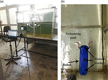
To evaluate the swimming robot’s compliance with the performance objectives, two tests have been carried out throughout this work. The first test aims to examine the robot’s ability to swim in a straight-line path. This was implemented by placing the robot in a swimming pool of (1.00 X 0.65 X 0.65) meter dimensions of (length, width, and height), respectively, as shown in Fig. 16. Evaluating of robot’s motion is achieved by placing a camera at the top view side of the robot at a distance of 0.5 m. On the other hand, the second test was designed to determine if the model could swim at variable speeds controlled by the user. Based on CFD offered by flow simulation from SOLIDWORKS®, it is able to calculate some very attractive parameters. To add a controlling mechanism and making use of the proposed PID controller method, a simple modification is done on the servomotor control circuit as shown in Fig. 17.
Swimming robot environment. (A)Isometric view. (B) Top view.

Servo motor modification.

7.1. The effect of the starting angle
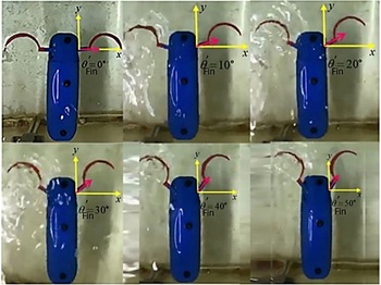
The effect of the fin beat is examined as shown in Fig. 18. The total drag force exerted by varying fin angles is presented in Fig. 19. The angle is varied from
 $\theta^{\prime}_{Fin}=0^{\circ}$
to
 $\theta^{\prime}_{Fin}=50^{\circ}$
at a step of
 $10^{\circ}$
. The obtained drag decreases linearly, where the highest drag is recorded when the fin is perpendicular to the water flow direction at
 $\theta^{\prime}_{Fin}=0^{\circ}$
. In this manner, the best angle of pectoral fin beat at power stroke is set to be
 $50^{\circ}$
. Due to the design specifications, this angle is considered as the maximum value in producing the highest thrust. All angles tests were carried out with maximum servomotor specifications of
 $1.515$
Hz of frequency and
 $0.11^{\circ}/s$
of speed.
Pectoral fin with different starting angles.

Drag force exerted by pectoral fin at different starting angles.

Forward velocity at
 $R_{F}=1$
.

Snapshots of
 $R_{F}=1$
.

7.2. Power to recovery ratio effect
In rowing motion of Labriform mode, during the power stroke, the thrust force should be at a maximum value, while in recovery stroke, the drag should be kept to a minimum. The proposed model has been tested for different power to recovery stroke ratios (
 $R_{F}$
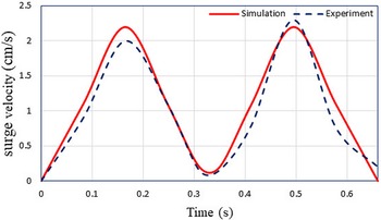
) (i.e. a ratio of 1,2,3,4, and 5). Experimental analysis for the forward velocity of the robot’s body is presented here. Fig. 20 shows the results when the power to recovery ratio
 $R_{F}=1$
. When the fins started to push the water toward the rear part of the body at power stroke, the obtained thrust is nearly the same as the drag force which is the force that is obtained when the fins returned back to their initial position at recovery stroke. For that reason, the forward velocity at
 $R_{F}=1$
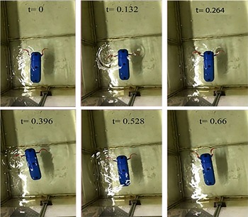
would be very small and there is no noticeable velocity gain. A snapshot of
 $R_{F}=1$
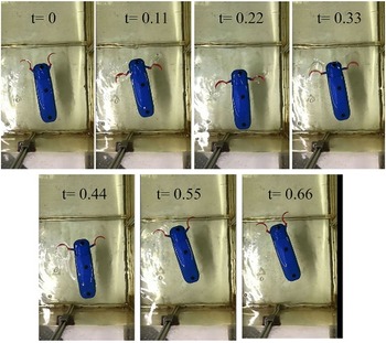
is given in Fig. 21. The power stroke cycle is completed during the first 0.33 s, while recovery stroke will start from 0.33 s to 0.66 s. In contrast, at
 $R_{F}=2$
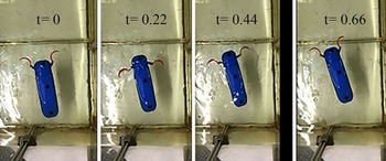
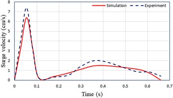
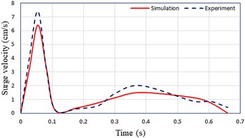
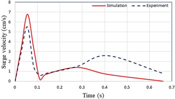
ratio, a noticeable large difference between the thrust and drag forces, which results in a forwarding velocity of about 3.8 cm/s at power and recovery stroke time, as shown in Fig. 22. Snapshots are given in Fig. 23. During the first 0.22 s, the power stroke is over and a recovery stroke is started, the gained forward velocity was interesting as expected, the experimental results are higher than free-swimming simulation results due to the large thrust generated during the power stroke cycle, and the robot was able to swim for few centimeters. Speeding up the ratio to
 $R_{F}=3$
will result in almost the highest magnitude of forwarding velocity as shown in Fig. 24. Snapshots in Fig. 25 demonstrate the swimming phases, where the power stroke started from 0 s to 0.165 s, the highest speed reached about 5.4 cm/s, while the recovery stroke will consume from 0.165 s to 0.66 s with minimum drag force.
Forward velocity at
 $R_{F}=2$
.

Snapshots of
 $R_{F}=2$
.

Forward velocity at
 $R_{F}=3$
.

Snapshots of
 $R_{F}=3$
.

Also for the ratio of
 $R_{F}=4$
, it produces an accepted value of swimming velocity as shown in Fig. 26, while Fig. 27 shows the snapshots of this ratio in which the forward velocity is about 4.2 cm/s. There is a noticeable degradation in the velocity at a ratio
 $R_{F}=5$
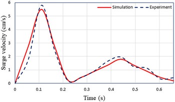
, as shown in Figs. 28 and 29. The power phase will start from 0 s and end up with 0.11 s, producing a forward velocity of about 5.8 cm/s at power stroke and 2.8 cm/s at recovery stroke.
Forward velocity at
 $R_{F}=4$
.

Snapshots of
 $R_{F}=4$
.

Comparison of swimming performance with other works.

Forward velocity at
 $R_{F}=5$
.

Snapshots of
 $R_{F}=5$
.

Although the simulation results show a positive correlation relationship between the ratio of power to recovery speed and forward velocity of the body, but the calculation of drag force showed that the drag force at power stroke time increases for the ratio of 1, 2, 4, and 5 while it is at minimum in the moderate ratio of
 $R_{F}$
=3 as shown in Fig. 24. Finally, to further clarify the effectiveness of the proposed concave shape of the pectoral fins, a collection of the swimming speed in some concerned research is reported in Table III where (BL/sec) stands for body length per second.
Figure 30 shows the total thrust generated at each ratio, it can be easily noticed that the highest thrust can be obtained at
 $R_{F}=3$
.
Hydrodynamic thrust generated at different
 $R_{F}$
.

Servomotor torque calculation.

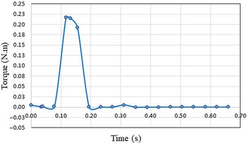
Utilizing the motion manager package, provided by SOLIDWORKS®, the required motor torque is calculated at the highest speed of
 $R_{F}=3$
and a maximum frequency of 1.515 Hz. The results showed a value of 0.228 N.m as shown in Fig. 31. This value can be translated to match approximately 3 kg cm, where a Hitec HS-5086WP waterproof digital servomotor is proposed to be used.
7.3. Performance in terms of dimensionless numbers
7.3.1. Strouhal number
The dimensionless numbers are important in the investigation of the similarity between the biomechanics and physical systems, despite all the differences in motion medium or their scale [Reference Kunes46]. Strouhal number is a dimensionless parameter that describes the tail or wing kinematics of swimming and flying animals [Reference Guerrero47]. Figure 32 shows the optimal range of Strouhal numbers of the robot with different fin oscillation frequencies at the steady-state motion of
 $R_{F}=1$
. Noting that this range is higher than the real fish range. The reason behind that is the propulsion mechanism that is used in the design of the swimming robot depends on pectoral fins only, so the total forward swimming velocity is relatively low which results in higher values of Strouhal number. The obtained results are compared with ones in the literature at (1 Hz) and the designed system showed a relatively lowest value of Strouhal number in comparison with the others as shown in Table IV. The same figure also shows the propulsion efficiency. The same figure also shows the propulsion efficiency. The total propulsive efficiency for drag-based labriform locomotion is 16
 $\%$
, while the maximum propulsive efficiency of labriform swimming can reach 31
 $\%$
for rigid rays and 36
 $\%$
for flexible rays. However, the achieved efficiency is relatively low in comparison with the mentioned fish locomotion. Thus, the improvement of the propulsive efficiency for the robot with the concave pectoral fins is a challenging issue in future work.
7.3.2. Reynolds number
Reynolds number is used to determine whether the fluid is a laminar or a turbulent flow. If Reynolds number is less than or equal to 2100, it indicates a laminar flow, and if it is greater than 4000, it indicates a turbulent flow. The higher the Reynolds number, the lesser the viscosity plays a role in the flow around the airfoil [Reference Eldredge48, Reference Hatton, Burton, Hosoi and Choset49]. Figure 33 shows the drag force generated by the concave fin for the various values of Reynolds numbers. The generated drag force is proportional to the velocity in the case of laminar flow, and it is proportional to the square of velocity at turbulent flow.
Comparison in terms of
 $St$
at 1 Hz.

Propulsive efficiency and Strouhal number in the steady swimming mode.

Starting angle of pectoral fin at different Reynolds numbers.

7.3.3. Amplitude to length ratio
Scaling parameters are of great importance in describing the dominant physics of locomotion. As mentioned earlier, efficient locomotion occurs when the value of the Strouhal (
 $St$
) number is bound to the tight range of 0.2–0.4. On the other side, another non-dimensional number that relates to fin-beat amplitude
 $A$
, the length of the robot
 $A/BL$
is bound in the range of (0.1–0.3) [Reference Saadat, Fish, Domel, Di Santo, Lauder and Haj-Hariri50]. However, the results in this study show a very close value to that range as shown in Fig. 34.
Amplitude to length ratio over different oscillation ranges.

8. Conclusions
In this paper, a swimming robot actuated by a pair of concave pectoral fins has been presented. Several simulations and practical experiments were conducted. The robot’s body has been designed with an elliptical cross-sectional area to reduce underwater pressure to a minimum. Five different power to recovery stroke ratios have been simulated and validated experimentally. The results showed that the maximum thrust obtained in the moderate ratio of
 $R_{F}=3$
. This ratio is chosen to be the best ratio since it produces the largest thrust during the power stroke and the lowest drag at recovery stroke time. Several simulations and practical experiments were validated, including: The open-loop response of both position and velocity of the fin motion showed a noticeable ripple that may affect the overall performance of the system performance, therefore a closed-loop PID controller is proposed to adjust the movement of the pectoral fins and reduce ripple in both position and velocity signals. By studying the effect of the starting angle of the fin base, where the results showed that the maximum thrust is obtained when the fins start pushing the water during the power stroke is at the
 $50^{\circ}$
. While the minimum drag is obtained at (
 $-50^{\circ}$
). This fact holds even at higher values of Reynolds number, which gives a total oscillating amplitude of
 $100^{\circ}$
. The efficiency of the proposed design is tested and compared to some real fish numbers. Strouhal number (
 $St$
) was calculated and the results showed that it is relatively far from the real extent range of the fish, due to the reliability of the proposed design in swimming on pectoral fins only, and this leads to obtaining a relatively small amount of forwarding velocity, which negatively affects the values of
 $St$
. Finally, the amplitude to body length ratio (
 $A/BL$
) has been studied and compared to the physical ranges of fish. The results showed very close results to the biological ranges especially when increasing the oscillation amplitude to
 $100^{\circ}$
.The results achieved in this model have demonstrated the effectiveness of the proposed design in achieving competing properties with what has been achieved from similar designs in the literature.
Disclosure statements
None.