1. INTRODUCTION
One challenge in assuring the safe operation of complex systems is the identification and mitigation of the potential effects of failure. As complex systems have advanced in technological complexity, an increasing source of failure is the interaction of physical and software (SW) subsystems. Traditional system design approaches focus on generating concepts that would satisfy functional and performance requirements, while satisfaction of safety requirements is determined later in the validation stage. This approach is time consuming for validation of the design and can be costly to redesign for the mitigation of a failure effect. This approach is also challenging because the different sources and types of failure for different technical subsystems and their interactions must be identified. In addition, the effect of faults as they propagate through the system must be determined.
To address these challenges, methods of safety-based system design and concept-stage failure analysis are proposed in the literature (Leveson, Reference Leveson1995; FAA, 2000; Johannessen et al., Reference Johannessen, Grante, Alminger, Eklund, Torin and Assessment2001; NASA, 2004; Stone et al., Reference Stone, Tumer and Van Wie2005; Hutcheson et al., Reference Hutcheson, McAdams and Stone2006; Jensen et al., Reference Jensen, Tumer and Kurtoglu2008; Kurtoglu & Tumer, Reference Kurtoglu and Tumer2008; Jensen et al., Reference Jensen, Tumer and Kurtoglu2009; Kurtoglu et al., Reference Kurtoglu, Tumer and Jensen2010; Mutha et al., Reference Mutha, Rodriguez and Smidts2010a, Reference Mutha, Rodriguez and Smidts2010b; Mutha & Smidts, Reference Mutha and Smidts2011). The objectives are to generate and evaluate system designs where safety and risk are addressed early in the design process. Advantages of this approach include the elimination of costly redesigns and the creation of risk-based concept selection. However, these methods face the challenge of identifying the effect of faults from within the system and faults from the interactions of different technical subsystems and their propagation paths. Despite this, the use of a more abstract representation of the system early in the design process provides an opportunity to compare the behavior of the SW and physical subsystems.
In this paper, we focus on the evaluation of a system's behavior early in the design process. Specifically, our focus is on determining the effect of potential failures and their propagation paths through three different subsystems: mechanical, communication, and SW. Traditional failure-analysis techniques involve high-fidelity component models that describe nominal and faulty behaviors. However, early in the design process, specific components and their design parameters have not been selected: the design is represented using low-fidelity abstractions of intended functionality. For this reason, to make early design trade-offs, focus must be maintained on the system functions (Kurtoglu & Tumer, Reference Kurtoglu and Tumer2008).
The system design analysis in this paper is based on functional failure identification and propagation (FFIP) and failure propagation and simulation approach (FPSA) based models (described in Sections 2 and 3, respectively). We have described FFIP and FPSA metamodels based on the meta-object family (MOF) language. The MOF standard is used to define the abstract mapping between FFIP and FPSA model elements. The FFIP metamodel is instantiated to create FFIP models. System Modeling Language (SysML), a derivative of Unified Modeling Language (UML), can be easily annotated to build FFIP models. FPSA metamodels are instantiated to create FPSA models. UML can be easily annotated to build these FPSA models. UML and SysML are both based on MOF and SysML is a derivative of UML, which facilitates seamless integration. For example, activity diagrams and component diagrams can be employed to represent FFIP's function flow and configuration flow diagrams, respectively. Further, the interface feature provided by the component diagrams (both in SysML and UML) can be annotated to facilitate fault propagation from hardware (HW) to SW and vice versa.
1.1. Contribution
In this paper we formalize the FFIP method developed for fault propagation and effects analysis of electromechanical systems (Kurtoglu & Tumer, Reference Kurtoglu and Tumer2008; Tumer & Smidts, Reference Tumer and Smidts2011).
The method is further extended to analyze systems composed of two subsystems: a physical HW subsystem and a SW subsystem that interfaces with the HW. The physical subsystem represents the electromechanical components; the SW subsystem handles the control and decision logic for achieving the functionality of the physical system.
In this paper we also specifically introduce a second technique called the FPSA for the fault-propagation analysis in the SW subsystem and present its formalization. The FFIP and the FPSA approaches are described in detail in Sections 2 and 3.
Finally, in Section 4, the paper presents an integrated approach to the failure analysis of a system that contains both SW and physical subsystems. We develop the integrated system failure analysis (ISFA) technique for this purpose and formalize ISFA. Bridging the two domains (HW and SW) is achieved by mapping classes, attributes, enumerations, and data types and by introducing new concepts (represented as metaclasses) that establish the missing links between the two domains. As a part of ISFA, a full-scale simulation algorithm is built based on the event sequence diagram (ESD) framework. The simulation procedure will allow designers to automate the fault-propagation analysis of an integrated HW–SW system.
In Section 4.5 we demonstrate the ISFA technique with a holdup tank case study. The case study demonstrates two cases of commonly occurring faults that can lead to system failure. These common faults often escape the design realm and are captured only (hopefully) during the testing phase. These cases demonstrate the power of fault-propagation analysis on an integrated system.
The ISFA technique will enable the designer to
a. proactively analyze simple domain functionality and complex cross-domain functionality;
b. understand functional and cross-functional failures;
c. identify failure-propagation paths within a particular subsystem and across both physical and SW subsystems;
d. identify which function(s) will be lost, their impact on the overall system, and safeguards/redundancies that should be added; and
e. provide a safety analyst with sufficiently detailed results so that s/he can understand the safety risk(s) (FAA, 2000).
These advantages are discussed in detail in the conclusion section (Section 5).
1.2. Related work
1.2.1. Risk and reliability analysis
Safety and reliability assessment is one of the primary activities performed during each stage of the development life cycle of a safety-critical system. Some of the standard and widely practiced techniques are failure mode and effect analysis (FMEA; see MIL-STD-1629A; Department of Defense, 1980; FAA, 2000), fault tree analysis (FTA; FAA, 2000), and probabilistic risk assessment (PRA; see NUREG/CR-2300; Nuclear Regulatory Commission, 1983). These analysis techniques help ensure high levels of system reliability and are the key contributors to risk reduction. During the early design phase, once the primary system model is available, the design analysis is performed using one of these approaches or a combination of these approaches. Based on the findings of the analysis, the system design may completely change.
FMEA is an inductive technique for systematic risk analysis of the system. During the analysis, a team of experts enumerates failure modes, their causes, and their effect for each component in the system. Further, a quantitative risk assessment is provided based on the rating scale (1–10) for severity, likelihood, and detectability. Although this is a valuable risk assessment technique at the early design stage, it is not the most effective technique for complex systems. There are inherent limitations to this approach. First, the experts manually identify the effect of fault propagation. Second, only single faults can be analyzed at a particular time. Third, FMEA does not explicitly capture component interactions. Fourth, SW FMEA has limited applicability since the SW faults, their evolution, and their impact are more complex and difficult to understand without execution of actual SW code. This paper addresses these issues by proposing integration of the HW and SW design into one unified and formalized model and a qualitative simulation of the integrated model to identify fault-propagation paths and their functional consequences.
While FMEA attempts to identify system-level consequences of a component-level fault, FTA decomposes critical, system-level failures into logical combinations of component-level failures. FTA is a deductive technique that identifies the possible root causes of an undesirable system state. FTA can potentially identify more failure causes than the single-component-oriented FMEA. FTA provides a more formal representation of fault-propagation paths between the basic events (root causes of component failure) and the top event (system failure) in the form of Boolean logic. Even though FTA is a complement to the FMEA analysis technique, FTA possesses some fundamental limitations. First, FTA is a snapshot of a system state, so there is no concept of dynamic evolution of system state. Second, the fault-propagation paths that represent component interactions are expressed using Boolean logic operators. The Boolean logic is informally constructed during the expert identification of event–consequence relationships or using other less informal approaches such as digraphs (Lapp & Powers, Reference Lapp and Powers1977) and decision tables (Lee et al., Reference Lee, Grosh, Tillman and Lie1985) or qualitative simulations (Lee et al., Reference Lee, Grosh, Tillman and Lie1985). The development of this Boolean logic becomes increasingly difficult with increasing system complexity. Third, in the case of SW systems, FTA is mostly done at the code level (Towhidnejad et al., Reference Towhidnejad, Wallace, Gallo, Goddard and Flight2003). This paper addresses these issues by integrating the faulty and nominal behavior of the component (for both HW and SW) into the design and by the dynamic identification of the fault-propagation paths and their functional consequences. The system state evolution is captured in the form of mode transitions, which are used to define the component behavior. The propagation path changes according to the change in component modes. The relationships described go beyond those that can be captured by Boolean logic operators. For example, the behavioral rules implemented as state-machine diagrams can capture a number of intermediate states and transition between the states. A fuzzy logic representation of behavioral rules provides a wide range of approximations and thus is suitable for the design evaluation.
The classical PRA (NUREG/CR-2300; Nuclear Regulatory Commission, 1983) framework utilizes multiple scenarios and event-sequencing logic models (event trees combined with fault trees) to quantify risk as the product of an event's probability and its consequence (Giarratano & Riley, Reference Giarratano and Riley1989). Labeau et al. (Reference Labeau, Smidts and Swaminathan2000) mentions that the classical PRA faces the same limitations as FTA because the representation is static in nature and building an event tree requires a risk analyst who can evaluate the complex dynamics behind the scenarios. To tackle this problem, dynamic PRA was introduced to capture the effects of time and process dynamics on the scenario and remove the limitations introduced by the static nature of classical PRA. Within the dynamic PRA framework, the semi-Markov based probabilistic dynamic equations need to be solved (Devooght & Smidts, Reference Devooght and Smidts1992). These equations are extremely complex and computationally intensive. The available SW tools for dynamic reliability assessment, including ADAPT (Catalyurec et al., Reference Catalyurec, Rutt, Metzroth, Hakobyan, Aldemir, Denning, Dunagun and Kunsman2010) and SIMPRA (Mosleh et al., Reference Mosleh, Groen, Hu, Nejad, Zhu and Piers2004), are capable of automatically generating dynamic scenarios and provide accurate results. These tools are under the development phase and are not set up to include object-oriented SW design. Thus, even though dynamic PRA is a far more sophisticated tool to analyze system reliability, it is limited in scope by application (more suitable for physical systems) and computational challenges. In contrast, integrated system failure analysis (ISFA) provides a seamless integration of object-oriented SW design into the physical system models. ISFA is a younger tool that is more suitable for HW–SW intensive systems in contrast to ADAPT and SIMPRA. ISFA is qualitative in nature and computationally less intensive, which makes it more suitable for early design stage application. Due to ISFA's formal nature and the use of recent industry standards (UML and SysML), it can potentially target a wider range of industries.
While the general methodology of the three analysis methods listed above (FMEA, FTA, and PRA) can be applied early in the design process such as with functional FMEA (Hawkins & Woollons, Reference Hawkins and Woollons1998), they pose fundamental challenges that are difficult to overcome in their respective domains.
The ISFA approach presented in this paper uses an inductive approach to assess failure (similar to FMEA). The ISFA approach is simulation based, qualitative in nature, and not limited to a single fault or domain. In addition, the fault-propagation paths and the functional consequences are the output of the analysis, unlike FTA, in which the propagation paths are predetermined. Finally, PRA methods require a well-refined system design. In this research, behavioral simulation is based on abstract, qualitative models that do not require knowledge of specific component implementation. Another notable feature of ISFA is the object-oriented design representations used for SW. Object-oriented design is a paradigm shift from sequential SW design, and UML has established itself recently as the standard language for expressing object-oriented-based SW design.
1.2.2. Representation of complex system behavior in the concept stage
The main difficulty in assessing system safety and risk during the conceptual design stage is the uncertainty of the system's behavior. Yet the representation of this behavior is an important objective in system design. Several approaches have been developed to represent complex system behavior in the conceptual design stage, but they tend to view the system either from a SW perspective or from a physical one. Our objective is to concurrently assess failures in integrated engineering systems that contain both types of systems. We therefore require a common framework to interrelate the description of behavior of both physical and SW elements.
The SW design process has undergone a rapid evolution over the past two decades, and the traditional approaches are slowly being replaced by the new object-oriented design paradigm. UML (Rumbaugh, Reference Rumbaugh, Jacobson and Booch1999; Erikson, Reference Erikson, Penker, Lyons and Fado2004) is the standard for object-oriented SW modeling and contains six structuralFootnote 1 and seven behavioralFootnote 2 views of SW systems to express SW design from high- to low-level details. The widespread application of UML has led to intensive research that extends to SW reliability and risk assessment. Existing research includes completeness, consistency, and correctness verification of the UML diagrams (Iwu & Toyn, Reference Iwu and Toyn2003); UML-based approaches to perform fault diagnosis of SW systems (Iwu & Toyn, Reference Iwu and Toyn2003); UML-based risk assessment during the early phases of development (Goseva-Popstojanova, Reference Goseva-Popstojanova, Hassan, Guedem, Abdelmoez, Nassar, Ammar and Mili2003); and the study of model transformations (Whittle & Schumann, Reference Whittle, Schumann, Ghezzi, Jazayeri and Wolf2000; Selonen et al., Reference Selonen, Koskimies and Sakkinen2001). Model transformation approaches have been extended to produce established risk assessment and failure analysis models such as Petri nets (Baresi & Pezzè, Reference Baresi, Pezzè, Agha, Cindio and Rozenberg2001) and fault trees (Towhidnejad et al., Reference Towhidnejad, Wallace, Gallo, Goddard and Flight2003). UML can be easily extended because it provides extension mechanisms such as stereotypes, constraints, and tag values (Rumbaugh et al., Reference Rumbaugh, Jacobson and Booch1999; Erikson et al., Reference Erikson, Penker, Lyons and Fado2004). Using the same representation approach, UML has been extended with SysML for the representation of physical systems (Object Management Group, 2008). SysML provides a framework for representing the interrelated behavior and structure of a system in a similar fashion to the degree of representation achieved by UML. The main additions include a representation schema for system design specification and for the physical variables of flow (energy and material).
Other modeling languages have been developed for systems that focus on physical structure but are not readily adaptable to represent the specifics of SW design. Functional modeling methods can represent system behavior at a high level of abstraction (Pahl & Beitz, Reference Pahl, Beitz and Wallace1996). Largely, research using such a functional approach has focused on the electromechanical and hydrodynamic features of the system, as can be seen in the functional ontology developed in Hirtz et al. (Reference Hirtz, Stone, Mcadams, Szykman and Wood2002). Furthermore, methods to capture the behavior, structure, and function have also been focused on the physical system representation (Umeda & Tomiyama, Reference Umeda and Tomiyama1997; Huang & Jin, Reference Huang and Jin2008; Krus & Grantham Lough, Reference Krus and Grantham Lough2009). An exception to this is the mechatronic focused “Schemebuilder” (Bracewell & Sharpe, Reference Bracewell and Sharpe1996).
Some model-based approaches have been developed to automatically produce FTA- and FMEA-style analyses by annotating the system architecture with failure information (Grunske & Han, Reference Grunske and Han2008). In the area of embedded systems design, the architecture analysis and description language (Grunske & Han, Reference Grunske and Han2008) describe the runtime nominal and failure behavior; however, the HW under consideration only handles the SW execution. Besides the model-based approaches, some researchers have employed fault-propagation graphs (such as directed graphs) to analyze component dependencies and fault propagation. Multisignal flow graphs developed by Deb et al. (Reference Deb, Pattipati, Raghavan, Shakeri and Shrestha2002) are another comprehensive methodology to model cause–effect dependencies of complex systems. Finally, in cases where physical cause–effect relationships are difficult to analytically model, statistical and probabilistic classification methods are applied (Yairi et al., Reference Yairi, Kato and Hori2001; Berenji et al., Reference Berenji, Ametha and Vengerov2003).
The ISFA method described in this paper is function oriented and thus has a conceptual design focus. It integrates qualitative reasoning with behavioral simulation to enable the computation of component interactions likely to result in functional failures. In addition, ISFA allows for the identification of both the functional failures and their propagation paths that are derived from the functional and structural topology of a system. Finally, the approach is applicable to a variety of systems and it is not constrained by a database of documented, historical failure data.
2. FFIP
The FFIP technique is an approach for evaluating and assessing the risk of functional failures during the conceptual design phase. The task of the FFIP technique is to estimate potential faults and their propagation paths under critical-event scenarios. FFIP was developed with a focus on modularity and with the intent of capturing the effect of complex system interactions (Jensen et al., Reference Jensen, Tumer and Kurtoglu2008; Kurtoglu & Tumer, Reference Kurtoglu and Tumer2008; Jensen et al., Reference Jensen, Tumer and Kurtoglu2009; Kurtoglu et al., Reference Kurtoglu, Tumer and Jensen2010). FFIP identifies the propagation and functional effect of component failures by identifying the function–component mappings from a database of generic components during the system-simulation process. The database includes qualitative, state-machine behavioral models for each generic component. These behavioral models capture both nominal and faulty behavior. During the system simulation process, different nominal and faulty behaviors are triggered. Using FFIP, various conceptual designs and their limitations are explored. In the later phases, design analysis is performed to verify and validate the system. In the field of verification and validation, the use of strict formalism rules for system representation has enabled a rapid means of verifying that a model is consistent.
In this paper, the formalization of FFIP is presented. Formalization is necessary because information of a particular domain must be consistently transferred across other domains in order to correctly analyze multidomain systems.
2.1. Formalization of FFIP
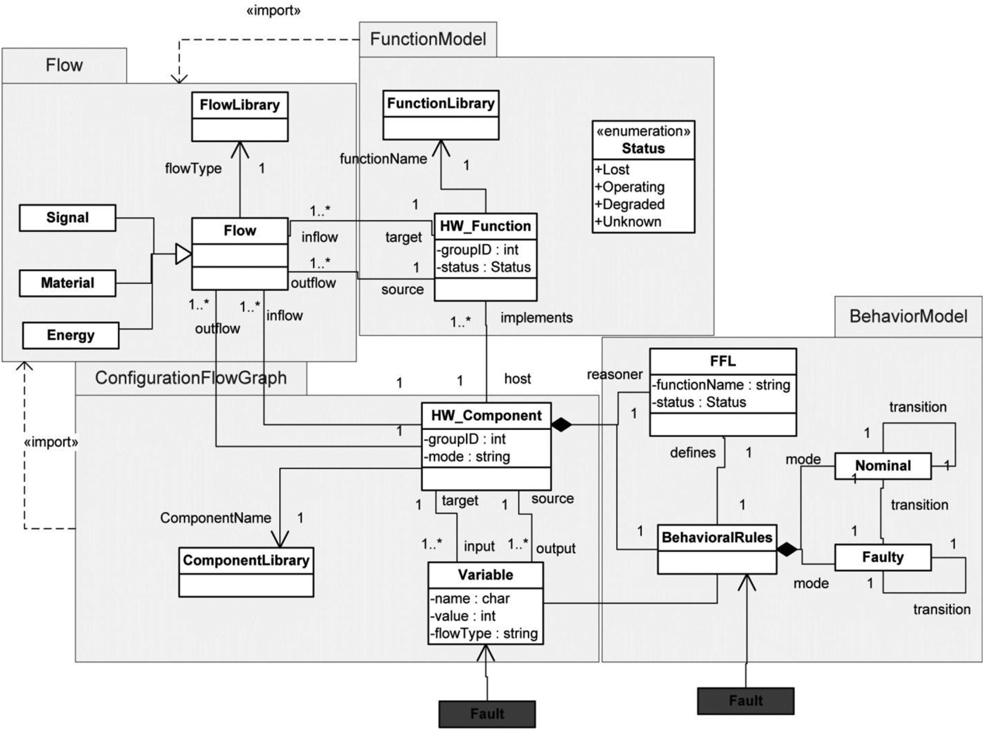
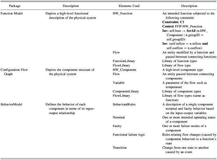
For the formalization of FFIP, the modeling elements will first be expressed using a formal language such as MOF. MOF is widely used and provides the necessary constructs for expressing the conceptual modeling element. Figure 1 shows the FFIP domain modeling elements and their relationships. The FFIP modeling approach represents a system in three different views: functional, behavioral, and in terms of components. Together, these views form the complete model of an electromechanical system. The FFIP modeling elements are divided into four packages: FunctionModel, ConfigurationFlowGraph, Flow, and BehaviorModel. The FunctionModel and ConfigurationFlowGraph import the same Flow package. Table 1 provides an overview of the different models and the modeling elements.
The functional failure identification and propagation metamodel. HW, hardware; FFL, function failure logic.

Physical system models and the modeling elements
FunctionModel is composed of functions and subfunctions, identified as the element HW_Function, and different types of Flows among functions such as Signal, Material, and Energy. The association between HW_Function and Flows indicates that the HW_Function acts on the incoming Flow and transforms it to outgoing Flow. The FunctionLibrary is a library of predefined functions that can be updated with newly discovered functions. In FFIP, “function” is viewed as the actions that the design is supposed to perform not the subjective purpose of the design (Deng, Reference Deng2002). The HW functions are selected from this function library. Similarly, the FlowLibrary is a library of predefined flow that can be updated with the newly discovered flows. Using the predefined functions and flows, and connecting them in a particular sequence, a function model is generated to achieve the actual or desired functionality of the system. Taxonomy, such as functional basis (Hirtz et al., Reference Hirtz, Stone, Mcadams, Szykman and Wood2002), can be used to standardize the naming convention of function and flow.
The component model, the configuration flow graph (CFG), is composed of HW components and subcomponents (collectively termed HW_Component); different types of flows such as Signal, Material, and Energy; and the variables depicted as Variable handled by the component. The CFG follows the functional topology. The relationship between HW_Function and HW_Component is such that one HW_Component can implement multiple HW_Function. The mapping between HW_Component and HW_Function is critical for the FFIP framework. The HW_Function acts on the input variables and transforms them into output variables. The overall component structure of the system is governed by the system functional model. CFGs and functional models are similar to directed flow graphs, where a “component” of the CFG and a “function” of the functional model act as a “node” and the “flow” acts as the “arc.” The output of one node is the input of another node. Because functions are mapped to components, the diagrams must maintain flow consistency between the functional and component views of the system. The flow in and out of a function or a group of functions is the same as the flow for the component(s) implementing the function(s). This constraint is specified by a set of “well-formedness” rules defined in the formal object constraint language. An example of this is Constraint C1 in Table 1.
The system behavioral model follows a component-oriented approach. Qualitative behavioral models are defined for each component. The component behavior is depicted as BehavioralRules that include both nominal and faulty behaviors derived from the underlying first principles and the relationship between the input and output variables. The BehavioralRules are based on representing the physics of the component interactions at a conceptual stage. This is similar to the qualitative physics (DeKleer & Brown, Reference De Kleer and Brown1984) behavioral descriptions, except that state machines are used to represent discrete nominal and faulty behaviors rather than a continuous set of equations. For example, in qualitative physics, the spring equation F = k × x describes a proportional relationship between the variables F and x. Qualitative reasoning indicates that the change in F is of the same sign and proportional in magnitude to the change in x. In this way, qualitative physics uses “landmark” values for variables instead of continuous values. For example, landmark values might be the maximum and minimum F resulting from the maximum and minimum positions of x. In this way, qualitative physics can be applied when the precise variable range is not known. While our approach to modeling behavior builds on this, in order to accomplish more precise reasoning about functional states, we have extended this to a state-based, qualitative interval model.
Our models describe discrete states of behavior using qualitative descriptions of the transformation of flows, where the flows variable is discretized into intervals. BehavioralRules are state machines composed of multiple Nominal states and multiple Faulty state definitions. A Nominal state can transition to another Nominal or Faulty state; similarly, a Faulty state can transition between other Faulty or Nominal states. The transitions are triggered by events that are environmental factors or control commands. The discrete behavioral rule approach would describe the above spring model as a few discrete states with their own behaviors such as “at rest” or “compressing and expanding.” In addition, we can include some failure states representing broken or misaligned springs. In all these states, the output force is related to the input position, so that “low” magnitude of the position flow results in “low” value for the force flow under nominal behavior states. The same holds true for other discrete levels of the input flows.
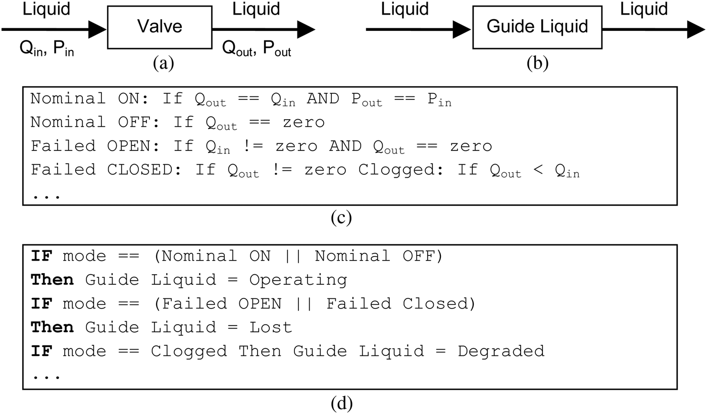
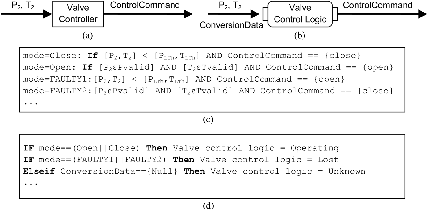
Another important element of the FFIP framework is the function failure logic (FFL). It relates the component behavior to the operating state of system functions. The FFL evaluates the input and output flow levels as defined in the component's behavioral model and relates those to the status of intended functions. This operational state is represented as the HW_Function's attribute status and is classified as Lost, Operating, or Degraded. The HW_Function.status is identified as Lost when the intended function of that component is not achieved. The HW_Function.status is said to be Operating when the intended function is achieved. Finally, the HW_Function.status is said to be Degraded when the intended function is only partially achieved. Figure 2 is a representation of a valve component, its function, its behavioral rule, and the FFL.
(a) The valve component, its input–output variables, and the flow; (b) the valve function and flow; (c) valve behavioral rules in terms of input–output relationship; and (d) valve function failure logic.
2.2. Behavioral simulation
Behavioral simulation is a discrete-time simulation integrated with the automatic functional reasoning. To simulate a fault, the fault mode transition in a component behavioral state machine is triggered. This new state defines how the component in the failed mode will change the input–output flow relationship. For example, the “clogged” state of a valve component behavioral model changes the output flow of material from nominal to zero. After a fault mode transition is triggered, the component state machines connected to that component (based on the CFG architecture) are also executed. Concurrently with the behavioral execution, the FFL evaluates the expected flow conversions. For example, the valve component is mapped to the function to regulate fluid flow. The FFL evaluates the input and output flows from the simulation and compares the expected change of implementing that function to the change observed in the simulation. The FFL then identifies the status of that specific function, as well as the status of all other functions in the model.
3. FPSA
SW fault-propagation methods are limited; they are constructed mostly from traditional risk assessment techniques (such as FTA and FMEA) developed to study physical systems. Oftentimes, they are inefficient and insufficient for complex SW analysis. These techniques are applied once the design is complete and implemented. Any design changes after risk assessment may incur large costs.
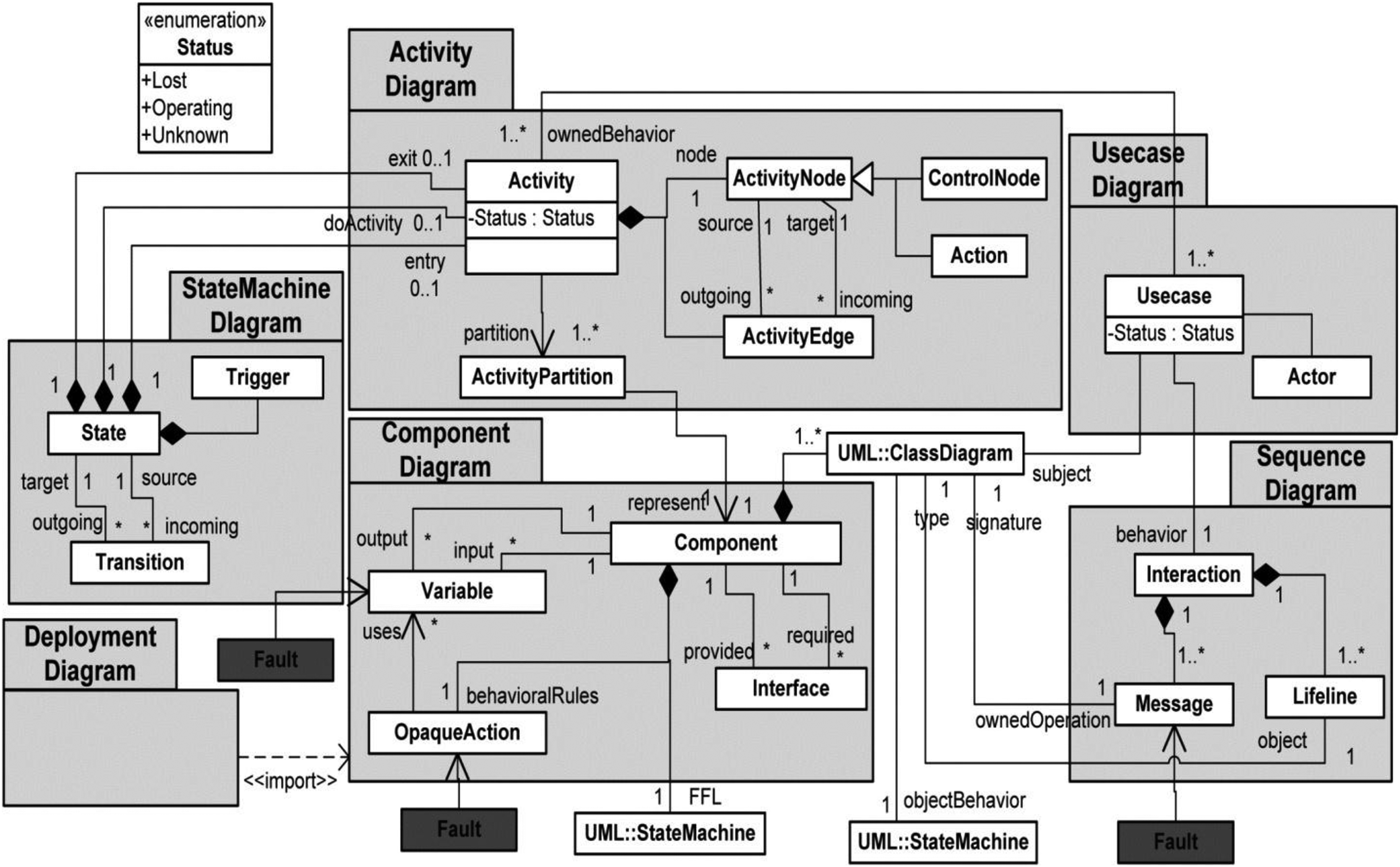
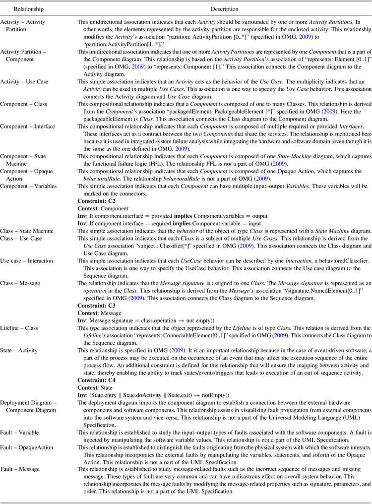
To address this lack of early design stage SW system safety analysis, we introduce a novel approach called the FPSA. The FPSA is a UML-based SW fault propagation and effects analysis method applied at the conceptual design phase. The central idea of the FPSA is the mappings between different UML diagrams. The FPSA propagates faults through various UML diagrams to determine the SW function status (Mutha et al., Reference Mutha, Rodriguez and Smidts2010a). The FPSA mapping metamodel (Fig. 3) depicts the mapping and relationships between different SW-design elements expressed in different UML diagrams. The relationships between different diagram elements are explained in detail in Table 2. The original UML metamodel of individual diagrams such as activity, state machine, and use case are preserved, while newer, more specific relationships are established between elements across the UML diagrams. These across-diagram relationships help us navigate from one diagram to another.
The failure propagation and simulation approach mapping metamodel.
FPSA specific relationships
3.1. Formalization of the FPSA
The FPSA is developed for application during the conceptual design phase where the focus is on the functional system structure and not on the implementation-level details. During the early design stage, the use case, component, and deployment diagrams assist a designer in understanding the functional requirements and SW architecture. Details such as the control logic, the behavior of the objects at runtime, and the SW structure are necessary to perform safety analysis. These details are available in the form of an activity, sequence, state machine, and class diagram. Despite duplication of information among these diagrams, each has its own unique features; therefore, it is necessary to study all of the diagrams.
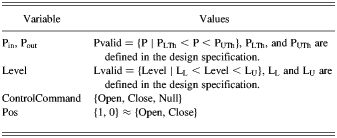
Similar to FFIP::behavioralRule and FFIP::FFL, the behavioralRule and the FFL are incorporated into the SW representation in the following way. The behavioralRule represents a novel concept introduced to study the input/output value related to failures such as value, range, type, and amount (Li et al., Reference Li, Li, Chen and Smidts2006). Behavioral rules are presented as if–then–else condition statements, where the condition is defined as the relationship between the input and output variables of a particular component. Because these rules are defined by the analyst, there is no standard format; therefore, they are implemented as Opaque Action. The behavioralRule captures the nominal and faulty operation modes of a component. These modes are defined as relationships between input and output variables. The input variables associated with the component are transformed into output variables by the activities that the component represents. An incorrect action/decision execution of the activity will result in incorrect output values that will further trigger the component's nominal or faulty modes. For example, consider a faulty execution of the decision node D1, where at P 2 = 0 (which is less than P Lth). If the condition D1 is evaluated to “false” instead of “true,” then the variable “ControlCommand” will equal “Open.” In this case, the Faulty2 mode, as shown in Figure 4c, is triggered.
(a) The software component “Valve Controller” and its input–output variables (P2 and ControlCommand), (b) the activity “valve control logic,” (c) a sample behavioral rule in terms of the relationship between input–output variables, and (d) a sample function failure logic.
The FFL is a powerful reasoning tool to determine the SW functional effect resulting from different modes defined in the behavioralRules. The FFL of each SW component is implemented as StateMachine. We can easily infer the system-level functional failure based on the results obtained from the FFL. The SW function is represented by the Activities that the component represents. Depending on the component mode, the Activity status will be Lost, Operating, or Unknown. Furthermore, the low-level functional effect can be related to the high-level failure effect based on the relationship between Activity and Use Case. An Activity may be usedIn multiple Use Cases; therefore, one Activity failure may lead to multiple Use Case failures. Furthermore, according to the standard relationship between Use Case and Actor, a use case may provide an output to multiple actors that may represent an external component such as a HW_Component. Therefore, we can conclude that failure of an Activity may lead to failure of multiple Use Cases, which in turn will affect the external component inputs. In this paper, we limit the discussion to activity failure; however, we can further extend a formal deduction of use case failure simply based on the mapping relationship between use case and activity.
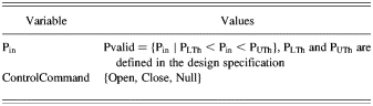
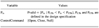
Figure 4 and Table 3 demonstrate a simple example of behavioral rules and the FFL for the SW component “Valve Controller.” In addition to input/output-value types of failure, other types can be studied. These include failure due to incorrect control logic or incorrect decisions; state-based failures; and communication-related failures such as incorrect sequence of events, object missing failures, and message missing failures.
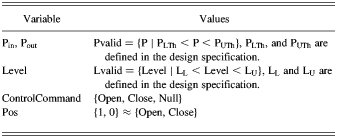
Variable and design limitations associated with software component “valve controller”
3.2. Behavioral simulation
The UML-based design provides several options for behavioral simulation. The simulation can be driven by the state machine, the activity diagram, or the sequence diagram. Of these, the simulation driven by the activity diagram fulfills our need to simulate the overall system and does so better than the other options. In addition, it is supported by the UML superstructure v2.3, which states the following:
All the behavior formalisms are potentially intra-object, if they are specified to be executed by and access only one object. However, state machines are designed specifically to model the state of a single object and respond to events arriving at that object. Activities can be used in a similar way, but also highlight input and output dependency between behaviors, which may reside in multiple objects. Interactions are potentially intra-object, but generally not designed for that purpose. (Object Management Group, 2009)
The behavior simulation of the FPSA is a simple process. Each node of the activity diagram is traversed following the control flow edges. The behavioralRules and the FFL, associated with the component represented by the activity partition, are executed at each step. This is done to evaluate the status of the SW function (i.e., activity and use case) at each node. Results are propagated to other diagrams using the mapping relationships.
4. ISFA
An integrated system is composed of HW and SW systems working together to achieve a goal or fulfill system-level functionality. Integration of two different domains demands interface matching, input/output data matching, synchronization of events, and communication in the form of correct messages and their timing. With the exception of interface matching, the other requirements are behavioral aspects handled by behavioral diagrams. The functional model of FFIP captures the functional flow of the HW system, while the activity, use case, and sequence diagrams of UML capture the functional SW aspect. Of these, only the activity diagram is capable of capturing the flow of the SW functions, handling externally triggered activities, and including elements for sending signals to external entities. Therefore, the functional model of the FFIP approach and the activity diagram of UML are integrated to study the integrated system-level function.
4.1. Formalization of ISFA
HW is integrated with SW via interfaces. An interface is a component that communicates the send/receive information between physical HW and SW systems. Various types of input–output interfaces, such as PCI buses and USBs, can perform this task. Interfaces can be complicated and may consist of a number of electronic components, such as integrated circuits, resistors, memory units, and capacitors. However, for high-level functional evaluation, the low-level component details are abstracted and the interface functions are defined based on the input/output data. In this paper, the function of an interface is abstracted as a “transaction.” Basically, this is a signal type of data object. The success or failure of an interface is observed by analyzing the properties of the transaction. Important properties of the transaction include source, target, and timing information.
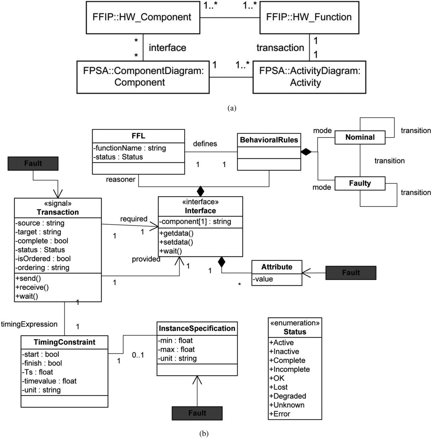
In the following discussion, the stereotype symbol, ≪ ≫, refers to a particular instance of a class. Figure 5 shows the metamodel for the ISFA analysis and elements used for integration. As shown in Figure 5a, the structural elements (the configuration flow graph components of the FFIP and the component diagram of UML) are integrated via interface, while the behavioral elements (functions of the FFIP's functional diagram and UML's activity diagram) are integrated via transaction. The associations interface and transaction are implemented as association classes and are described in Figure 5b. Each transaction is associated with an interface and with a TimingConstraint. The TimingConstraint not only imposes timing constraints on HW–SW interactions but also keeps track of time during the behavioral simulation. At the conceptual level, the HW represents the physical-system components, while the HW components specific to the SW (such as buses, storage devices, and input/output devices) are outside the scope of this paper. The attributes owned by ≪interface≫ represent the input/output data between the HW and SW components. Each class and their relationships are explained in detail in Sections 4.1.1 to 4.1.4.
(a) Integration of the functional failure identification and propagation (FFIP) and failure propagation and simulation approach (FPSA) metamodels and (b) the relationship between associations “transaction” and “interface.” FFL, function failure logic.
4.1.1. Interface
As mentioned earlier, an interface is an abstract concept that refers to a common object of interaction between two components. In the SW domain, an interface is modeled as an abstract class that contains the method signature and attributes. Its implementation details are specific to the classifier implementing the interface. Similarly, in the HW domain, an interface can be modeled as an abstract component capable of sending/receiving signals to a particular HW component. The ≪interface≫ depicted in Figure 5b can be a component's required or a provided interface (indicated by the attribute component of type “string”). For example, a “Sensor” component provides data via ≪interface≫ Isensor; therefore, ≪interface≫ Isensor becomes the provided interface of “Sensor.” An “Alarm” component requires sensor data acquired via ≪interface≫ Isensor; therefore, ≪interface≫ Isensor will be the required interface of “Alarm.” The input/output data passed between components is captured by attribute.value. The component that implements the interface acquires data by execution of the two methods that an ≪interface≫ owns. These methods are subjected to the following constraints:
Constraint: C5
Context: ≪interface≫
Inv: If ≪interface≫ .required = true and ≪interface≫ .attribute.value != null
Execute ≪interface≫ .getdata()
Execute ≪interface≫ .setdata()
Constraint: C6
Context: ≪interface≫
Inv: If ≪interface≫ .required = true and ≪interface≫. attribute.value = null
Execute ≪interface≫ .wait()
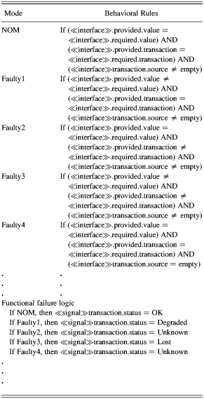
Because an interface is the communication link between the HW and SW, a malfunctioning interface can lead to failure of the complete system. To study the effect of interface faults, we apply the failure reasoning of FFIP to interface modeling. Similar to FFIP, each interface has a set of input/output-based behavioral rules and the FFL. The behavioral rules consist of nominal and faulty modes of interface; the FFL defines the functional effect in a particular mode of operation. Sample behavioral rules and the FFL are provided in Table 4.
Sample behavioral rules and functional failure logic of an interface
4.1.2. Transaction
A transaction is an instance of a signal and defines the communication details of the HW–SW interaction. Its function is to communicate that the HW function has generated the necessary data and is ready to send it, while the SW function is ready to receive the data and vice versa. Each transaction is associated with an ≪interface≫, where the provided interface will send the transaction and the required interface will receive it. The transaction is also associated with a TimingConstraint. The details of the transaction are stored in the following six attributes.
1. Source: Name of the function that initiates a transaction. The source can be either a HW_Function or a SW Activity.
2. Target: The name of the function that receives a transaction. It is subjected to Constraint C7, indicating that the target function domain is different from the source of a transaction.
Constraint: C7
Context: ≪transaction≫
Inv: If ≪transaction≫.source = Activity implies ≪transaction≫.target = HW_Function
Inv: If ≪transaction≫.source = HW_Function implies ≪transaction≫.target = Activity
3. isOrdered: Indicates that the transaction follows a particular order. The default value is “false.” The order is defined by the attribute “ordering.”
4. Ordering: Defines a sequence of transactions that should occur when the isOrdered is set to “true.”
5. Complete: A flag that indicates completion of a ≪transaction≫. It takes a Boolean value. The default value is “false.”
6. Status: Indicates the status of the transaction. The transaction status is represented using a 2 × 1 vector. The first component indicates the status of the transaction as it relates to the physical condition of the interface. The second vector component indicates the status of the transaction resulting from the dynamic execution of the HW–SW interaction. These two components of the component vector are independent. The first component of transaction status may take the values OK, Degraded, Lost, or Unknown. OK indicates the data has correctly transferred between HW and SW. Degraded indicates the data was corrupted while it was transferred between HW and SW. Lost indicates the data transfer did not take place. Unknown indicates transaction status cannot be determined based on the available input and output. The second component of the transaction status vector can take the values Active, Inactive, Complete, Incomplete, Never started, or Error. Active indicates the transaction was created. Inactive indicates the transaction was not created. Complete indicates the attribute transaction.complete is set to “true” (i.e., the transaction is complete). Incomplete indicates the transaction did not execute to completion. Never started indicates that the transaction was not allowed to start. Error indicates the execution of ISFA was faulty. The default status of the vector is (OK, Inactive). The second component is subjected to necessary conditions defined in terms of relevant TimingConstraint.start and TimingConstraint.finish states. Some of the combinations of start and finish states are unachievable.
4.1.3. TimingConstraint
In addition to ensuring completion of communication between the objects, timing is another important factor to determine the reliability and safety of a safety-critical system. Traditionally, the timing requirements are implemented by a watchdog timer. In this paper, we represent the timing requirements as TimingConstraint for each transaction. The TimingConstraint also handles the synchronization aspects of the HW–SW integration. Therefore, TimingConstraint must be specified for each transaction. If ≪transaction≫ is unable to fulfill its associated TimingConstraint, the transaction.complete flag is set to “false.” This would indicate that the communication between the objects did not complete in a timely manner. The transaction.status would then be set to “Incomplete.” TimingConstraint records logical temporal details of a transaction in the following five attributes.
1. Start: Marks the beginning of a transaction. The attribute has states: “–1” (unable to start), “0” (not started), and “1” (started). The default value is “0.”
2. Finish: Marks the end of a transaction. The attribute has states: “–1” (unable to finish), “0” (not finished), and “1” (finished). The default value is “0.”
3. Ts: Start time of the transaction.
4. Timevalue: The physical time during the execution.
5. Unit: The unit of time measurement of the system analysis; for example, millisecond, second, and hour.
The attributes of each TimingConstraint are subjected to the following constraints (C8):
Constraint: C8
Context: TimingConstraint
Inv: self.start = “1” and self.finish = “1” implies transaction.complete = true
Table 5 constitutes the second component of ≪transaction≫.status that results from the dynamic execution of the IFSA model. Boolean logic of start and finish values constitutes the interface's behavioral rules, while the “Status” constitutes the FFL. The default values of [start, finish] are [0, 0] and change dynamically during the model execution.
All possible combinations of [Start, Finish] and corresponding interpretation of Status

4.1.4. InstanceSpecification
InstanceSpecification is a class used to model additional constraints imposed by the data-transfer protocols. A computer is a discrete-time system that sends/receives data at specific instants of time to monitor/control a continuous physical process. The data-transfer process has to follow a specific communication protocol depending on the communication model selected, for example, a “polling system.” The communication model imposes additional restrictions such as when and how long a TimingConstraint on a particular transaction is valid and how often data is transferred. The InstanceSpecification class can be modified to adopt these requirements. For example, according to Dasarathy (Reference Dasarathy1985), TimingConstraint on events occurring in real-time systems are classified into types: maximum, minimum, and durational. In this paper, for demonstration purposes, we consider the following attributes of the InstanceSpecification:
1. Min: Defines the minimum time t, which must elapse before a transaction is activated.
2. Max: Defines the maximum time t, allotted for a transaction to complete.
3. Unit: The unit of time measurement of the system analysis; for example, millisecond, second, and hour.
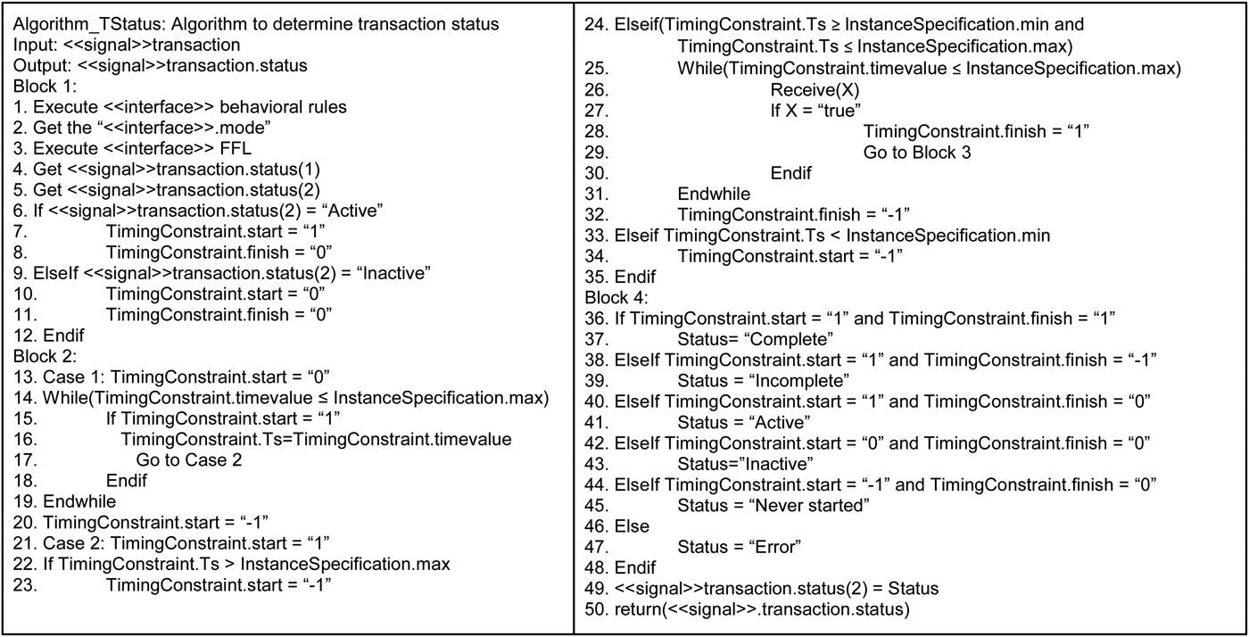
The transaction status depends on the type of data transfer algorithm selected for communication. Different communication algorithms can be modeled and inserted into the ISFA execution model to determine their system-level functional impact. An example of a simple data-transfer model is expressed in algorithm format as “Algorithm_TStatus” (Fig. 6). According to the “Algorithm_status” algorithm, data transfer by the transaction takes place within a time window of [t min, t max]. If the data are sent too early, before t min, then the data are rejected. This is indicated by the attribute ≪signal≫ transaction.start = “–1.” If the data are sent/received too late, after t max, then the data are not transferred. This is indicated by the attribute ≪signal≫ transaction.finish = “–1.” The detailed algorithm is given in Figure 6.
The Algorithm_TStatus.
4.2. ESD notation
Dynamic systems involve interactions among HW, SW, and humans. The behavior is event driven, meaning it is important to know when events such as SW changes and HW state changes occur. An occurrence of an event could lead to different system behavior. Furthermore, the sequence of events must be known to determine a particular behavior. Finally, occurrences of events also depend on time-evolving system variables, potentially affecting the dynamics of the SW.
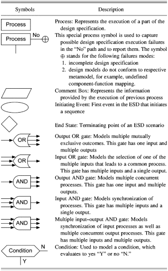
The ESD is a framework that represents sequences of events ordered in time. ESDs are similar to typical flow charts and likewise are useful in understanding the sequence of events leading to a particular behavior. They are easily constructed and facilitate modeling of conditions, concurrent processes, mutually exclusive outcomes, synchronization processes, and other highly time-dependent situations (Swaminathan & Smidts, Reference Swaminathan and Smidts1999). In this paper, we adopt elements of the ESD notation (Table 6) to execute the metamodel elements.
Event sequence diagram symbols
4.3. The ISFA execution model
The execution model of the ISFA technique is expressed using the ESD notation. The HW and SW design execute in parallel. They communicate via transactions of the related interfaces. Both the HW and the SW design execution include communication-related processes, for example, creation of a transaction and determination of the transaction status. These communication-specific processes ensure that data is transferred from one system (function) to the target system (function) in a timely manner. The execution model outputs the function statuses of the HW, SW, and Interface. These are input into the system function status identification process explained in Section 4.4.
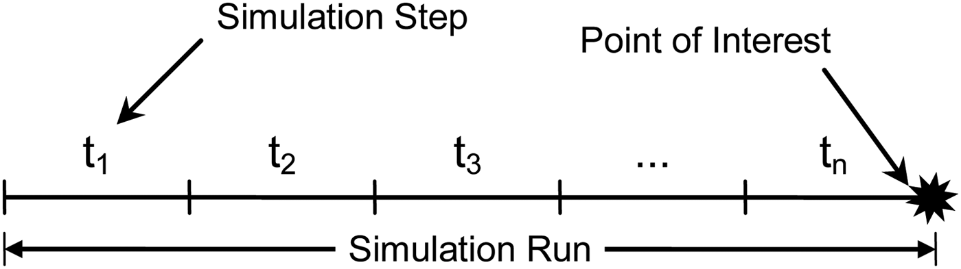
To evaluate the design, the execution model is simulated over multiple time steps. In the context of the ISFA execution model, a “simulation step” is defined as one full execution of all the processes contained in the execution model, that is, execution until the last component of the CFG and of the activity diagram. A “simulation run” is defined as a repetition of a simulation step until the point of interest (e.g., a prespecified mission time defined in multiples of the simulation step) or point of failure.
Figure 7 shows the concepts of simulation step and simulation run. For each simulation step t 1, t 2, t 3, … , t n, the clock (shown in Fig. 8) is reset. Therefore, the total time of simulation run can be calculated as t = t 1 + t 2 + t 3 + ··· + t n.
A simulation step and simulation run.
(Color online) The integrated system failure analysis execution model at time step t.
The ISFA simulation process involves a synchronized execution of the HW design and the SW design. The synchronization occurs via transaction. The HW design execution is driven by the FFIP's CFG, while the SW design execution is driven by the FPSA's activity diagram. Each execution algorithm is detailed in Figure 8 and explained below.
The start of the execution leads to the process “Initialize the system,” which sets the initial conditions of the HW, the SW, and the transaction models of the system. After initialization, two concurrent paths, p1 and p2, are created by the AND1 gate. Path p1 leads to HW design execution, while path p2 leads to SW design execution. Along each execution path transactions are created and read that ensure synchronization of the HW/SW design execution.
4.3.1. HW design execution
Path p1 leads to an OR1 gate. The multiple-input/single-output OR1 gate creates a loop, which iterates over the HW components of the CFG. OR1 leads to path p3, which points to the process “Identify the HW_Component (i),” where “i” is an index to identify a HW_Component. For each component identified, a multiple-input/single-output OR2 gate creates a loop that iterates over all the functions of the component in consideration. OR2 leads to the process “Read HW_Function (i,j),” where “j” is an index to identify a HW_Function of the i-th component. The outputs of this process (i.e., function name, inflow, and outflow information) are presented in the comment box. For each function identified, a multiple-input/single-output OR3 gate creates a loop that iterates over all the inflows of the functions. This iterative process over the inflows consists of a condition check “Is inflow (i,j,k) = ≪signal≫ transaction?” where “k” is an index to identify the inflow of the j-th function of the i-th component.
a. If the above condition is evaluated to “Y,” it means that an incoming transaction is necessary to execute the HW_Function (i,j). The transaction is created during the SW design execution, while it is read during HW design execution by the process “Read ≪signal≫ transaction.”
The process returns the detail of the corresponding transaction (i.e., target and status). Next, the condition “Is HW_Function (i,j) = transaction.target?” checks if the target of the transaction is the function being executed. If “Y,” the process “Execute Algorithm_TStatus” evaluates the transaction status. The process leads to AND3, where the path branches into two parallel paths: p4 and p5. Path p5 ends with the process “Update transaction(k).status.” Path p8 leads to a condition check “Is inflow (i,j,k) = ≪signal≫ transaction?” If “N,” it leads to a condition check “Is k > #inflow?”
b. If the above condition is evaluated to “N,” the loop continues to execute until the condition “Is k>#inflow(kmax)?” is satisfied.
Once all the inflows of the function are identified, the execution path marked as p6 leads to the process “Execute HW_Function (i,j).” This process will modify the output variable values and may cause a component mode change. Therefore, the next process, “Execute the Behavioral Rules,” is executed to identify the mode of the component. Each mode definition comprises a set of variables assembled in a mathematical equation. These variables are extracted by the subsequent process “Extract variables.” This process provides the name, value, and flow type as seen in the subsequent comment box, further leading to the AND4 gate. AND4 branches path p6 into two parallel execution paths: p7 and p8. Path p7 leads to the process “Execute FFL,” which determines the function status, and the process “Update HW_Function status” terminates this path. Path p8 leads to OR4, which iterates over all the output variables of the function being considered and checks if there is any outgoing transaction signal.
OR4 leads to the condition check “Is outflow (i, j, m) = ≪signal≫ transaction,” where “m” is the index of outflow variable.
a. If the above condition is evaluated to “Y,” it leads to AND6, which creates two parallel execution paths: p11 and p12. Path p11 increments the outflow counter and leads to OR4. Path p12 leads to the process “Create the ≪signal≫ transaction” that instantiates the necessary signal and its attributes (i.e., source, target, and status). The transaction will be read during the SW design execution. Path p12 ends with the process “Update transaction(m).status.”
b. If the above condition is evaluated to “N,” it leads to AND5, which creates two parallel paths: p9 and p10. Path p9 checks the condition “Is m > #outflow(mmax)?” and increments the outflow if the condition evaluates to “N.” Path p10 leads to a condition check “Is j > #functions(jmax)?” which checks if the index of the current function is greater than the total number of functions of the i-th component. If “Y,” then the execution process leads a condition check “Last component?” If “Y,” the last component of the CFG is reached and the execution path p1 ends. If “N,” the path leads to OR1, which iterates over the next component. If the condition “Is j > #functions(jmax)?” evaluates to “N,” then the execution process leads to OR2 and the iteration over the next function continues.
4.3.2. SW design execution
The SW design and its execution are fundamentally different from the HW design within which it operates. In an object-oriented SW design, the structural diagrams do not capture the flow of the SW execution. The flow of the SW execution is captured in the activity diagram.
The SW design execution begins with the process “Execute the main activity diagram.” The process leads to OR5, which iterates over all the activities of the main activity diagram. The output of OR5 marked as path A1 leads to the process “Read Activity (l),” which returns the name of the activity (l), which further leads to the process “Identify the component,” which returns the name of the component that surrounds Activity (l), the components inflows (nmax), outflows(pmax), where nmax and pmax are the maximum number of inflows and outflows, as shown in the subsequent comment box. This leads to OR6, which iterates over all the inflows of Activity (l). The iteration involves a condition “Is inflow(n) = ≪signal≫ transaction?”
a. If the above condition evaluates to “Y,” it leads to the process “Read ≪signal≫ transaction.”
b. If the above condition evaluates to “N,” it leads to another condition, “Is n >#inflow(nmax)?”
If “Y,” it leads to path A4. If “N,” it leads back to OR6 to evaluate the next inflow.
The process “Read ≪signal≫ transaction” returns the details of the corresponding transaction (i.e., target and status), as presented in the subsequent comment box. Next, the condition “Is Activity (l) = transaction.target?” checks if the activity being executed is the same as the activity identified during the HW design execution.
a. If the above condition is evaluated to “Y,” the process “Execute Algorithm_TStatus” evaluates the transaction status. The process leads to AND7, where the path branches into two parallel paths: A2 and A3. Path A3 ends with the process “Update transaction(n).status.” Path A2 leads back to the condition “Is n >#inflow(nmax)?”
b. If the above condition is evaluated to “N,” it leads directly to the condition “Is n > #inflow(nmax)?”
Once all the inflows of the function are identified, the execution path marked A4 leads to the process “Execute Activity (l),” which further leads to AND8. This process will modify the output variable values that may or may not cause a component mode change. The AND8 gate divides path A4 in two parallel paths: A5 and A6.
Path A5 leads to the process “Execute the Behavioral Rules” and determines the component mode, as presented in the subsequent comment box. Next, the process “Execute FFL” is executed to determine the status of the Activity (l).
Path A6 leads to the process “Extract outflow variables,” which returns the name of the variables, their values, and their flow type. The process leads to OR7, which iterates over all the outflows. During the iteration, the condition check “Is outflow(p) = ≪signal≫ transaction?” is performed.
a. If the condition evaluates to “Y,” it leads to AND9, creating two parallel executing paths: A7 and A8. Path A7 increments the outflow counter and leads to OR7 to evaluate the next outflow. Path A8 leads to the process “Create the transaction,” which creates an object of the transaction and sets the transaction (p).status = “Active,” as shown in the subsequent comment box. The path ends with the process “Update transaction(p).status.”
b. If the condition evaluates to “N,” it leads to another condition, “Is p> #outflow(pmax)?” If this condition evaluates to “N,” the next signal is considered. If this condition evaluates to “Y,” a check on the end of main activity diagram is performed. If the end of main activity diagram is reached, the execution path p2 ends. Otherwise, the next activity is read.
4.4. Evaluation of system function status
System functions are identified in the system requirements. These functions are decomposed into HW, SW, and interface functions. Determination of system function is dependent on the status of the decomposed functions. However, evaluation of system function status based on the decomposed functions status is not a matter of set theory union. A system failure can be defined in terms of critical physical variables that cross limiting conditions. These conditions, which are called “system failure criteria,” are deterministic and are predefined by the system analysts/designers. The state of the critical variables continuously changes during the ISFA design execution described in Section 4.3. The evolution of these critical variables is the result of HW_Function, Activities, and transactions. At the end of each simulation step, the state of the critical variables must be evaluated to determine if a system failure has occurred. An overview of the complete process of system function status evaluation is summarized in Figure 9.
An evaluation of the system function status. IFSA, integrated system failure analysis; HW, hardware; SW, software.
4.5. Case study
In this section, we demonstrate the application of the ISFA method using a “holdup” tank system (Fig. 10). The holdup tank in this case study is composed of an inlet valve with a position sensor, pipes, a tank with a pressure sensor, an outlet valve with a position sensor, and a SW-based computer controller. The function of the holdup tank system is to regulate the fluid flow from the tank to the output pipe while maintaining the desired water level in the tank. If the pressure is below a critical value, the output flow must be stopped and the input flow must start so that the water level is within the desired range. The input and output valves operate according to the SW-controlled logic defined in the activity diagram.
(Color online) A schematic of the holdup tank system.
The holdup tank system ensures a constant flow (say, Q) of water to a nuclear core as the heating element. In this hypothetical example, we assume that if the water supply from the holdup tank is lost for more than 5 units of time, the core may uncover, leading to an accident. As a safety measure, a backup system pumps water from a limited-capacity reservoir when the water level in the holdup tank drops below the lower threshold limit. The availability of the backup system is limited, for example, let us assume that water can be pumped for up to 5 units of time and the reservoir can be refilled every 20 units of time. Thus, the backup system availability is one for only 5 units of time and zero for the remaining 15 units of time.
In this case study, we initially describe the models that conform to the ISFA metamodel, followed by the demonstration of the ISFA simulation process (Fig. 8). The demonstration includes analysis of two different faults: a tank leak that leads to fatigue failure of the outlet valve and an incorrect SW modification in the presence of a tank leak. How these faults propagate within the ISFA models and lead to the system failure will be discussed in detail.
4.5.1. System model
The system component model is shown in Figure 11. The component model is composed of the following parts:
1. Physical component model: It is described by the FFIP::ConfigurationFlowGraph. The components include the inlet valve with a position sensor, pipes, a tank with a pressure sensor, and an outlet valve with a position sensor. The flow between the components is liquid and that between the interfaces is signal.
2. Interface model: Based on the ISFA metamodel, the ≪interface≫ are annotated as I1, I2, I3, I4, and I5 on the model. For example, ≪interface≫I1 and ≪interface≫I2 are required interfaces of SW component Sensor, while ≪interface≫I1 and ≪interface≫I2 are provided interfaces of HW components pressure and position sensors, respectively.
3. SW component model: Described by the combined UML::Deployment diagram and the UML::Component diagram. This model conforms to the additional constraints imposed by the FPSA metamodel. The SW components are ConfigurationManager, Sensor, and Valve Controller.
(Color online) An integrated system failure analysis component diagram. CFG, configuration flow graph.
Figure 12, Figure 13, Figure 14, and Figure 15 illustrate the system functional models. The three parts are the following:
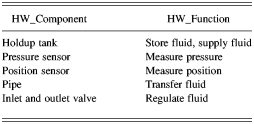
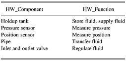
1. Physical function model: Described in Figure 12, this contains the FFIP::Functional model that conforms to the HW_Function–HW_Component mapping relationship. The relationship is explicitly tabulated in Table 7 for completeness.
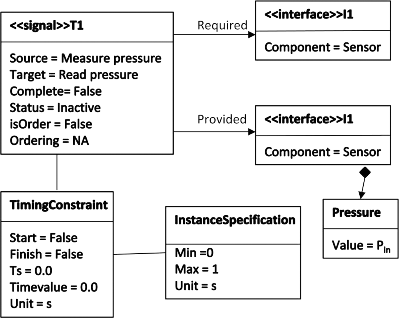
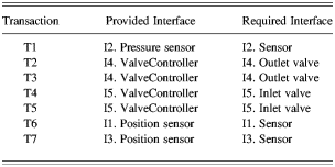
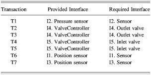
2. Transaction model: Based on the ISFA metamodel, the ≪signal≫ transactions are annotated as T1, T2, T3, and T4. Figure 15 presents the details of a sample transaction, T1. The attributes of the TimingConstraint associated with each transaction are set to default values (i.e., start = 0; finish = 0; timevalue = 0; units = s). These attributes change during the simulation process, as discussed in Section 4.2. Table 8 summarizes the transaction–interface association.
3. SW function model: Figures 13 and 14 describe the activity diagrams conforming to the additional constraints imposed by the FPSA metamodel. Figure 13 clearly presents the component–activity mapping relationship.
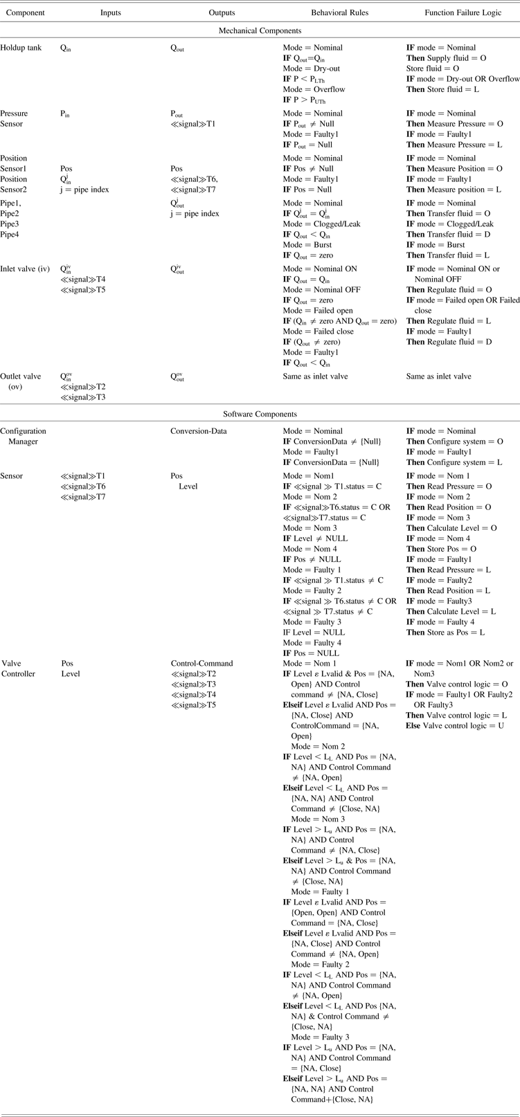
The behavioral rules and the FFL are presented in Table 9, and the variable and design limitations associated with SW component “valve controller” are provided in Table 10.
(Color online) The integrated system failure analysis functional model of the holdup tank system.
(Color online) The main activity diagram of the computer controller.
(Color online) The valve control logic of the main activity diagram.
A sample transaction instance ≪transaction≫ T1.
Mapping of hardware component to hardware function
Mapping of transaction to provided and required interfaces
Behavioral rules and function failure logic
Note: O, operating; L, lost; D, degraded; U, unknown; C, complete; NA, not applicable.
Variable and design limitations associated with software component “valve controller”
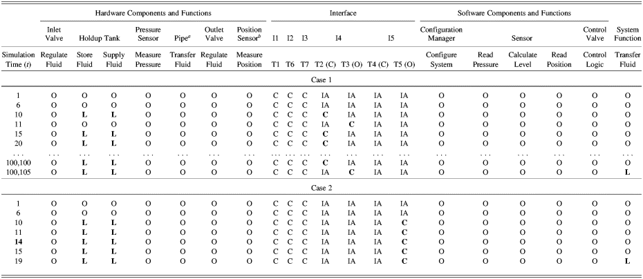
Case 1 illustrates a hypothetical scenario of how a holdup-tank-leak fault evolves, translates into valve failure, and eventually leads to system failure. We assume that all the interfaces are in a healthy condition, all transactions have [min, max] time limit of [0, 1Footnote 3], and the transactions are activated and completed within the time limit.
The simulation (Fig. 8) begins and the initial conditions set are no faults are injected, all HW and SW components exhibit nominal behavior, and all transactions are inactive, that is, [start, finish] = [0, 0] (Table 5). Other initial conditions include holdup tank is half full (i.e., PLTh < P < PUTh) and the inlet and the outlet valves are Nominal ON (i.e., open). With these initial conditions, the simulation is performed and results are recorded in Table 11 under Case 1. Some of the important steps and results of the simulation are discussed below.
Simulation results
Note: For simulation, imagine Qivin = Qovout = 10 units, Qleak = 2 units, LL = 2 units, and LU = 20 units. Hence, the Qout of tank is 12 units and level decreases by 2 units in each simulation step. Case 1: Valve failure; fault injected: tank leak at t = 6. Case 2: incorrect modification of software; fault injected: tank leak at t = 6. O, operating; L, lost; IA, inactive; C, complete.
a“Pipe” corresponds to pipe1, pipe2, pipe3, and pipe4.
bThe position sensor corresponds to both the inlet and the outlet valve's position sensors.
Path p1 (in Fig. 8) leads to execution of the CFG (Fig. 11) and path p2 (in Fig. 8) leads to execution of the Activity diagram (Fig. 13). The execution along path p1 and p2 is explained next.
Along path p1 the first component of the CFG, pipe1, is identified (Fig. 8 along path p3). It has one function, transfer fluid (Table 7), and has one inflow (Q1in), one outflow (Q1out), and none of them is a transaction (Table 9). This leads to execution of the transfer fluid function (Fig. 8 along path p6). Since no faults are injected, the execution of behavioral rules concludes that pipe1 exhibits nominal behavior (Table 9). Along path p7, the execution of the FFL indicates the transfer fluid function is operating (Table 9). Path p8 leads to paths p9 and p10 since there are no outgoing transactions. Along path 10, since the pipe1 component has only one function, the path leads to identification of the next component, the inlet valve.
Inlet valve has one function, regulate fluid (Table 7); two inputs, Qivin and ≪signal≫T4 or ≪signal≫T5 (Table 9 and Fig. 12); and one output, Qivout. The transactions are not created by the SW; thus, they have default values, that is, [start, finish] = [0, 0], which indicates the transactions' status is inactive (Table 5). Next, we execute the regulate fluid function (along path p6). Since no faults are injected, the execution of behavioral rules concludes that the inlet valve exhibits nominal behavior (Table 9). Further along path p7 execution of the FFL indicates the regulate fluid function status as operating (Table 9). Path p8 leads to paths p9 and p10 since there are no outgoing transactions. Along path 10, since the inlet valve has only one function, we move on to identify the next component in the CFG. After inlet valve, there are two components: position sensor1 and pipe2. We select position sensor1 as the next component and then pipe2, since parallel execution of components in the CFG is not currently possible.
Position sensor1 has one function, measure position (Table 7); one inflow, Pos; and two outflows, Pos and ≪signal≫T6 (Table 9). This leads to execution of the measure position function (Fig. 8 along path p6). Since no faults are injected, the execution of behavioral rules concludes that position sensor1 exhibits nominal behavior (Table 9). Along path p7, the execution of the FFL indicates the measure position function is operating (Table 9). Path p8 leads to path p11 and path 12 since there is one outgoing transaction. Along path p12 a transaction ≪signal≫T6 is created and its [start, finish] value changes to [1, 0], which indicates its status is active (Table 5). Path p8 leads to path p9 and path p10. Along path p10, since the position sensor1 component has only one function, the path leads to identification of the next component, pipe2, as mentioned earlier. Execution of pipe2 is identical to the execution of pipe1 discussed before. Following pipe2, the next component is holdup tank.
Holdup tank has two functions, store fluid and supply fluid (Table 7), and has one inflow (Qin) and one outflow (Qout) (Table 9). For the first function, store fluid, there is no incoming transaction, thus leading to the execution of the store fluid function (along path p6). Since no faults are injected, the execution of behavioral rules concludes that holdup tank exhibits nominal behavior (Table 9). Along path p7, the execution of the FFL indicates that the store fluid function is operating (Table 9). Path p8 leads to paths p9 and p10 since there are no outgoing transactions. Along path 10, since the holdup tank component has another function, the path leads to identification of the next function, supply fluid. There is no incoming transaction, thus leading to the execution of the supply fluid function (Fig. 8 along path p6). Since no faults are injected, the execution of behavioral rules concludes that holdup tank exhibits nominal behavior (Table 9). Along path p7, the execution of the FFL indicates that the supply fluid function is operating (Table 9). Path p8 leads to paths p9 and p10 since there are no outgoing transactions. Along path 10, since the last function of holdup tank is evaluated, the path leads to identification of the next component. Holdup tank is connected to two components, pressure sensor and pipe3. Since the simulation procedure is not set for parallel execution, the pressure sensor component is selected first and pipe3 as the next component.
Pressure sensor has one function, measure pressure (Table 7); one inflow, Pin; and two outflows, Pout and ≪signal≫ T1 (Table 9). This leads to execution of the measure pressure function (Fig. 8 along path p6). Since no faults are injected, the execution of behavioral rules concludes that the pressure sensor exhibits nominal behavior (Table 9). Along path p7, the execution of the FFL indicates that the measure pressure function is operating (Table 9). Path p8 leads to paths p11 and p12 since there is one outgoing transaction. Along path 12, a transaction ≪signal≫ T6 is created and its [start, finish] value changes to [1, 0], which indicates its status is active (will be updated in while execution of path p2). Eventually, path p8 leads to paths p9 and p10. Along p10, since the pressure sensor component has only one function, the path leads to identification of the next component, pipe3, as mentioned earlier. Execution of pipe3 is identical to execution of pipe1 discussed before. Following pipe3, the next component is outlet valve.
Outlet valve has one function, that is, regulate fluid (Table 7); two inputs, Qovin and ≪signal≫ T2 or ≪signal≫ T3 (Fig. 12); and one output, Qovout. The transactions are not created by the SW; thus, they have default values, [start, finish] = [0, 0], which indicates its status as inactive (Table 5). Next, we execute the regulate fluid function (Fig. 8 along path p6). Since no faults are injected, the execution of behavioral rules concludes that the outlet valve exhibits nominal behavior (Table 9). Along path p7, the execution of the FFL indicates the regulate fluid function status as operating (Table 9). Since the outlet valve has only one function, we move on to identify the next component in the CFG. After outlet valve, there are two components: position sensor2 and pipe4. We select position sensor2 as the next component and then pipe4, since parallel execution of components in the CFG is not currently possible.
Execution of the position sensor2 is identical to execution of the previously encountered position sensor1. Execution of pipe4 is identical to that of pipe1, discussed earlier. However, note that pipe4 is the last component of the CFG; thus, path p10 leads to the end of the CFG. The end of the CFG indicates the end of the HW design execution, which leads the execution path p1 to the AND2 gate.
Path p2 leads to execution of the main activity diagram (Fig. 13). The first activity read is configure system (along path A1 in Fig. 8). The corresponding component is configuration manager (Fig. 13), which has no inflows; one outflow, ConversionData (Table 9); and no transactions. Further, the path leads to A4 along which the activity configure system is executed, which will modify the output variables. Path A4 then leads to two concurrent paths: A5 and A6. Along A5, the behavioral rule of the component configuration manager is executed. Since no faults were injected, the component exhibits nominal behavior (Table 9). Next the FFL is executed, which indicates the configure system is operating. Path A6 leads to the next activity since there are no outgoing transactions from configure system. In Figure 13 we see that after configure system, the control flow branches out into two parallel flows owing to the fork. Since parallel execution of activities has not been set up yet in the ISFA simulation process, we will execute the activities in the following order: read pressure, calculate level, read position, store pos.
The next activity read is read pressure (along path A1). The corresponding component is sensor (Fig. 13), which has three inflows, ≪signal≫ T1, ≪signal≫ T6, and ≪signal≫ T7, and two outflows, Level and Pos (Table 9). The transaction input ≪signal≫ T1 (created during the HW design execution, path p1) is read without any error since no faults are injected. Thus the transaction's [start, finish] value is updated to [1, 1], which indicates the status is complete (Table 5). Note that the target of ≪signal≫ T6 and ≪signal≫ T7 are not read pressure activity (Fig. 13); thus, its status is not updated. Along A4, the activity read pressure is executed, which will modify the output variables. Path A4 then leads to two concurrent paths: A5 and A6. Along A5, the behavioral rule of the component sensor is executed. Since no faults were injected, the component exhibits nominal behavior (Table 9). Next the FFL is executed, which indicates that the read pressure is operating (Table 9). Path A6 leads to the next activity, calculate level.
The next activity is calculate level, and the corresponding component is sensor (Fig. 13), which has three inflows, that is, ≪signal≫ T1, ≪signal≫ T6, and ≪signal≫ T7, and two outflow, that is, Level and Pos (Table 9). The target of the transactions are not calculate level activity (refer to Fig. 12); thus, their status is not updated. Along A4, the activity calculate level is executed, which will modify the output variable Level. Path A4 then leads to two concurrent paths: A5 and A6. Along A5, the behavioral rule of the component sensor is executed. Since no faults were injected, the component exhibits nominal behavior (Table 9). Next, the FFL is executed, which indicates that the calculate level is operating. Path A6 leads to the next activity, read position.
The next activity is read position (along path A1in Fig. 8) and the corresponding component is sensor (Fig. 13), which has three inflows, ≪signal≫ T1, ≪signal≫ T6, and ≪signal≫ T7, and two outflows, Level and Pos (Table 9). The transaction inputs ≪signal≫ T6 and ≪signal≫ T7 are read without any error since no transaction faults are injected. Thus the transaction's [start, finish] value changes to [1, 1], which indicates that the status is complete (Table 5). Note that the target of ≪signal≫ T1 is not read position activity (Fig. 12); thus, its status is not updated. Along A4, the activity read position is executed, which will modify the output variables. Path A4 then leads to two concurrent paths: A5 and A6. Along A5, the behavioral rule of the sensor is executed. Since no faults were injected, the component exhibits nominal behavior (Table 9). Next, the FFL is executed, which indicates that the read position is operating. Path A6 leads to the next activity, store pos.
The next activity is store pos (along path A1), and the corresponding component is sensor (Fig. 13), which has three inflows, ≪signal≫ T1, ≪signal≫ T6, and ≪signal≫ T7, and two outflows, Level and Pos (Table 9). The target of the transactions are not store pos activity (refer to Fig. 12); thus, their status is not updated. Along A4, the activity store pos is executed, which will modify the output variable Pos. Path A4 then leads to two concurrent paths: A5 and A6. Along A5, the behavioral rule of the component sensor is executed. Since no faults were injected, the component exhibits nominal behavior (Table 9). Next, the FFL is executed, which indicates that the store pos is operating. Path A6 leads to the next activity, valve control logic. Valve control logic is further decomposed into other activities (Fig. 14).
The valve control logic is enclosed in the component Valve Controller (Fig. 14), which has two inflows, Level and Pos (Table 9), and five outflows, ControlCommand, ≪signal≫ T2, ≪signal≫ T3, ≪signal≫ T4, and ≪signal≫ T5 (Table 9). The execution of valve control logic traces the path D1– D2–D3–Exit. Thus, the output variables are not modified.
The transactions ≪signal≫ T2, ≪signal≫ T3, ≪signal≫ T4, or ≪signal≫ T5 are not created; thus, their [start, finish] value remains [0, 0], which indicates that their status is inactive (Table 5). Path A4 then leads to two concurrent paths: A5 and A6. Along A5, the behavioral rule of the component Valve Controller is executed. Since no faults were injected, the component exhibits nominal behavior (Table 9). Next, the FFL is executed, which indicates that the valve control logic is operating. Since valve control logic is the last activity, the end of the main activity diagram (Fig. 13) is reached. The end of the activity diagram indicates the end of the SW design execution, which leads the execution path p2 to the AND2 gate.
Paths p1 and p2 are synchronized at the AND2 gate, which further leads to the end of the first simulation step. For the next simulation step, the above procedure is repeated. During the execution of each step, the function status is captured and tabulated (Table 11). Some of the important results and their interpretation are discussed below.
At step t = 1, all the HW and SW functions were operating, and the transactions ≪signal≫ T1, ≪signal≫ T6, and ≪signal≫ T7 were complete. The transaction ≪signal≫ T2, ≪signal≫ T3, ≪signal≫ T4, and ≪signal≫ T5 were inactivate because the pressure was within the operating range [PLTh, PUTh], and both the valves were in open position (Fig. 14). Thus, the system function transfer fluid is operating.
At step t = 6, a tank leak fault is injected, and as such, the tank level started decreasing and reached a lower acceptable limit at t = 10. During this period from t = 6 to t = 10, all the HW and SW functions were in operating state, the water supply from the holdup tank was not interrupted, and thus the system function transfer fluid was operating.
At step t = 10, the holdup tank pressure dropped below the lower threshold value (PLTh) on account of the leak, and the backup system was started. The holdup tank's mode changed from nominal to dry-out; thus, its functions, supply fluid and store fluid, were inferred as lost (Table 9). The SW function valve control logic (Fig. 14) followed the path (D1–D5–D6–D7), causing a transaction ≪signal≫ T2, that is, close outlet valve, to occur. Thus, with only inflow and no outflow, the water level rose to the desired range and the holdup tank was available for the next time step. Note that the back system pumped water from the reservoir for one unit of time; thus, the system function transfer fluid was operating.
At step t = 11, the holdup tank functions were back to operating state, accompanied by a transaction change from ≪signal≫ T2 to ≪signal≫ T3. At this step, the system behaved similar to that at step t = 6, eventually leading to the holdup tank functions loss at step t = 15. At step t = 15, the system behaves similar to that at step t = 10. The backup system was switched ON, and the transaction ≪signal≫ T2 occurred.
The above system behavior continued up to step t = 100,100. At step t = 100,100, the outlet valve was closed. At this point, the valve reached its fatigue limit. From the next time step onward, the outlet valve's failure mode failed open is triggered. The backup system supplied water for the next five units of time (i.e., until t = 100,104), after which the system failure occurred at step t = 100,105.
In Case 1, the pattern of transaction and HW function status is worth noting. The transaction change from ≪signal≫ T2 to ≪signal≫ T3 and vice versa occurs every four units of time owing to the leak. In the absence of the leak, the outlet valve state would remain open. Thus, the transaction pattern indicates a symptom of fatigue failure of the outlet valve. The HW function status pattern indicates a symptom of small leak.
Case 2 illustrates a hypothetical scenario of how a classic SW modification fault (a commission error) evolves and translates into system failure. Before the SW modification, the variable Pos was set to values {1 or 0} corresponding to {Open or Close}. These values were stored in the computer memory during the execution of the valve control logic (Fig. 14). Later the SW design was modified in congruence with the holdup tank design change, that is, the decision to add a position sensor to each valve. So the SW was modified to read the valve's position data from the position sensor instead of from the computer memory. However, during the new SW modification, the position sensor data was read and the variable Pos was erroneously set to {0 or1} corresponding to {Open or Close} while the valve control logic was copied without any modification. The analysis of this commission error accompanied with the tank leak (same as Case 1) is performed using the ISFA simulation process (Fig. 8). Important results of the simulation are explained below.
At step t = 1 (same as Case 1), all the HW and SW functions were operating, and the transactions ≪signal≫ T1, ≪signal≫ T6, and ≪signal≫ T7 were complete. The transactions ≪signal≫ T2, ≪signal≫ T3, ≪signal≫ T4, and ≪signal≫ T5 were inactive because the pressure was within the operating range [PLTh, PUTh], and both the valves were in open position (Fig. 14). Thus, the system function transfer fluid is operating.
At step t = 6, the system behavior was also the same as in Case 1 (step t = 6) explained earlier. However, at step t =10, when the pressure goes below the lower threshold, the execution of activity diagram (Fig. 14) takes a different path (D1–D5–D6–D8–Exit) than in Case 1. As a consequence, the transaction ≪signal≫ T5, that is, open inlet valve, was observed while ≪signal≫ T4 remained inactive. At the same time, the backup was switched ON, so the system function transfer fluid was operating. However, the holdup tank's mode changed from nominal to dry-out; thus, its functions, supply fluid and store fluid, were inferred as lost (Table 9).
At step t = 11, the holdup tank pressure was still below the lower threshold value since the outlet valve was open. Thus, the water kept draining from the tank accompanied by the leakage. Therefore, the backup system was ON. This condition continued until step t = 14, when the backup system's limited reservoir was depleted. During this period the system function transfer fluid was operating.
After step t = 14 until step t = 19, the water supply from the tank was less than required owing to the leak. Thus for five units of time the nuclear core did not get the required amount of water, leading to core uncover and thus the system function was lost.
In Case 2, the pattern of transaction and HW function status is worth noting. The transaction ≪signal≫ T5 is always activated on account of combined SW modification fault and tank leak fault. In the absence of leak, the outlet valve would always be open and the transaction ≪signal≫ T2 and ≪signal≫ T3 would always remain inactive in the presence of the SW fault. Thus, the given SW fault will have no impact on the system function under the nominal behavior of the components, giving an impression that the SW modification was correct. Thus, observing the transaction status pattern can give an insight into the type of fault (HW, SW, or both).
Case 1 and Case 2 demonstrate that we can propagate HW fault and SW faults independently and simultaneously. In addition, we can evaluate the system-level functional impact of the combined faults. In general, the system function loss can occur as a result of component or function failure, and interaction failure. Impact analysis of all these failures requires an integrated domain model representation to enable seamless fault propagation.
5. CONCLUSION
The ISFA method is presented as a method to enhance traditional techniques such as FMEA and FTA by addressing some of the inherent difficulties of using these methods in complex systems. In an FMEA, engineers are expected to identify the potential effects, to determine causes and controls, and to assign a qualitative score to the severity, likelihood of occurrence, and detectability of a particular fault. However, the format of an FMEA limits the ability to evaluate multiple faults, such as the combined SW and outlet valve in Case 2. Further, it is left to designer judgment to identify the propagation and severity of the fault. Both of these are identified automatically with ISFA. The propagation path is a systematic outcome of each simulation step. For example, at time step t = 10, the propagation path includes D1–D5–D6–D7 (Fig. 14) along which ≪signal≫ T2 is activated (Table 11), while at time step t = 11, the path includes D1–D2–D3 (Fig. 14) along which ≪signal≫ T3 (Table 11) is activated. In the case study discussed, the severity of a fault is dependent upon the time to system failure. The severity is very low if the system failure occurs after 100,000 time steps, medium if the failure occurs between time steps t = 10,000 and t = 100,000, high if failure occurs between time steps t = 1000 and t = 10,000, and very high if the failure occurs between time steps t = 1 and t = 1000. Thus, the results (Table 11) indicate the severity of incorrect SW modification fault combined with tank leak' fault (Case 2) is very high since the system failure occurs at time step t = 19, while in Case 1 the severity of the tank leak fault alone is very low since the system failure occurs at time step t = 100,105. FTA shows a partial listing of the faults that might lead to the system-level failure of loss of fluid supply. The FTA process requires that engineers thoroughly evaluate potential causes and identify all the potential causalities. This time-consuming process is simplified in the ISFA simulation approach. Further, simulation results provide additional impacts to the system, such as the loss of fluid transportation or flow detection.
Another advantage of ISFA is that identification of the fault-propagation paths is inductive. No a priori fault-propagation paths are defined. The fault-propagation path is an outcome of the simulation of any fault that can be injected at any point in time during the simulation process. Existing fault-propagation analysis tools, such as TEAMS (QSI Tool), SymCure (Kapadia, Reference Kapadia2003), and the HFPG (Mosterman & Biswas, Reference Mosterman and Biswas1999), require designers to explicitly formulate a fault-propagation model by specifying paths of causal relationships. In contrast, ISFA only uses information available during the design stage to determine potential failures and their propagation paths. Further, this propagation is identified through component behavioral simulation rather than functional dependencies (Kruse & Grantham Lough, Reference Krus and Grantham Lough2009).
Because SW faults give rise to unexpected failures, the addition of SW control increases the nonlinearity of the system. ISFA captures various nonlinear aspects of fault propagation. It is simplistic and often incorrect to assume that faults propagate by following the functional or structural connectivity of a system. For example, a “leak” in the tank should not impose any fault propagation to its neighboring components and functions. Similarly, the Store Pos SW fault should only affect the component it controls. However, we see nonlinear behavior: the SW failure does not immediately affect the physical system, but as the fault persists, the Regulate fluid function is lost, leading to total system failure. However, these two functions are unconnected to the valve and SW control and not on the downstream path in the function model. With ISFA, a proper mapping among the system behavior, its physical state, and the system functions will enable the identification of these nontrivial, nonlinear, fault-propagation paths.
An additional feature of ISFA is its ability to identify functional failures that result from global component interactions, masked fault activation, and timing faults. In Case 2, the tank leak fault was initially active for some time, but the simulation indicated that the SW was able to maintain normal operation for a few time steps, thereby masking the leak fault. However, over a period of time, the transaction frequency activated a valve failure, resulting in the loss of store fluid, supply fluid, and regulate fluid. Therefore, even though the transactions occur normally, their timing and frequency can potentially lead to system failure.
The case study also demonstrated that the simulation can be performed directly on a high-level design without any implementation level details or model transformation. Different components, functions, and communication models can be inserted into the design and analyzed to develop an optimum design early in the design phase. The analysis is qualitative but powerful enough to identify areas of potential failures. Such failures would typically remain unnoticed in the early design phase, only to be discovered later in the development process. At such a point, significant resources would have been committed, subsystems would have been fully defined and assembled, and levels of detail would have escalated, precluding exhaustive analysis.
This paper addressed a limited case study intentionally designed to demonstrate nonlinear behavior and interactions but was not overly complicated. There are two main considerations for scaling this to a realistic system. These two considerations include the time required to simulate and test a scenario and the amount of scenarios to test. The time required to simulate a particular scenario will be dependent on the solver and the level of model complexity. The simple component state machines used in this method can be solved quite rapidly. Further better solvers have built-in capabilities to skip solving some state machines if no transition is going to occur. The alternative approach is to model at higher abstractions. For example, we could model the holdup tank and controller as a single state machine interacting with the rest of some larger system. The second issue is the completeness in the number of scenarios to test. A baseline is testing each component fault mode by itself. This would produce the same result as a detailed FMEA. The strength of ISFA is the ability to test multiple faults. Reliability requirements can be used to specify a number of allowable faults where a system must remain functional. Without an intelligent method of picking scenarios, a brute force method of working through each combination of faults is possible if a system is allowed only 2–3 faults.
In conclusion, the ISFA method provides constructs for multiple-domain representation, thereby providing a unique system-level model. In addition, ISFA provides an execution model to simulate the system model. This enables designers to understand the interactions that may lead to functional failures and help them improve the system quality at the earliest stages of the design process.
6. FUTURE RESEARCH
In this paper, a sophisticated functional fault-propagation approach was described in which a set of behavioral rules was one of the important components to identify the functional failure. Although these rules are based on first principles and expert opinions, these rules can be enhanced to include AI-specific fuzzy logic, heuristics, or probabilistic techniques. The formal nature of the ISFA technique expressed in one common MOF language lends itself to a desired integration of AI into design (Brown, Reference Brown2007).
Another interesting extension to ISFA would be to integrate backtracking algorithms into the ISFA technique, such that exact location and nature of the faults that lead to particular system level failures could be automatically determined and design modifications that prevent the propagation of such faults suggested. The fault propagation and its impact on the modified design can be reanalyzed, thus converging progressively toward highly reliable design.
For complex systems, an exhaustive analysis of all possible scenarios is infeasible. Intelligent-scenario-selection algorithms could be developed to study the most critical fault combination.
Algorithms could be developed to analyze/learn the patterns of transaction and HW/SW function status, leading to further degradation (e.g., the repeated cycling of the outlet valve in Case 2 of Section 4.5 due to the tank leak finally leading to a permanent failed closed wear failure of the valve). These particular patterns could give useful insights into the degree of impact a particular fault could have on the system and may help identify design configurations that should be avoided. Such design configurations could be stored in a design library and a new design analyzed to verify that the configurations cannot be found in the design, or at least these could be flagged as a potential risk.
ACKNOWLEDGMENTS
This research was supported by the Air Force Office of Scientific Research (under Grants AFOSR FA9550-08-1-0158 and AFOSR FA9550-08-1-0139) and the Department of Energy (under Grant GRT00021770). In addition, we acknowledge Matt Gerber for editing this paper. We also thank the reviewers for their constructive comments. Any opinions or findings of this work are the responsibility of the authors and do not necessarily reflect the views of the sponsors or collaborators.
Chetan Mutha is a PhD student in the Department of Mechanical and Aerospace Engineering at Ohio State University. His research interests include systems and software reliability assessment, integrated system design and analysis, and fault diagnosis early in the design phase. He has published three conference papers. He works in the Risk and Reliability Laboratory located at Ohio State University and is advised by Dr. Carol Smidts. His research has been funded through government agencies such as the Air Force Office of Scientific Research, the Department of Defense, and the Nuclear Regulatory Commission.
David Jensen is an Assistant Professor at the University of Arkansas in the Department of Mechanical Engineering, where he teaches courses in design and mechanics. One of his teaching goals is incorporating “systems thinking” into fundamental engineering coursework to better prepare engineers for working with advance technologies and industries. He earned his doctorate in mechanical engineering at Oregon State University. His research has focused on modeling and assuring safety in the early design stage of engineered systems. He has collaborated extensively with researchers in industry and academia to perform cutting-edge research in model-based prediction of system failure behavior and systems validation. His research has been funded through government agencies such as NASA, the Defense Advanced Research Projects Agency, and the Air Force Office of Scientific Research.
Irem Tumer is an Associate Professor at Oregon State University, where she leads the Complex Engineered System Design Laboratory. She received her PhD in mechanical engineering from the University of Texas at Austin in 1998. Prior to accepting a faculty position at Oregon State University, Dr. Tumer led the Complex Systems Design and Engineering Group in the Intelligent Systems Division at NASA Ames Research Center, where she worked from 1998 through 2006 as research scientist, group lead, and program manager. Her research focuses on the overall problem of designing highly complex and integrated engineering systems with reduced risk of failures and developing formal methodologies and approaches for complex system design and analysis. Since moving to Oregon State University in 2006, her funding has largely been through the National Science Foundation, the Air Force Office of Scientific Research, the Defense Advanced Research Projects Agency, and NASA.
Carol Smidts is a Professor in the Department of Mechanical and Aerospace Engineering at Ohio State University. She graduated with a BS/MS and PhD from the Université Libre de Bruxelles, Belgium, in 1986 and 1991, respectively. She was a Professor at the University of Maryland at College Park in the Reliability Engineering Program from 1994 to 2008. Her research interests are in software reliability, SW safety, SW testing, PRA, and human reliability. She is a senior member of the Institute of Electrical and Electronic Engineers; an Associate Editor of IEEE Transactions on Reliability; and a member of the editorial board of Software Testing, Verification, and Reliability.
APPENDIX A
Nomenclature
- ESD
event sequence diagram
- FFIP
functional failure identification and propagation
- FFL
function failure logic
- FMEA
failure mode effect analysis
- FPSA
failure propagation and simulation approach
- FTA
fault tree analysis
- HW
hardware
- ISFA
integrated system failure analysis
- MOF
meta-object facility
- PRA
probabilistic risk assessment
- SW
software
- SysML
System Modeling Language
- UML
Unified Modeling Language