1. Introduction
Recent developments in technologies related to unmanned aerial vehicles (UAVs) have made them very popular in many applications as agile mobile platforms with low operational costs. It has become possible with UAVs to perform hard tasks in unreachable harsh environments that are risky to human lives. One important problem in this area is the safe navigation of unmanned aerial vehicles through unknown tunnel-like environments which is the main focus of this study. This problem arises in many industrial applications such as navigation of flying robots through underground mines and connected tunnels, navigating small aerial vehicles in cluttered indoor environments, 3D mapping of cave networks, interior inspection of pipeline networks, search & rescue missions during disaster events in underground rail networks, etc. For example, some variants of these applications that have gained a great interest by researchers recently are dam penstocks inspection and/or mapping [Reference Özaslan, Shen, Mulgaonkar, Michael and Kumar1–Reference Özaslan, Loianno, Keller, Taylor and Kumar4], chimney inspection [Reference Quenzel, Nieuwenhuisen, Droeschel, Beul, Houben and Behnke5], hazardous deep tunnels inspection [Reference Tan, Ng, Shaiful, Win, Ang, Yeung, Lim, Do and Foong6,Reference Tan7], mapping and navigation in underground mines/tunnels [Reference Mansouri, Kanellakis, Georgoulas and Nikolakopoulos8–Reference Turner, MacLaughlin and Iverson16], search & rescue in underground mines [Reference Dang, Mascarich, Khattak, Nguyen, Nguyen, Hirsh, Reinhart, Papachristos and Alexis17,Reference Petrlk, BÁČa, HeŘt, Vrba, Krajnk and Saska18], inspection of ventilation systems [Reference Petrlk, BÁČa, HeŘt, Vrba, Krajnk and Saska18], inspection of narrow sewer tunnels [Reference Chataigner, Cavestany, Soler, Rizzo, Gonzalez, Bosch, Gibert, Torrente, Gomez and Serrano19] and inspection tasks in the oil industry [Reference Shukla and Karki20]. In all these applications, a UAV should navigate through a tunnel-like unknown environment while avoiding collisions with the tunnel walls. A more favorable behavior is to have a fully autonomous operation with least human interaction. This problem is highly challenging due to several factors that may vary from one environment to another such as poor lighting conditions, narrow flying space, absence of GPS signals and featureless structures. Some other challenging factors are vehicle-specific such as sensing capability, payload capacity, onboard computing power and maximum flight time. All these factors have a great effect on the overall system design and navigation algorithm development.
The problem under consideration is also of great importance to many marine applications with autonomous underwater vehicles (AUVs) where it is required to navigate through underwater tunnel-like environments. This include applications in underwater geology and archeology, inspecting different kinds of underwater structures, military operations, inspecting flooded spring tunnels, bypass tunnels for dams, storm run-off networks and freshwater delivery tunnels, etc (for example, see refs. [Reference Mallios, Ridao, Ribas, Carreras and Camilli21–Reference Gary, Fairfield, Stone, Wettergreen, Kantor and Sharp31] and references therein).
In general, existing solutions to the navigation problem in unknown environments may be classified into planning-based or reactive methods. Planning-based approaches require a map representation of the environment and localization information to find safe paths locally. Local path planning normally adopts an optimization-based or sampling-based search approach. As the search space size increases, the computational cost of such algorithms becomes more expensive [Reference Li and Liu32]. These approaches mostly rely on simultaneous localization and mapping (SLAM) techniques to allow for autonomous operation in unknown environments. On contrary, reactive approaches may directly generate motion decisions based on light processing of current sensors observations to produce reflex-like reactions [Reference Hoy, Matveev and Savkin33]. These methods can provide a better computational cost compared with planning-based methods without the need for accurate localization.
The available methods addressing the navigation problem of interest suggest different approaches in terms of the overall system design, the level of autonomy and the algorithm adopted to traverse the tunnel. The choices made for UAV system design are mostly made specifically to serve a specific application. The use of redundant sensors may be found common among different systems to attain a fully autonomous operation in some harsh environments by combining range and vision-based sensors. Depending only on one kind of sensors may cause the system to fail at some situations. For example, range sensors can suffer from wet structures causing them to fail sometimes, and vision-based solutions may be useless against textureless environments [Reference Özaslan, Mohta, Keller, Mulgaonkar, Taylor, Kumar, Wozencraft and Hood2]. An evaluation of localization solutions in underground mines based solely on cameras can be found in ref. [Reference Kanellakis and Nikolakopoulos34]. Therefore, it is common in the available solutions to use multi-modal sensors which can improve localization and/or reactive responses to cope with the harsh conditions in tunnel environments. The following subsection summarizes some of the recent solutions.
1.1. Related work
Many of the available navigation methods tackling the same problem fall under the planning-based category where the main focus of the development is shifted toward the localization system design. For example, the approach presented in ref. [Reference Özaslan, Shen, Mulgaonkar, Michael and Kumar1] suggested a combination of Unscented Kalman Filter (UKF) and a particle filter to process IMU and range measurements for UAV localization in dam penstocks where a map was available a priori. Then, the navigation was achieved in a semi-autonomous fashion to perform an inspection task where a remote operator was sending goal position commands to guide the UAV through the tunnel environment. Extensions were then proposed in refs. [Reference Özaslan, Mohta, Keller, Mulgaonkar, Taylor, Kumar, Wozencraft and Hood2,Reference Özaslan, Loianno, Keller, Taylor, Kumar, Wozencraft and Hood3] in an effort toward a more autonomous solution for penstocks inspection with UAVs. In ref. [Reference Özaslan, Mohta, Keller, Mulgaonkar, Taylor, Kumar, Wozencraft and Hood2], UKF was used to provide 6-DOF estimation of the UAV pose by fusing data from IMU, two range sensors and four cameras against a 3D occupancy grid map known in advance. However, a remote operator was still needed to provide waypoints to guide the UAV. A SLAM-based approach was then suggested in ref. [Reference Özaslan, Loianno, Keller, Taylor, Kumar, Wozencraft and Hood3] combining range and vision-based estimators. An algorithm was proposed to perform local mapping where fitting a cylindrical model was applied to point clouds obtained from the heterogeneous sensors. Then, the tunnel axis is estimated from the local map, and the UAV position is determined along the tunnel axis which was then used to guide the UAV.
Another SLAM-based method was presented in ref. [Reference Mascarich, Khattak, Papachristos and Alexis9] to address the problem of autonomous exploration and mapping in underground tunnels using a UAV equipped with two IMUs, four cameras and three depth sensors. The open-source Robust Visual Inertial Odometry framework [Reference Bloesch, Omari, Hutter and Siegwart35] was adopted in that work to perform SLAM. A local planner based on rapidly exploring random tree algorithm was used in a receding horizon manner to generate motion commands toward a direction that maximizes some exploration gain. The same SLAM framework and local planning algorithm were also used in ref. [Reference Papachristos, Khattak, Mascarich and Alexis36]. Similarly, a local planner based on the rapidly exploring random graph algorithm is used in refs. [Reference Dang, Mascarich, Khattak, Nguyen, Nguyen, Hirsh, Reinhart, Papachristos and Alexis17,Reference Dang, Mascarich, Khattak, Nguyen, Khedekar, Papachristos and Alexis37] to guide the UAV maximizing volumetric exploration gain in underground tunnels with multiple branching locations. In these works, data from range, thermal, vision and inertial sensors are fused as a part of their SLAM implementation (sometimes using only a subset of these sensors). In ref. [Reference Petrlk, BÁČa, HeŘt, Vrba, Krajnk and Saska18], a different approach was presented for operations in extremely narrow tunnels to find safe paths using a modified A* algorithm in 2D occupancy maps generated by onboard SLAM. A low-level model predictive controller was used to track generated local trajectories based on the planned paths.
Inspection of deep tunnels (i.e. vertical) was also addressed in refs. [Reference Tan, Ng, Shaiful, Win, Ang, Yeung, Lim, Do and Foong6,Reference Tan7] where the authors suggested the use of a UAV with a rotating camera for minimal field-of-view (FOV) obstructions when collecting images for inspection. Localization was performed using measurements from an array of laser range sensors to estimate the UAV position and heading in the tunnel with a prior knowledge about its geometry. They also proposed a method to estimate the tunnel axis using measurements from the sensors array. Their navigation method was based on maintaining the localized position of the UAV at the center of the tunnel. Additionally, an optical-flow sensor was used with a time-of-flight range sensor to estimate the distance travelled along the tunnel axis.
A rather different approach based on deep learning was presented in refs. [Reference Mansouri, Kanellakis, Georgoulas and Nikolakopoulos8,Reference Mansouri, Kanellakis, Karvelis, Kominiak and Nikolakopoulos13,Reference Mansouri, Kanellakis, Kominiak and Nikolakopoulos15] for navigation in underground mines. These works suggested a low-cost UAV system design which relies only on a single camera with LED light bar. Convolution Neural Network was used to classify images into three categories (left, center and right) which was then used to correct the UAV heading to avoid collisions with tunnel walls without relying on localization information. The UAV motion was controlled in the horizontal plane with a fixed altitude provided by a remote operator. The performance of such methods relies on how good the training data set is which can be challenging when deployed in new environments.
On the other hand, some reactive methods have been proposed to address the general problem of navigation in tunnel-like environments such as refs. [Reference Savkin and Wang38–Reference Matveev, Magerkin and Savkin40] which rely only on local sensory depth information of the surrounding tunnel walls. In these works, a 3D nonholonomic kinematic model is considered for the motion, and rigorous mathematical proofs of the methods’ performance are provided. In ref. [Reference Savkin and Wang38], a control law was developed to maintain a movement in a direction parallel to the tunnel axis while keeping a safe distance from tunnel walls. Alternatively, refs. [Reference Matveev and Savkin39,Reference Matveev, Magerkin and Savkin40] presented a method based on estimating a direction parallel to a nearby sensed patch of the tunnel surface in the direction of progressive motion through the tunnel.
1.2. Paper contributions
The main contributions of this paper can be highlighted as follows:
• A novel collision-free autonomous navigation method is proposed in this work for UAVs flying in unknown 3D tunnel-like environments.
• Rigorous mathematical proof is provided, in contrast to many of the existing methods, to show that our method can safely guide the UAV to progressively advance through the environment.
• Detailed implementation approach is suggested for quadrotor UAVs considering the system dynamics and suggesting a low-level sliding mode controller design.
• Perception pipelines and algorithms with different computational costs based on the suggested method are proposed for simple and robust implementations with narrow field-of-view sensors.
• Experimental results with a quadrotor are given to further validate the overall approach and discuss some of the practical aspects to consider.
The novelty of the approach is that it can handle movements in tunnel-like environments that changes shape and direction in 3D in a reactive manner where it is not suitable to use any of the existing 2D reactive approaches as they constraint UAV movement to some fixed altitude. On contrary to available 3D planning-based approaches, our method can provide a computationally light solution for the autonomous navigation problem which can be suitable for vehicles with limited resources. Motion decisions are mainly based on available measurements from onboard sensors to guide the UAV with no need for accurate localization. The suggested method can also benefit from available local maps of the surroundings if one exists.
The general idea adopted here is to move the UAV toward estimated 3D points on the tunnel curvy axis in the direction of progressive movement through the tunnel. These points are interpreted from available depth measurements of the tunnel walls which can be for example in the form of 3D point clouds represented in a sensor-fixed coordinate frame. Note that we do not consider environments filled with obstacles. However, it is possible to extend our approach to consider those environments by combining it with a reactive obstacle avoidance law using a behavior-based control approach; for example, see refs. [Reference Hoy, Matveev and Savkin33,Reference Matveev, Teimoori and Savkin41–Reference Elmokadem43] and references therein. The use of a general kinematic model for the development makes our approach applicable to vehicles moving in 3D such as UAVs of different types (multi-rotors and fixed-wing) and autonomous underwater vehicles. Slight modifications could be done to take into consideration nonholonomic constraints related to some vehicles such as fixed-wing UAVs. Computer simulations and practical experiments were carried out to evaluate the performance of our approach in different and complex 3D tunnel-like structures. A realistic sensing model was used in all simulations in addition to considering noisy measurements to investigate the robustness of the suggested method, and different sensors configurations and perception algorithms were used in the real experiments.
1.3. Paper outline
This paper is structured as follows. The UAV navigation problem in tunnel-like environments is defined in Section 2 considering a general kinematic model. The proposed navigation algorithm is then presented in Section 3. Our navigation algorithm is first validated through several simulation scenarios considering different environments, the details and results of these simulations are given in Section 4. After that, implementation details with quadrotor UAVs are presented in Section 5. Proof-of-concept experiments were carried out to validate the performance of our navigation method. The used quadrotor UAV system and the experiment set-up are described in Section 6 along with the results. Finally, this work is concluded in Section 7.
2. Kinematic model and navigation problem
We consider an autonomous UAV whose motion is described by the kinematic model: let  $c(t)\,:\!=\,[x(t),y(t),z(t)]$ be the three-dimensional vector of the UAV’s Cartesian coordinates defined in a world (inertial) reference frame. Then, the motion of the UAV is described by the equation:
 \begin{equation}\dot{c}(t) = V(t).\end{equation}
Here,  $V(t)\in \mathbb{R}^3$ is the linear velocity vector,
 $\|V(t)\|=v$ for all t, where
 $v>0$ is some given constant, and
 $\|\cdot\|$ denotes the standard Euclidean vector norm. The vector variable V(t) is the control input, v is the speed or linear velocity of the UAV, hence, the UAV is moving with a constant speed. We assume that the control input V(t) is updated at discrete times
 $0,\delta,2\delta,3\delta, \ldots$:
 \begin{equation}V(t)\,:\!=\,V_k~~~\forall t\in [k\delta,(k+1)\delta),~~~\forall k=0,1,2,\ldots\end{equation}
where  $\delta>0$ is the sampling period. The kinematics of many unmanned aerial and underwater vehicles can be described by the model (1) or its slight modifications.
We consider a quite general three-dimensional problem of autonomous UAV navigation in unknown tunnel-like environments with collision avoidance.
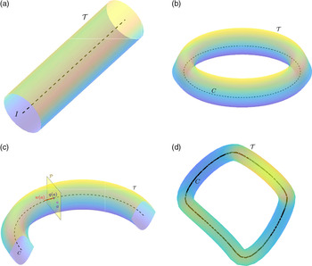
Definition 1. Let I be a straight line in  $\mathbb{R}^3$, and P be a closed, bounded, connected and linearly connected planar set. Then, the three-dimensional set
 ${\mathcal T}\,:\!=\,I\times P$ is called a perfect cylindrical tunnel, and the straight line I is called the axis of the perfect cylindrical tunnel
 ${\mathcal T}$ (see Fig. 1(a)). Furthermore, the set
 ${\mathcal W}$ of all the boundary points of
 ${\mathcal T}$ is called the wall of the perfect tunnel
 ${\mathcal T}$. Furthermore, let C be a circle in
 $\mathbb{R}^3$, and P be a closed, bounded, connected and linearly connected planar set. Then, the three-dimensional set
 ${\mathcal T}\,:\!=\,C\times P$ is called a perfect torus-shaped tunnel, and the circle C is called the axis of the perfect torus-shaped tunnel
 ${\mathcal T}$ (see Fig. 1(b)).
An illustration of tunnels definitions. (a) Perfect cylindrical tunnel. (b) Perfect torus-shaped tunnel. (c) Deformed cylindrical tunnel. (d) Deformed torus-shaped tunnel

Now we can introduce the following definition generalizing Definition 1.
Definition 2. Let C be a smooth non-self-intersecting infinite (or closed) curve in  $\mathbb{R}^3$. Assume that for any point
 $q\in C$ there exists a closed, bounded, connected and linearly connected planar set P(q) intersecting C at the only point q and such that the plane of P(q) is orthogonal to C at the point q. Also, we assume that
 $P(q_1)$ and
 $P(q_2)$ do not overlap for any
 $q_1\neq q_2$. Then, the three-dimensional set
 ${\mathcal T}\,:\!=\,\cup_{q\in C} P(q)$ is called a deformed cylindrical (or torus-shaped) tunnel, and the curve C is called the curvy axis of the deformed tunnel
 ${\mathcal T}$, see Fig. 1(c)–(d). Furthermore, the set
 ${\mathcal W}$ of all the boundary points of
 ${\mathcal T}$ is called the wall of the deformed cylindrical (torus-shaped) tunnel
 ${\mathcal T}$.
It is obvious that perfect tunnels are special cases of deformed tunnels where the axis is either a straight line or a circle and all sets P(q) are identical.
Notations: We introduce some curvilinear coordinate along the curvy axes C so that the difference of the coordinates of any two points of C is the length of the segment of C between them. In the case of a deformed cylindrical tunnel, the curvilinear coordinate takes values in  $(-\infty, +\infty)$, and in the case of deformed torus-like tunnel, the curvilinear coordinate takes values in [0,L) where
 $L>0$ is the length of the closed axis curve C. By Definition 2, for any point a in the deformed tunnel
 ${\mathcal T}$, there exists a unique
 $q(a)\in C$ such that
 $a\in P(q(a))$. Let
 $\tilde{q}(a)$ denote the curvilinear coordinate of q(a). Also, let r(a) denote the distance between the points a and q(a). Moreover, w(a) will denote the tangent vector to the curve C at the point q(a), see Fig. 1(c). Furthermore, let a be some point in the deformed tunnel, F be some vector, and
 $D_2>D_1\geq 0$ be given numbers. We introduce the points
 $O_1(a,F)$ and
 $O_2(a,F)$ ahead of the point a at the distances
 $D_1$ and
 $D_2$, respectively, in the direction of the vector F. Let
 ${\mathcal P}_1(a,F)$ and
 ${\mathcal P}_2(a,F)$ be the planes that are orthogonal to F and contain the points
 $O_1(a,F)$ and
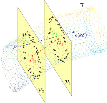
 $O_2(a,F)$, correspondingly; see Fig. 2 for
 $a=c(k\delta)$. Then, let
 $G_1(a,F)\in {\mathcal P}_1(a,F)$ and
 $G_2(a,F)\in {\mathcal P}_2(a,F)$ be the gravity centers of the sets of the tunnel wall points belonging to the planes
 ${\mathcal P}_1(a,F)$ and
 ${\mathcal P}_2(a,F)$, respectively. Furthermore, we introduce the vector A(a,F) departing from
 $G_1(a,F)$ to
 $G_2(a,F)$. Moreover, let h(a,F) denote the distance from the point a to the straight line connecting
 $G_1(a,F)$ and
 $G_2(a,F)$.
An illustration of available measurements along with the corresponding gravity centers computed according to our method

Available Measurements: Let  $D_2>D_1\geq 0 $ be given. We assume that for any time
 $t\geq 0$, the UAV can measure the coordinates of all the points of the tunnel wall lying in the planes
 ${\mathcal P}_1(c(t),V(t))$ and
 ${\mathcal P}_2(c(t),V(t))$; Fig. 2. Hence, the UAV can calculate the vector A(c(t),V(t)) and the number h(c(t),V(t)).
Definition 3. Let  $d_{safe}>0$ be a given constant, and let d(t) denote the distance between the robots’ coordinates c(t) and the wall of the deformed cylindrical or torus-shaped tunnel
 ${\mathcal T}$. A UAV navigation law is said to be safely navigating through the deformed cylindrical tunnel
 ${\mathcal T}$ if
 \begin{eqnarray}d(t)>d_{safe}~~~\forall t\geq 0,\end{eqnarray}
 \begin{eqnarray}\tilde{q}(c(t))\rightarrow\infty~~~as~~~t\rightarrow\infty. \end{eqnarray}
Moreover, a UAV navigation law is said to be safely navigating through the deformed torus-shaped tunnel  ${\mathcal T}$ if (3) holds and for any
 $Q\in [0,L)$ there exists a sequence
 $t_k\rightarrow+\infty$ such that
 \begin{eqnarray}\tilde{q}(c(t_k))=Q.\end{eqnarray}
The requirement (4) means that in the case of deformed cylindrical tunnel, the UAV will go to infinity inside the tunnel, and the requirement (5) means that in the case of deformed torus-shaped tunnel, the UAV will do infinitely many loops inside the tunnel.
Problem Statement: Our objective is to design a navigation law for quadrotor UAVs to safely navigate through the deformed cylindrical or torus-shaped tunnel  ${\mathcal T}$.
3. Navigation algorithm
In the following assumptions, the deformed tunnel can be either cylindrical or torus-shaped. Suppose that there exist constants  $0< \alpha <\frac{\pi}{2}, \beta>0, \beta_0>0, R>0$ such that
 $\beta+\beta_0<\alpha$, and the following assumptions hold.
Assumption 3.1. At time 0 the UAV is inside the deformed tunnel  ${\mathcal T}$, that is
 $c(0)\in {\mathcal T}$, and
 $r(c(0))\leq R-\epsilon_0$ where
 $\epsilon_0\,:\!=\,v\delta$. Moreover, the UAV knows some estimate
 $V_0$ of the tangent vector w(c(0)) such that the angle between the vectors
 $V_0$ and w(c(0)) is less than
 $\alpha$. This
 $V_0$ is used as the first input in the controller (2).
Assumption 3.2. Any set P(q) of the deformed tunnel contains the disc  $W_R$ consisting of the points H such that
 $r(H)\leq R$. Moreover, for all such points H, the safety constraint (3) holds.
Assumption 3.3. For any points  $a_1,a_2\in W_R$ and any vector
 $F_1$ such that
 $\|a_1-a_2\|<\epsilon_0$ and the angle between the vectors
 $F_1$ and
 $w(a_1)$ is less than
 $\alpha$, the angle between the vectors
 $A(a_1,F_1)$ and
 $w(a_2)$ is less than
 $\beta$.
Assumption 3.4. For any points  $a_1,a_2\in W_R$ and any vector
 $F_1$ such that
 $\|a_1-a_2\|<\epsilon_0$, and the angle between the vectors
 $F_1$ and
 $w(a_1)$ is less than
 $\alpha$, the inequality
 $|h(a_1,F_1)-r(a_2)|<\epsilon_1$ holds where
 $\epsilon_1\,:\!=\,\frac{v\delta\sin{\beta_0}}{2}$.
In the case of a deformed cylindrical tunnel, Assumptions 3.3 and 3.4 describe how close the deformed tunnel is from a perfect tunnel, as it is obvious that for any perfect tunnel, these assumptions hold with  $\beta=\epsilon_1=0$. In the case of a deformed torus-shaped tunnel, Assumptions 3.3 and 3.4 hold as the minimum curvature of the axis C is small enough.
We introduce the vector B(c(t),V(t)) such that the angle between the vectors B(c(t),V(t)) and A(c(t),V(t)) equals  $\beta_0$, and
 $\|B(c(t),V(t))\|=v$. It is clear from the construction that
 $A(c(t),V(t))\neq 0$. Now, introduce the following navigation law defined by (2) and the following rule:
 \begin{equation}V_k\,:\!=\, \left\{\begin{array}{lcr}\frac{v}{\|A(k\delta)\|}A(k\delta),\ \ \ \ \ \ \ \ & h(c(k\delta),V(k\delta))<R-2\epsilon_0 & {\bf (M1)}\\[6pt]B(c(k\delta),V(k\delta)),\ \ \ \ \ \ \ \ & h(c(k\delta),V(k\delta))\geq R-2\epsilon_0 & {\bf (M2)} \\ \end{array} \right.\end{equation}
for  $k=1,2,\cdots$.
Now, we are in a position to present the main theoretical result of this paper.
Theorem 1. Let a constant  $d_{safe}>0$ and a deformed cylindrical or torus-shaped tunnel
 ${\mathcal T}$ be given. Suppose that
 $0< \alpha <\frac{\pi}{2}, \beta>0, \beta_0>0, R>0$,
 $\epsilon_0\,:\!=\,v\delta$ and
 $\epsilon_1\,:\!=\,\frac{v\delta\sin{\beta_0}}{2}$ are constants such that
 $\beta+\beta_0<\alpha$ and Assumptions 3.1–3.4 hold. Then, the UAV navigation law (2), (6) with
 $V_0$ from Assumption 3.1 is safely navigating through the deformed tunnel
 ${\mathcal T}$.
Proof of Theorem 1: At any time, the navigation law (2), (6) operates in either mode  ${\bf (M1)}$ or
 ${\bf (M2)}$. In any case, over any time interval
 $(k\delta,(k+1)\delta]$, the UAV makes the distance
 $\epsilon_0=v\delta$. Therefore, in the mode
 ${\bf (M1)}$, due to Assumption 3.3, the angle between the vectors
 $V(t)= \frac{v}{\|A(k\delta)\|}A(k\delta)$ and w(c(t)) is less than
 $\beta$. Correspondingly, in the mode
 ${\bf (M2)}$, due to Assumption 3.3, the angle between the vectors
 $V(t)= \frac{v}{\|A(k\delta)\|}A(k\delta)$ and w(c(t)) is less than
 $\beta+\beta_0<\frac{\pi}{2}$. Since w(c(t)) is a tangent vector of the tunnel axis, this implies that
 $\tilde{q}(c(t))\geq \tilde{q}(c(0))+t\cos(\beta+\beta_0)\rightarrow \infty$ in the case of a deformed cylindrical tunnel, or the UAV makes an infinite number of loops in the case of deformed torus-shaped tunnel. Therefore, the condition (4) ((5)) of Definition 3 holds for a deformed cylindrical (torus-shaped) tunnel. Furthermore, if over some time interval
 $(k\delta,(k+1)\delta]$, the UAV operates in the mode
 ${\bf (M1)}$, then it follows from (6) that
 $h(c(k\delta),V(k\delta))<R-2\epsilon_0$, and since the UAV makes the distance
 $\epsilon_0=v\delta$ over this time interval, this implies that
 $h(c(t),V(t))<R-\epsilon_0$ for all
 $t\in (k\delta,(k+1)\delta]$. If over some time interval
 $(k\delta,(k+1)\delta]$, the UAV operates in the mode
 ${\bf (M2)}$, then it follows from (6) and Assumption 3.4 that
 $h(c((k+1)\delta),V((k+1)\delta))\leq h(c((k\delta),V(k\delta))$. This and (6) imply that
 $h(c(t),V(t))<R$ in the mode
 ${\bf (M2)}$. Therefore,
 $h(c(t),V(t))<R$ for all t, hence, according to Assumption 3.2, the requirement (3) of Definition 3 holds. This completes the proof of Theorem 1.
Note that we do not consider tunnels whose axes branch off at some points according to the problem definition in Section 2. However, it is possible to extend our navigation algorithm defined by the control law (6) to address such cases by defining a third mode  ${\bf (M3)}$. This mode could be responsible for guiding the UAV through one of the branches selected arbitrary or based on some heuristics. The switching mechanism from and to this mode can be based mainly on interpreting the tunnel axis branching off scenario from sensors measurements.
4. Computer simulations
The proposed navigation strategy was validated through many simulation scenarios. Several 3D tunnel-like environments have been considered including tunnels with nonsmooth walls and sharp turnings. In all simulations, the environment was represented using a 3D point cloud. The UAV sensing module has only access to a fraction of the environment limited by some sensing range  $d_{sensing}$ mimicking the behavior of onboard sensors commonly used in practice. Additionally, noisy sensor measurements were also considered in one of the simulation cases.
Our navigation algorithm provided in (6) was implemented in these simulations as follows. Initially, we provide the first control input  $V_0$ based on some initial knowledge about the environment in accordance with Assumption 3.1. This assumption is valid in practice at the time of UAV deployment before the mission starts. At each subsequent time step
 $k\delta$, a heading unit vector F represents the current direction of motion is determined using:
 \begin{equation}F(k\delta) = V((k-1)\delta)/\|V((k-1)\delta)\|\end{equation}
Then, two points ahead of  $c(k\delta)$ are computed in the direction of
 $F(k\delta)$ using:
 \begin{equation}\begin{array}{lll}O_i(c(k\delta),F(k\delta)) = c(k\delta) + D_i F(k\delta), & i=\{1,2\}\end{array}\end{equation}
Let  ${\mathcal W}_s \,:\!=\, \{p \in {\mathcal W}: \|p - c(k\delta)\| \leq d_{sensing}\}$ be the fraction of tunnel wall within the sensing range (represented as a point cloud). We then determine the two sets
 ${\mathcal O}_1 \subset {\mathcal W}_s$ and
 ${\mathcal O}_2 \subset {\mathcal W}_s$ of tunnel wall points within sensing range belonging to the planes
 ${\mathcal P}_1(c(k\delta),F(k\delta))$ and
 ${\mathcal P}_2(c(k\delta),F(k\delta))$ by a filtering process according to the following:
 \begin{equation}\begin{array}{lll}{\mathcal O}_i \,:\!=\, \{p \in {\mathcal W}_s: \langle p - O_i,\ F(k\delta)\rangle = 0\}, & i=\{1,2\}\end{array}\end{equation}
where  $\langle\cdot,\cdot\rangle$ is the dot product of the two vectors. Notice that some tolerance
 $\epsilon>0$ is used to pick the points within a very small proximity of
 ${\mathcal P}_1(c(k\delta),F(k\delta))$ and
 ${\mathcal P}_2(c(k\delta),F(k\delta))$ to handle point clouds discontinuities. That is, the condition in (9) becomes:
 \begin{equation}\begin{aligned}{\mathcal O}_i \,:\!=\, \{p \in {\mathcal W}_s: |\langle p - O_i,\ F(k\delta)\rangle| \leq \epsilon\}, & i=\{1,2\}\end{aligned}\end{equation}
where  $\epsilon$ is some small positive constant. After that,
 $G_1$ and
 $G_2$ are computed as the centroids of
 ${\mathcal O}_1$ and
 ${\mathcal O}_2$ respectively. These can then be used to get
 $A(k\delta)$,
 $h(c(k\delta), V(k\delta))$ and
 $B(c(k\delta), V(k\delta))$ to apply our navigation law (6).
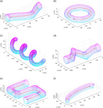
Figure 3(a)–(f) present simulation scenarios for six different environments showing the executed paths by the UAV using our navigation algorithm. Scenarios (a)–(c) considered deformed tunnels with smooth 3D deformations. On contrary, environments with nonsmooth boundaries were handled in scenarios (d)–(f). It was observed that the UAV managed to quickly reach and follow the curvy axis C of the tunnel in cases (a)–(c) keeping a safe distance from the tunnel boundary. In cases like (d)–(f), the UAV could sometimes diverge from moving across C for a short segment when there is a sharp change in the direction of the tunnel boundary. However, it still manages to maintain a safe distance from the wall. These results clearly confirms the performance of our control approach. Even though our algorithm was developed assuming that tunnel walls are smooth, it clearly shows good performance in tunnels with nonsmooth walls and sharp turnings.
Simulation cases of deformed tunnel environments with different shapes considering smooth (a–c) and nonsmooth (d–f) boundaries. (a) A pipe with a smooth bend. (b) A torus-shaped tunnel. (c) A helix-shaped tunnel. (d) A pipe with sharp bends. (e) S-shaped tunnel with sharp edges. (f) A rectangular-shaped tunnel

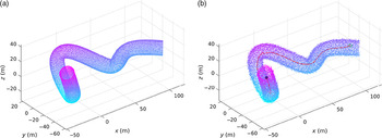
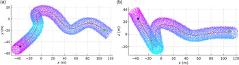
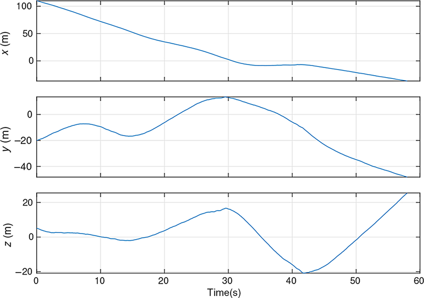
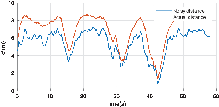
An additional simulation scenario was carried out to investigate the robustness of our method against noisy sensor measurements. The UAV was required to navigate through some pipeline structure as shown in Fig. 4(a). A Gaussian noise was added to the point cloud seen by the sensing module as presented in Fig. 4(b) along with the executed motion by the UAV (different view prospectives are shown in Fig. 5 for better visualization). Figure 6 shows the time evolution of the UAV position  $c(k\delta)$. The actual distance to the tunnel wall during the motion along with the distance based on the noisy point cloud are shown in Fig. 7. It is clear that the motion executed by the vehicle is collision-free. Notice that the vehicle gets close to the tunnel walls around
 $t= 42$ s because of the very sharp bend of the pipe structure at that location. Clearly, these results shows how robust our method is against noisy measurements which is a key feature for practical implementation. The simulations update time was selected as
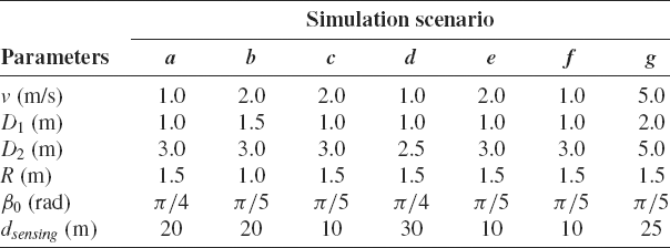
 $\delta = 0.1$ s, and the parameters used for each scenario are provided in Table 1. Animations of all simulation cases with corresponding time plots showing distance to tunnel walls are available at https://youtu.be/r2Add9lctEU.
Simulation scenario g: movement in a complex tunnel environment with noisy sensor observations. (a) A complex pipeline segment. (b) The executed motion based on the noisy point cloud as seen by the UAV sensors

Simulation scenario g: movement in a complex tunnel environment with noisy sensor observations (different camera views). (a) XY view. (b)XZ view

Simulation scenario g: the time evolution of the UAV position (i.e c(t))

Simulation scenario g: the distance between the UAV and the tunnel wall versus time

Parameters used in simulations

5. Implementation with a quadrotor UAV
Our navigation algorithm was developed using a general kinematic model applicable to many vehicles moving in 3D constrained environments. Specific implementation details for quadrotor UAVs including control design and online trajectory generation method description are provided in this section. This is the implementation used in our proof-of-concept experiment.
5.1. Quadrotor dynamics
The kinematic model (1) can be extended to include quadtrotor dynamics. To that effect, we define two coordinate frames, namely an inertial frame  $\{\mathcal{I}\}$ and a body-fixed frame
 $\{\mathcal{B}\}$ attached to the UAV. The origin of
 $\{\mathcal{I}\}$ can be chosen arbitrary in
 $\mathbb{R}^3$, and the origin of
 $\{\mathcal{B}\}$ coincides with the UAV’s center of mass (COM). The attitude of the UAV is expressed as a rotation matrix
 ${\bf R} \subset SO(3): \{\mathcal{B}\}\to \{\mathcal{I}\}$. An associated vector
 $\Omega$ is defined in
 $\{\mathcal{B}\}$ representing the angular velocity of the UAV relative to
 $\{\mathcal{I}\}$. Additionally, Euler angles (roll
 $\phi$, pitch
 $\theta$ and yaw
 $\psi$) or quaternions can also be used to describe the UAV attitude where transformations between the three representations are widely known. Hence, the model from refs. [Reference Hamel, Mahony, Lozano and Ostrowski44,Reference Faessler, Franchi and Scaramuzza45] is used neglecting wind and rotor drag effects which is given by:
 \begin{align}\boldsymbol{\dot{c}}(t) &= {\textbf{V}}(t) \end{align}
 \begin{align}\boldsymbol{\dot{V}}(t) &= -g {\textbf{e}}_3 + T(t) {\bf R}(t) {\textbf{e}}_3 \end{align}
 \begin{align}\dot{{\bf R}}(t) &= {\bf R}(t) \boldsymbol{\hat{\Omega}}(t) \end{align}
 \begin{align}\boldsymbol{\dot{\Omega}}(t) &= {\textbf{J}}^{-1} \left(\boldsymbol{\tau}(t) -\boldsymbol{\Omega}(t) \times {\textbf{J}} \boldsymbol{\Omega}(t)\right)\end{align}
where g is the gravitational constant,  ${\textbf{e}}_3=[0,0,1]^T$,
 $T(t) \in \mathbb{R}^{+}$ is the mass-normalized collective thrust,
 $\boldsymbol{\hat{\Omega}}(t)$ is a skew-symmetric matrix defined according to
 $\boldsymbol{\hat{\Omega}} {\textbf{r}} = \boldsymbol{\Omega} \times {\textbf{r}}$ for any vector
 ${\textbf{r}}\in\mathbb{R}^3$,
 ${\textbf{J}}$ is the inertia matrix with respect to
 $\{\mathcal{B}\}$ and
 $\boldsymbol{\tau}(t) \in \mathbb{R}^3$ is the torques input vector defined in
 $\{\mathcal{B}\}$. The above model can be modified to consider the effects of disturbances as in refs. [Reference Hamel, Mahony, Lozano and Ostrowski44,Reference Faessler, Franchi and Scaramuzza45] for a more robust control design especially when flying near to tunnels boundaries in narrow spaces. We will assume that a low-level attitude controller exists for
 $\boldsymbol{\tau}(t)$ which can achieve any desired attitude
 ${\bf R}_{des}(t)$. Hence, the control design provided in the next subsection considers T(t) and
 ${\bf R}_{des}(t)$ as control inputs. Note that this section adopts the notation of representing vectors and matrices using boldface letters while scalar quantities are represented using light letters.
5.2. Control
A sliding-mode based controller design is presented here for the system (11)–(14) based on the differential-flatness property of quadrotor dynamics. In refs. [Reference Faessler, Franchi and Scaramuzza45,Reference Mellinger and Kumar47], it has been shown that the model (11)–(14) is differentially flat such that it is possible to express the system states and inputs in terms of four flat outputs, namely x, y, z and  $\psi$, and their derivatives.
Consider a smooth reference trajectory to be tracked characterized by  ${\textbf{r}}(t)=[x_r(t), y_r(t), z_r(t), \psi_r(t)]$ with bounded time derivatives. We define trajectory tracking errors according to (i.e. position and velocity tracking errors):
 \begin{equation}{\textbf{e}}_{{\textbf{c}}}(t) = {\textbf{c}}_r(t) - {\textbf{c}}(t),\ {\textbf{e}}_{{\textbf{V}}}(t) = \boldsymbol{\dot{c}}_r(t) - {\textbf{V}}(t)\end{equation}
where  ${\textbf{c}}_r(t)=[x_r(t), y_r(t), z_r(t)]^T$. A sliding variable is then introduced as follows:
 \begin{equation}\boldsymbol{\sigma}(t) = {\textbf{e}}_{{\textbf{V}}}(t) + {\textbf{K}}_1 \tanh(\mu{\textbf{e}}_{{\textbf{c}}}(t))\end{equation}
where  ${\textbf{K}}_1 \in \mathbb{R}^{3\times 3}$ is a positive-definite diagonal matrix,
 $\tanh({\textbf{v}})\in\mathbb{R}^3$ is the element-wise hyperbolic tangent function for a vector
 ${\textbf{v}}\in\mathbb{R}^3$, and
 $\mu>0$. By applying Lyapunov’s direct method, it can be easily found that this choice of a sliding variable will guarantee that both
 ${\textbf{e}}_{{\textbf{c}}}(t)$ and
 ${\textbf{e}}_{{\textbf{V}}}(t)$ asymptotically converge to
 $\textbf{0}=[0,0,0]^T$ when the system trajectories reach the sliding surface
 $\boldsymbol{\sigma}(t)=\textbf{0}$.
By taking the time derivative of (16), one can get:
 \begin{equation}\boldsymbol{\dot{\sigma}}(t) = \boldsymbol{\ddot{c}}_r(t) - \boldsymbol{\dot{V}}(t) + \mu{\textbf{K}}_1 \left({\textbf{e}}_{{\textbf{V}}}(t) \odot sech^2(\mu{\textbf{e}}_{{\textbf{c}}}(t))\right)\end{equation}
where  $sech^2({\textbf{v}})=[sech^2(v_x),sech^2(v_y),sech^2(v_z)]^T$ for some vector
 ${\textbf{v}}=[v_x,v_y,v_z]^T$, and
 ${\textbf{v}}_1\odot {\textbf{v}}_2 \in \mathbb{R}^3$ is defined as the element-wise product between the two vectors
 ${\textbf{v}}_1,{\textbf{v}}_2 \in \mathbb{R}^3$.
Let  ${\textbf{a}}_{cmd}(t) = T(t) {\bf R}(t) {\textbf{e}}_3$ be regarded as a virtual input (i.e. a command acceleration). Now, we propose the following control law:
 \begin{align}{\textbf{a}}_{cmd}(t) =\ & \ddot{{\textbf{c}}}_{r}(t) + g {\textbf{e}}_{3} + \mu{\textbf{K}}_1 \left({\textbf{e}}_{{\textbf{V}}}(t) \odot sech^2(\mu{\textbf{e}}_{{\textbf{c}}}(t))\right)\nonumber \\[5pt]&+ {\textbf{K}}_2 \tanh\left(\mu \boldsymbol{\sigma}(t)\right)\end{align}
where  ${\textbf{K}}_2 \in \mathbb{R}^{3\times 3}$ is a positive-definite diagonal matrix. By substituting (12) and (18) into (17), we obtain the following:
 \begin{equation}\boldsymbol{\dot{\sigma}}(t) = - {\textbf{K}}_2 \tanh\left(\mu \boldsymbol{\sigma}(t)\right)\end{equation}
Equation (19) clearly implies that  $\boldsymbol{\sigma}(t)$ is asymptotically stable. Hence, the control law (18) will force the system trajectories to reach the sliding surface
 $\boldsymbol{\sigma}(t) = 0$ which leads to
 ${\textbf{e}}_{{\textbf{c}}}(t) \to \textbf{0}$ and
 ${\textbf{e}}_{{\textbf{V}}}(t) \to \textbf{0}$ as
 $t \to \infty$.
Now, the input thrust T(t) and the desired attitude  ${\bf R}_{des}=[{\textbf{x}}_{\mathcal{B},des}(t),\ {\textbf{y}}_{\mathcal{B},des}(t),\ {\textbf{z}}_{\mathcal{B},des}(t)]$ can be obtained to achieve (18) and
 $\psi_r(t)$ according to the following:
 \begin{align}{\textbf{z}}_{\mathcal{B},des}(t) &= \frac{{\textbf{a}}_{cmd}(t)}{\|{\textbf{a}}_{cmd}(t)\|} \end{align}
 \begin{align}{\textbf{y}}_{\mathcal{B},des}(t) &= \frac{ {\textbf{z}}_{\mathcal{B},des}(t) \times {\textbf{x}}_{C}(t) }{\|{\textbf{z}}_{\mathcal{B},des}(t) \times {\textbf{x}}_{C}(t)\|} \end{align}
 \begin{align}{\textbf{x}}_{\mathcal{B},des}(t) &= {\textbf{y}}_{\mathcal{B},des}(t) \times {\textbf{z}}_{\mathcal{B},des}(t) \end{align}
 \begin{align}T(t) &= {\textbf{a}}_{cmd}^T(t) {\textbf{R}}(t) {\textbf{e}}_3\end{align}
where  ${\textbf{x}}_{C}(t)$ is defined as:
 \begin{equation}{\textbf{x}}_{C}(t) = [\cos\psi_{r}(t),\ \sin\psi_{r}(t),\ 0]^T\end{equation}
A low-level attitude controller is then used to compute  $\boldsymbol{\tau}(t)$ that can achieve the tracking
 ${\textbf{R}}(t) \to {\textbf{R}}_{des}(t)$.
5.3. Online trajectory generation
In the current implementation, we use  $G_1$ and
 $G_2$ defined in the proposed strategy to determine the direction of progressive motion through the tunnel with minimum jerk trajectories. A computationally efficient solution proposed in ref. [Reference Mueller, Hehn and D’Andrea48] is adopted to generate minimum jerk trajectories for (x,y,z) which can be done independently for each axis. This solution treats the problem as an optimal control problem of a triple integrator system for each output with a state vector
 ${\textbf{s}}(t) = [q(t),\ \dot{q}(t),\ \ddot{q}(t)]$ where
 $q=\{x,y,z\}$, and the jerk
 $\dddot{q}(t)$ is taken as input. Furthermore, to produce minimum jerk solutions, the following cost function is used:
 \begin{equation}J_c = \frac{1}{t_f}\int_{0}^{t_f}\dddot{q}^2(t)dt\end{equation}
where  $t_f$ is the duration of a motion segment. The optimal solution to this problem is ref. [Reference Mueller, Hehn and D’Andrea48]:
 \begin{equation}{\textbf{s}}^*(t) = \left[\begin{array}{c}\displaystyle\frac{k_1}{120}t^5 + \frac{k_2}{24}t^4 + \frac{k_3}{6}t^3 + \frac{\ddot{q}_0}{2}t^2 + \dot{q}_0t + q_0 \\[9pt]\displaystyle\frac{k_1}{24}t^4 + \frac{k_2}{6}t^3 + \frac{k_3}{2}t^2 + \ddot{q}_0 t + \dot{q}_0 \\[9pt]\displaystyle\frac{k_1}{6}t^3 + \frac{k_2}{2}t^2 + k_3 t + \ddot{q}_0\end{array}\right]\end{equation}
where  $(q_0,\ \dot{q}_0, \ddot{q}_0)$ are the components of the initial state vector
 ${\textbf{s}}(0)$, and
 $(k_1,\ k_2,\ k_3)$ are solved for to satisfy the desired final state
 ${\textbf{s}}(t_f)$.
So, at every computation cycle, Eq. (26) is used for each flat output to generate a trajectory segment by setting the boundary conditions as follows:
• Initial state: the current state of the UAV
 ${\textbf{s}}(t_0)$ where $t_0$ is the time at which computation starts or a time ahead to allow for computation latency where the states gets estimated from the trajectory currently being executed.
-
• Final state: the final position
$(x(t_f),y(t_f),z(t_f))$ is set to be $G_1$, and $\psi(t_f)$ is determined such that the vehicle is oriented toward $G_2$ from $G_1$. Furthermore, the final velocity is set to be
(27)where
\begin{equation} (\dot{x}(t_f),\dot{y}(t_f),\dot{z}(t_f))=v_{avg}\frac{G_2 - G_1}{\|G_2 - G_1\|} \end{equation}
$v_{avg}$ is some desired average velocity to keep the UAV moving.


Note that a smooth trajectory for the yaw angle can be generated considering some constant yaw rate with the boundary conditions  $\psi(t_0)$ and
 $\psi(t_f)$.
Another possible implementation for our approach is by relying directly on velocity commands based on (6) in the quadrotor control design without the need for localization. In this case, the command acceleration in (18) can be designed differently such as:
 \begin{equation} \begin{aligned} {\textbf{a}}_{cmd}(t) = {\textbf{K}}_3 \tanh\left(\mu ({\textbf{V}}_{cmd}(t) - {\textbf{V}}(t))\right) + g {\textbf{e}}_{3} \end{aligned} \end{equation}
where  ${\textbf{K}}_3$ is a positive definite gain matrix with some condition related to the bound of
 $||\boldsymbol{\dot{V}}_{cmd}(t)||$, and
 ${\textbf{V}}_{cmd}(t)$ is a filtered version of (6) obtained by applying some smoothing technique.
5.4. Perception pipelines & robust implementation
Good interpretation of sensors measurements is a crucial component for navigation. There are different factors that affect the design of perception systems. Overall system cost, payload capacity, power requirements and required UAV size have great impact on deciding what kind of sensors to use. For example, lightweight 3D LIDARs can be used to provide a sensing solution with a great field of view (FOV) but their sizes and expensive costs need to be considered. Recently, solid-state 3D LIDARs have been developed to a state where they can even provide better solutions for UAVs in terms of size and cost. Alternatively, the use of stereo and depth cameras tends to be popular with small sized UAVs [Reference Sanchez-Rodriguez and Aceves-Lopez49]. However, such depth sensors have narrow FOV, limited range, noisy depth measurements and problems with reflective or highly absorptive surfaces [Reference Naudet-Collette, Melbouci, Gay-Bellile, Ait-Aider and Dhome50]. This adds more challenges on perception algorithms development to produce reliable and robust solutions. In this section, we provide two possible perception pipelines based on the suggested navigation approach with different computational costs. The goal of both algorithms is to determine an estimate of the gravity centers  $G_1$ and
 $G_2$ described by our navigation strategy.
5.4.1. Simple algorithm
The first algorithm is targeted toward vehicles with very limited computational power. It has basic steps to allow for low-latency perception at the expense of being prone to some situations where the vehicle may need to hover and rotate to be able to continue progressing through the tunnel.
The recent available point cloud from onboard sensors are processed at certain rate according to the following. Consider that all calculations are made in a camera-fixed frame  $\{\mathcal{C}\}$ which has a known transformation relative to the body-fixed frame. Note that we will use the notation
 ${}^{\mathcal{C}}{\textbf{p}}$ to represent vectors expressed in the
 $\{\mathcal{C}\}$ frame. The first step is to downsample the raw point cloud to reduce the computational cost. Then, the nearest k points to the current UAV position
 ${}^{\mathcal{C}}{\textbf{c}}$ are determined where
 ${}^{\mathcal{C}}{\textbf{c}}$ is the UAV’s COM expressed in the camera frame and k can be chosen arbitrary. A geometric average
 ${}^{\mathcal{C}}\bar{G}_a$ is then calculated for the nearest neighbors points. Let
 ${}^{\mathcal{C}}{\textbf{i}}_{a} = {}^{\mathcal{C}}\bar{G}_a - {}^{\mathcal{C}}{\textbf{c}}$ be the vector toward
 ${}^{\mathcal{C}}\bar{G}_a$. Then, we compute
 $\alpha$ which is the angle between the current velocity vector and
 ${}^{\mathcal{C}}{\textbf{i}}_{a}$ using:
 \begin{equation} \alpha = \cos^{-1}\left(\frac{{}^{\mathcal{C}}{\textbf{i}}_{a}\cdot{}^{\mathcal{C}}{\textbf{V}} }{\|{}^{\mathcal{C}}{\textbf{i}}_{a}\| \|{}^{\mathcal{C}}{\textbf{V}}\|}\right)\end{equation}
Another vector  ${}^{\mathcal{C}}{\textbf{i}}_{b}$ is obtained next by rotating
 ${}^{\mathcal{C}}{\textbf{V}}$ by
 $-\alpha$ in the plane containing both
 ${}^{\mathcal{C}}{\textbf{V}}$ and
 ${}^{\mathcal{C}}{\textbf{i}}_{a}$. Hence, a second point
 ${}^{\mathcal{C}}\bar{G}_b$ can be computed as the gravity center of the tunnel wall points in the direction of
 ${}^{\mathcal{C}}{\textbf{i}}_{b}$. Similarly, another two points
 ${}^{\mathcal{C}}\bar{G}_c$ and
 ${}^{\mathcal{C}}\bar{G}_d$ can be obtained associated with rotating the vector
 ${}^{\mathcal{C}}{\textbf{V}}$ by angles
 $\beta$ and
 $-\beta$, respectively, where the relation between
 $\alpha$ and
 $\beta$ is defined in our strategy. Hence,
 ${}^{\mathcal{C}}G_1$ and
 ${}^{\mathcal{C}}G_2$ are computed according to:
 \begin{equation} \begin{array}{ll} {}^{\mathcal{C}}G_1 = 0.5({}^{\mathcal{C}}\bar{G}_a + {}^{\mathcal{C}}\bar{G}_b), & {}^{\mathcal{C}}G_2 = 0.5({}^{\mathcal{C}}\bar{G}_c + {}^{\mathcal{C}}\bar{G}_d) \end{array}\end{equation}
which can then be transformed to the inertial frame  $\{\mathcal{I}\}$ to get
 $G_1$ and
 $G_2$.
5.4.2. Complete & robust algorithm
The proposed strategy in this work has shown good results in simulations using sensors with wide FOV (e.g. LIDAR or multiple cameras). Based on experimental observations, additional layers can be added to the overall algorithm to deal with some practical aspects when using sensors with narrow FOV for increased robustness. The algorithm can be summarized using the following steps whenever new measurements arrive or at some other update rate slower than sensors measurements rate:
1. Downsample the raw point cloud to obtain
$\mathcal{W}_s$ for improved computational performance.-
2. Select N points
$({}^{\mathcal{C}}{\textbf{O}}_1, {}^{\mathcal{C}}{\textbf{O}}_2,\cdots,{}^{\mathcal{C}}{\textbf{O}}_N)$ ahead of the vehicle position according to (8) at distances $D_1, D_2, \cdots, D_N$ where $D_1 < D_2 < \cdots D_N$ (rather than just 2 as suggested earlier). -
3. Filter the downsampled point cloud
$\mathcal{W}_s$ around each point ${}^{\mathcal{C}}{\textbf{O}}_i$ obtained from the previous step to extract the corresponding sections $\mathcal{O}_i \subset \mathcal{W}_s$ as defined in (10) with some tolerance $\epsilon > 0$. -
4. For each filtered section
$\mathcal{O}_i$, compute the geometric mean ${\textbf{g}}_i \in \mathbb{R}^3$ of all the points (i.e. the centroid) and add those centroids to a list $\mathcal{L}$ such that $\mathcal{L} = \{{\textbf{g}}_1, {\textbf{g}}_2, \cdots, {\textbf{g}}_N\}$. -
5. Compute the minimum distance from each point in
$\mathcal{L}$ to the downsampled point cloud $\mathcal{W}_s$, and flag it as valid if $d_{g,i} > d_{safe}$ where
Otherwise, flag the point as invalid.
\begin{equation*} d_{g,i} = {\textrm{argmin}}_{{\textbf{p}}_i \in \mathcal{O}_i} \|{\textbf{g}}_i - {\textbf{p}}_i\| \end{equation*}
-
6. For each invalid point in
$\mathcal{L}$, compute a safer position by moving it away from the nearest neighbors in $\mathcal{W}_s$ in the direction of the average estimated surface normals at the nearest neighbors with some distance larger than $ d_{safe} - d_{g,i}$. -
7. Add the adjusted points to
$\mathcal{L}$, and flag them as valid or invalid according to step 4. -
8. Iterate through
$\mathcal{L}$ to obtain the closest two valid points as ${}^{\mathcal{C}}G_1$ and ${}^{\mathcal{C}}G_2$ which can then be transformed from the sensors frame to obtain $G_1$ and $G_2$. -
9. If the number of valid points in
$\mathcal{L}$ is less than 2, increment some counter i which was initialized with 0. Otherwise, reset $i = 0$. If the counter i reaches some predefined threshold k, terminate.


6. Proof-of-Concept experiments
6.1. Experiments setup
We conducted different experiments to validate our navigation method using a quadrotor UAV with two different sensors configurations. Three experimental cases are given in this section showing flights through deformed tunnel-like structures made in the lab using our suggested method. In all experiments, the sides of the tunnel were nonsmooth and curved, and the ceiling structure was not even. The first case deals with a deformed tunnel with approximately  $2.4\,\text{m}$ width,
 $2\,\text{m}$ height and
 $5.2\,\text{m}$ in length. The last two experiments were carried out using a different structure where the tunnel is more curvy in the middle. Also, it gets narrower toward the end where it becomes more challenging to fly such that it has a
 $2.3\,\text{m}$ width and
 $3\,\text{m}$ height at the beginning which reduces to
 $1.5\,\text{m}$ width by
 $1.4\,\text{m}$ in height toward the end for a total length of approximately
 $6\,\text{m}$. In the last case, the tunnel floor was elevated at the beginning by adding a blocking obstacle which was
 $0.9\,\text{m}$ high.
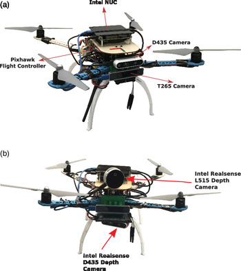
A custom-made quadrotor is used in the experiments which is shown in Fig. 8. It is equipped with a Pixhawk Flight Controller Unit (FCU) which contains a 32-bit Microcontroller Unit (MCU) running the PX4 firmware in addition to a set of sensors including gyroscopes, accelerometers, magnetometer and barometer. The open-source PX4 software stack handles the low-level attitude stabilization and implements an Extended Kalman Filter (EKF) that fuses IMU data and visual odometry to provide an estimate of the quadrotor states (i.e. position, attitude and velocity). To allow for a fully autonomous operation, our UAV is equipped with an onboard computer connected with cameras for localization and sensing. Hence, all computations needed to implement our navigation method can be done onboard. A powerful onboard computer (Intel NUC), with an Intel Core i5-8259U CPU @ 2.30GHz, is used to implement the overall navigation stack. Intel RealSense tracking camera T265 is used for visual localization, and Intel RealSense D435/L515 depth cameras are used to detect the tunnel surface. The T265 module provides monochrome fisheye images with a great FOV, and it contains an IMU and a Vision Processing Unit (VPU) to implement onboard visual SLAM. The D435 camera provides depth information as 3D point clouds, and it has a Depth FOV of ( $87^\circ\pm3^\circ\ \text{Horizontal}\ \times\ 58^\circ\pm1^\circ\ \text{Vertical}\ \times\ 95^\circ\pm3^\circ\ \text{Diagonal}$) and a maximum range of approx.
 $10\,\text{m}$. However, a shorter range could be used in practice as the D435 depth data are more noisy for points further than 3 m. Note that it is possible to use only the D435 camera to perform both localization and tunnel surface detection on the onboard computer. The RealSense L515 camera provides more accurate depth data with accuracy of about 5–14 mm for a range of
 $9\,\text{m}$ since it is based on solid-state LIDAR technology. However, it has a narrower FOV of
 $70^\circ\ \times\ 55^\circ \ (\pm3^\circ)$. Figure 8 shows the two sensors configuration used in the three experiments where the one on top was used in the first case and the other configuration was used in the other two cases. The second configuration provides a wider FOV by combining the depth data from both the D435 and L515 depth cameras, which are oriented differently, after applying proper transformations.
The quadrotor used in the experiments with different sensor configurations. (a) Single depth camera. (b) Two depth cameras (wider FOV)

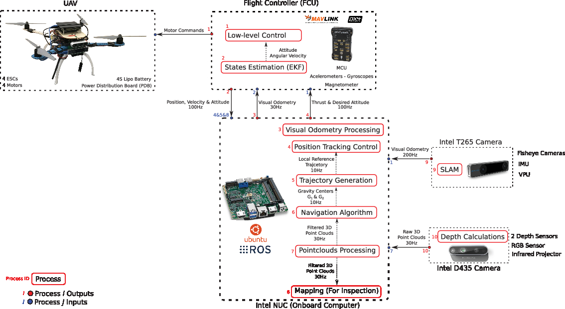
The Robot Operating System (ROS) framework was adopted to implement the overall navigation software stack as connected nodes (i.e. simultaneously running processes) where each node handles a specific task. A UAV control node implements the trajectory tracking controller described in Section 5.2 to generate thrust and attitude commands for the low-level attitude controller at  $100\,\text{Hz}$. These commands are sent to the flight controller unit through a link with the onboard computer (over USB) using the MAVLink messaging protocol through MAVROS library. The received visual odometry from the T265 camera is also sent to the FCU to be fused with IMU data through an extended Kalman filter. Also, camera nodes are used to process received 3D point clouds from the depth cameras to make them available for the other nodes with an update rate of
 $30\,\text{Hz}$. The proposed simpler algorithm described in Section 5.4.1 was used in the first experiment, and the more robust approach proposed in Section 5.4.2 was used in the other two cases. These algorithms were running at 2–10 Hz update rates, and they were implemented in C++ using useful tools from the Point Cloud Library (PCL) to handle point clouds processing in a computationally efficient way. A downsampling filter using PCL VoxelGrid is applied to the 3D point clouds to reduce the computational burden combined with some other filtering processes such as considering measurements that are within 5 m or less. A further processing is applied to assemble a single point cloud from all depth sensors if multiple are used by applying proper transformations from the sensors’ frames to the vehicle’s body-fixed frame. The obtained points
 $G_1$ and
 $G_2$ from the previous algorithms are used to generate reference trajectories to be sent to the UAV control node where the approach described in Section 5.3 was used in the first case. In the last two cases, the similar idea was used but with slower straight motion trajectories based on trapezoidal velocity profile to deal with the very narrow flying space (i.e. only (26) was implemented differently). Note that generating minimum jerk trajectories is recommended to produce less jerky motions; however, some corridor constraints may need to be considered to refine the result of (26) when flying in very narrow spaces similar to what was done in ref. [Reference Mellinger and Kumar47].
A description of the overall hardware and software architecture of our system is shown in Fig. 9.
Hardware and Software Architecture of our UAV system

6.2. Results
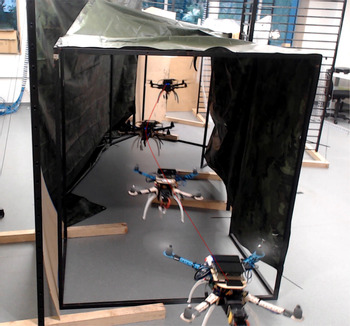
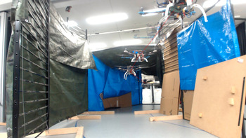
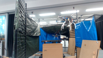
A video of the conducted experiments is available at https://youtu.be/r2Add9lctEU. Snapshots of the motion at different time instants are shown in Figs. 10, 11 and 12 for the three cases where a line connecting positions at each time instant was added for visualization purposes only (i.e. it is not the actual path). Additionally, visualizations of the sensors feedback along with the results of the implemented perception pipelines at some specific moments during the flights are shown in Figs. 13 and 14.
Snapshots of the UAV position during movement for case 1

Snapshots of the UAV position during movement for case 2

Snapshots of the UAV position during movement for case 3

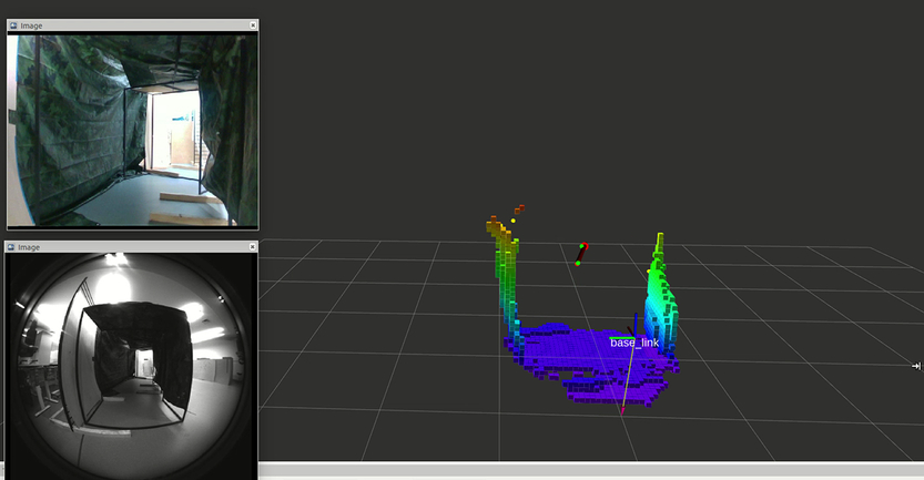
A fraction of the tunnel wall sensed at motion start along with cameras feedback for case 1

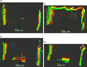
Robust perception pipeline visualization for cases 2 and 3

Figure 13 shows the detected patch of the tunnel surface, the vector directing from  $G_1$ to
 $G_2$ and cameras feedback at the initial time for the first experiment. In that figure, the current position of the UAV is indicated by the axes named ‘base_link’ while the red arrow is at
 $G_1$ and directing toward
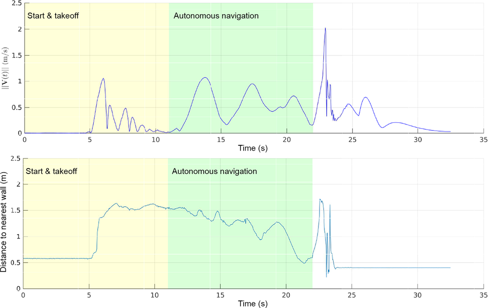
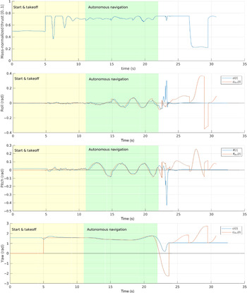
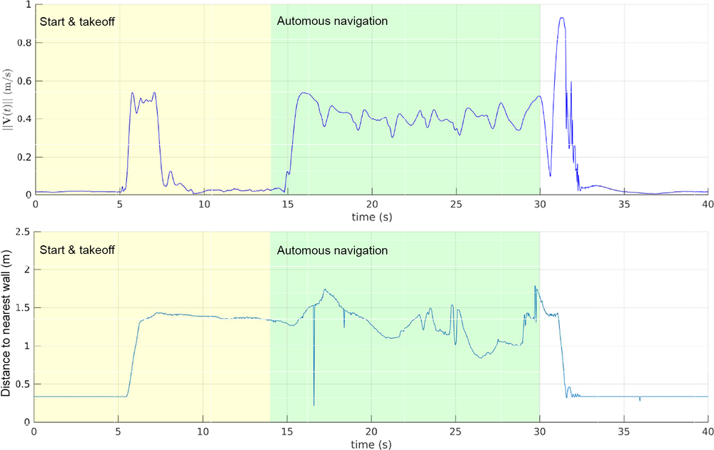
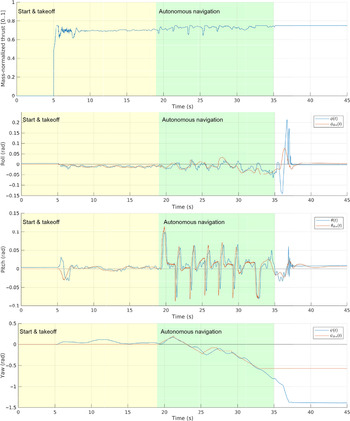
 $G_2$ as described in Section 5.3. Notice that an online mapping algorithm was also performed onboard in this case to provide a map of the tunnel for visualization purposes only. The velocity of the quadrotor during the flight and the distance to tunnel walls are shown in Fig. 15. Moreover, the applied control inputs along with the vehicle’s attitude is shown in Fig. 16. The mass-normalized collective thrust is further normalized to be within [0,1] as required by PX4. For safety purposes, the maximum value of the input thrust was limited to
 $0.75$. Different regions are highlighted on the figures corresponding to the mode of operation. Initially, sensors and safety checks are done in order to arm the drone before performing a takeoff to some predefined altitude. Then, the vehicle switches to autonomous mode where the suggested navigation strategy is applied. Once a terminating condition is detected, the vehicle goes out of the autonomous mode where the control commands are no longer being used in order to land.
UAV velocity and distance to closest point versus time for case 1

Input mass-normalized collective thrust and attitude commands versus time for case 1

It can be seen from the video and Fig. 10 that the vehicle manages to maintain its movement along the tunnel curvy axis in the first experiment until it reaches the tunnel open end where it goes closer to one of the sides (as can be seen from Fig. 15). It can also be observed that the nonsmooth tunnel surface results in  $D_1$ and
 $D_2$ being dynamic during the motion when using the approach described in Section 5.4.1. This counts as a reaction to any bumps on the surface close to the UAV to achieve a collision-free motion. The computational latency using this simple approach was less than
 $1\,\text{ms}$ using the mentioned mini computer. It was observed in this experiment that using a depth sensor with small FOV which detects only a small patch of the tunnel surface can be very challenging. This explains the behavior near the end of the motion due to the tunnel being open and the depth measurements being filtered to only consider information within 2 m or less. In that case, a stopping policy was applied at the end to yaw away from the tunnel side and land immediately. Another possible policy to apply in these situations is to hover and perform a yaw rotation to proceed the movement using that suggested simple perception approach. One of the used methods in practice to have a wider 3D FOV is to use a mechanism to rotate the sensor at some frequency during the motion (for example, see refs. [Reference Kang and Doh51,Reference Kownacki52]). It is also possible to integrate more sensors by combining vision-based sensors with LIDARs depending on the application requirements and the environment conditions; however, this will reflect on the system overall cost, payload and power requirements.
The observations from the first case motivated the design of the robust algorithm given in Section 5.4.2 which was applied in the next two experiments. Only three points were computed (i.e.  $N=3$) corresponding to
 $D_1 = 1.25\,\text{m}$,
 $D_2 = 1.5\,\text{m}$ and
 $D_3 = 1.75\,\text{m}$. Also, the sections extraction tolerance was selected as
 $\epsilon=0.1\,\text{m}$, and the safety margin was
 $d_{safe}=0.45\,\text{m}$.
Different scenarios based on depth measurements are shown in Fig. 14 where all points in the list  $\mathcal{L}$ are represented with spherical markers with different colors. Also, corresponding extracted sections
 $\mathcal{O}_1$,
 $\mathcal{O}_2$ and
 $\mathcal{O}_3$ from the point cloud are highlighted in different colors (green, yellow and orange respectively). Yellow markers represent valid points obtained directly from step 4 as in Fig. 14(a); hence, steps 6–7 were not executed at that computation cycle. Figure 14(b) shows a case where all computed points were invalid (red markers), and valid new points (orange markers) were obtained after performing steps 6–7. This may happen whenever the vehicle senses only a fraction of a certain side without seeing the side in the opposite direction (the lower part of the tunnel is not detected in that case). Similar case is shown in Fig. 14(c) where the upper part of the tunnel is not within the sensors’ FOV at that point. As a result, the geometric means will be closer to the detected portion. However, it is clear from the experiments that the proposed approach managed to handle such cases very well. Further case is shown in Fig. 14(d) where one of the new obtained points after applying step 6 remains invalid (blue marker). The computational latency when steps 6–7 are not executed was less than
 $5\,\text{ms}$. Otherwise, the latency was less than
 $70\,\text{ms}$ which can be hugely improved by estimating the surface normals for only the closest fraction of the point cloud rather than the whole downsampled cloud as was done in the experiments. The surface normals estimation is computationally more expensive than the other steps; however, the overall computational performance is still very low compared to path planning-based methods.
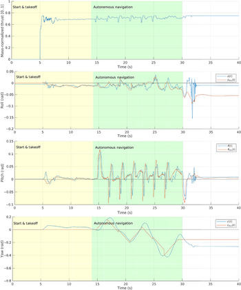
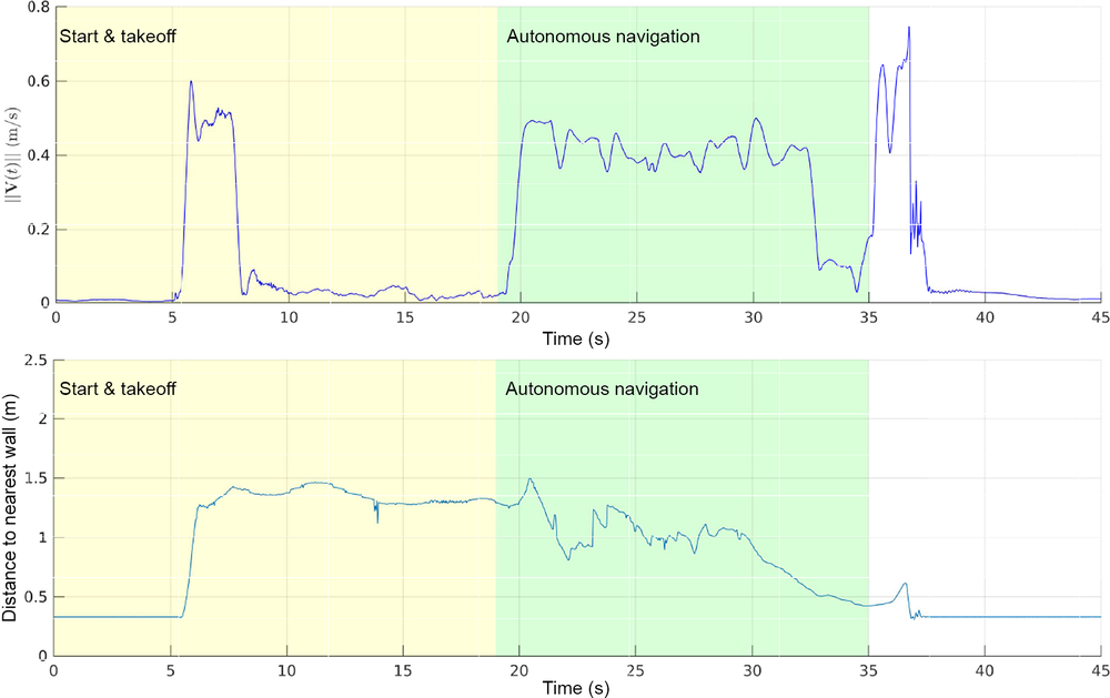
The quadrotor’s velocity, minimum distance to tunnel walls and control inputs are shown in Figs. 17–20 for the two cases. The velocity of the reference trajectory was designed to be around  $0.4\,\text{m/s}$ which can be seen from the actual velocity plot. The minimum distance to tunnel walls was computed based on the sensors point clouds which might not be a good estimate of the actual distance at some points. However, these plots indicate that the vehicle maintained a safe distance during the flights. Thus, these experiments validate the performance of the suggested tunnel navigation strategy.
UAV velocity and distance to closest point versus time for case 2

Input mass-normalized collective thrust and attitude commands versus time for case 2

UAV velocity and distance to closest point versus time for case 3

Input mass-normalized collective thrust and attitude commands versus time for case 3

7. Conclusion
This work presented a computationally light method for UAVs to allow autonomous collision-free navigation in unknown tunnel-like environments. It relies on light processing of sensors’ measurements to guide the UAV along the tunnel axis. A general 3D kinematic model is used for the development which extends the applicability of our method to different UAV types and autonomous underwater vehicles navigating through 3D tunnel-like environments. Several simulations were performed to validate our method considering tunnels with different structures using a realistic sensing model. Robustness against noisy sensors measurements was also investigated in simulation. Moreover, we provided implementation details for quadrotor UAVs including control design based on sliding mode control technique and differential-flatness property of quadrotor dynamics. Experimental validation was done by flying through tunnel-like structures built in the laboratory where all computations needed by our navigation stack were done onboard. Overall, the obtained results from simulations and the practical implementations show how well our navigation method works in unknown tunnel-like environments.
Acknowledgements. This work was supported by the Australian Research Council. Also this work received funding from the Australian Government, via grant AUSMURIB000001 associated with ONR MURI grant N00014-19-1-2571.
Conflicts of Interest. The author(s) declare none.
Cite this article: T. Elmokadem and A. V. Savkin, “A method for autonomous collision-free navigation of a quadrotor UAV in unknown tunnel-like environments”, Robotica. https://doi.org/10.1017/S0263574721000849