I. INTRODUCTION
Due to their outstanding mechanical properties, such as both high strength and high modulus, carbon fibers are attractive reinforcing materials in fabrication of high performance composites. Reference Chand1 In addition to the excellent mechanical properties, in many fields, such as aerospace engineering and thermal protection system (TPS), the infrared emissivity properties of carbon fibers are also very important in service. The infrared emissivity properties affect energy transformation, temperature distribution, and thermal radiation efficiency of materials. In recent years, as the thermal radiator, carbon fibers have also been widely used in the domestic heating fields. Those application fields all need to know the infrared emissivity properties of carbon fibers, as well as the composites reinforced by carbon fibers. Reference Wang, Cheng, Xiang, Zhang and Zhang2,Reference Alfano, Scatteia, Cantoni and Balat-Pichelin3
In service, high temperature is a severe challenge for carbon fibers. Reference Mei, Cheng, Zhang, Luan and Zhang4,Reference Ma, Xu, Zhang, Cheng, Nie and Li5 The high temperature treatments improve the graphitization degree of carbon fibers. The microstructure changes in carbon fibers will finally affect the thermal radiation behavior. In carbon-fiber-reinforced ceramic matrix composites, pyrolytic carbon (PyC) is usually used as the interface between carbon fibers and ceramic matrix to adjust interfacial bonds. Reference Cheng, Xu, Zhang and Yin6 Straight carbon nanotubes (CNTs) as another attracting material have been applied to improve the performance of carbon fibers in recent years. Reference Song, Li, Li, Li and Ren7,Reference Qian, Greenhalgh, Shaffer and Bismarck8 PyC or CNT coating changes the surface microstructure of carbon fibers and affects the infrared emissivity properties of carbon fibers. The response of the heat-treated and the coated carbon fibers to high temperature is the function of the relevant thermophysical properties. For engineering design and interpretation of performance data, the infrared emissivity properties should be carefully characterized in terms of parameters such as thermal history, coating microstructure, and coating thickness.
In the present study, the effects of heat treatment and PyC or CNT coating on the infrared emissivity properties of carbon fibers are investigated. For comparison, the as-received carbon fibers are also tested here. Many analyses and discussions are focused on the infrared emissivity properties referred to the evolution of microstructure under different treatments.
II. MATERIALS AND EXPERIMENTS
A. Preparation of materials
T300™ carbon fibers with a diameter of about 6 μm from Toray (Tokyo, Japan) were used in the study. The heat treatment of the as-received carbon fibers was carried out at 1873 and 2073 K for 2 h under Ar atmosphere. The samples were respectively denoted as “1873 K-HT” and “2073 K-HT.” PyC coating was deposited on carbon fibers by chemical vapor deposition (CVD) at 960 °C. In the CVD process, propylene (C3H8) was used as the precursor mixed with a dilution gas of argon. The deposition time was 100 and 200 h, and the coating thickness was 0.5 and 1.0 μm. The samples with 0.5 and 1.0 μm PyC coating were respectively denoted as “CF/PyC-0.5” and “CF/PyC-1.0” in the figures. For preparing CNT coating, carbon fibers were soaked in acetone with 1.5 wt% Ni(NO3)2•6H2O for 12 h and then dried in air. Subsequently, the samples were loaded into a reactor for CNT growth and heated to 1000 °C under Ar atmosphere. Methane (CH4) was fed as the carbon source and the flow rate was 16 L/h and Ar was used as the diluent gas and the flow rate was 120 L/h. The growth time was 2 h. In the figures, “CF/CNTs” denoted the carbon fibers with CNT coating.
B. Apparatus and measurements
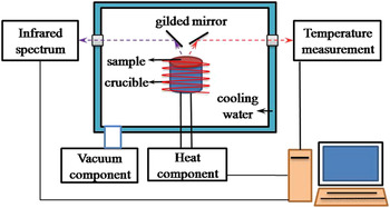
The infrared spectral emissivity of samples was measured by a special apparatus, which could provide high vacuum and high temperature in the tests. As seen in Fig. 1, the apparatus was mainly composed of four parts: vacuum component; temperature monitored component; heating component; and infrared spectrum measurement component. When the sample was heated to the desired temperature, the thermal radiation signal was transferred to Fourier Transform Infrared Spectrometer (FTIR) by a series of gilded mirrors. A liquid nitrogen-cooled mercury–cadmium–telluride (MCT) detector was used to detect the infrared emissivity spectrogram in the wave length range 6–15 μm.
Schematic diagram of the infrared emissivity measurement system.

According to the definition of thermal radiation, the total emissivity of materials in the wave length range from λ1 to λ2 can be calculated through the spectral emissivity ελ using the integral method Reference Modest9 :
 $${\varepsilon _T} = {{\int_{{{\rm{\lambda }}_1}}^{{{\rm{\lambda }}_2}} {{{\rm{\varepsilon }}_{\rm{\lambda }}}{E_{{\rm{b\lambda }}}}{\mathop{\rm {\it{d}}}\nolimits} {\rm{\lambda }}} } \over {\int_{{{\rm{\lambda }}_1}}^{{{\rm{\lambda }}_2}} {{E_{{\rm{b\lambda }}}}} {\mathop{\rm {\it{d}}}\nolimits} {\rm{\lambda }}}} = {{\mathop\sum\limits_{{{\rm{\lambda }}_1}}^{{{\rm{\lambda }}_2}} {{{\rm{\varepsilon }}_{\rm{\lambda }}}{E_{{\rm{b\lambda }}}}\Delta {\rm{\lambda }}} } \over {\mathop\sum\limits_{{{\rm{\lambda }}_1}}^{{{\rm{\lambda }}_2}} {{E_{{\rm{b\lambda }}}}\Delta {\rm{\lambda }}} }}{\rm{\quad,}}$$
here E bλ represents the thermal radiation intensity of the blackbody at wave length λ and temperature T.
The surface morphology of samples and the coating thickness were observed by Scanning Electron Microscopy (SEM, HITACHI S4700, Japan). Laser Raman spectroscopy was used for assessing the carbon fibers' microstructure before and after heat treatment.
III. RESULTS AND DISCUSSIONS
A. Effect of heat treatment
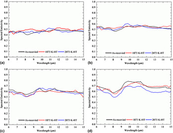
Figure 2 shows the spectral emissivity of the as-received and the heat-treated carbon fibers as a function of wave length. From Figs. 2(a)–2(d), the fluctuation of spectral emissivity was improved, which meant that the wave length sensitivity of spectral emissivity in samples was raised with increasing test temperatures. At 1273, 1473, and 1673 K, the spectral emissivity curves of three types of samples almost overlapped each other and presented no distinct differences. With further increasing test temperature up to 1873 K, the heat treatment obviously changed the spectral emissivity of carbon fibers. The spectral emissivity of the 2073 K-treated carbon fibers was obviously lower than that of two other ones. The differences between the as-received and the 1873 K-treated ones were still indistinct. The results indicated that the heat treatment at 2073 K had greater effects on the spectral emissivity of carbon fibers than that at 1873 K.
Spectral emissivity of the as-received and the heat-treated carbon fibers at different test temperatures: (a) 1273 K; (b)1473 K; (c)1673 K; (d) 873 K.

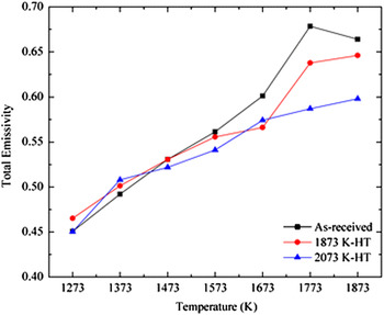
Figure 3 presents the total emissivity of carbon fibers before and after heat treatment. When the test temperatures were below 1673 K, the total emissivity of the heat-treated samples did not vary evidently. The results were consistent with those in the spectral emissivity and indicated that the heat treatment has few effects on the infrared emissivity properties of carbon fibers. At and above 1673 K, the total emissivity of the as-received carbon fibers presented the maximum, following by the 1873 K-treated and the 2073 K-treated ones. In other words, the heat treatment at 1873 and 2073 K successively reduced the total emissivity of carbon fibers under high temperatures. The phenomenon referred to the microstructure evolution of carbon fibers during the heat treatment. This relationship was discussed further in the following paragraphs.
Total emissivity of the as-received and the heat-treated carbon fibers as a function of test temperature.

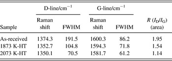
Table I lists the Raman parameters of carbon fibers before and after heat treatment to assess the microstructural evolution in carbon fibers. The D-line presented the disordered structure and the G-line presented the ordered structure in carbon materials. Reference Endo, Nishimura, Kim, Hakamada, Matushita, Dresselhaus and Dresselhaus10 The characteristic R (I D/I G) was defined as the ratio of the integrated intensity of D-line to that of G-line, the lower R value, the higher graphitization degree. After heat treatment, R was reduced from 1.95 to 1.14 and the FWHM of the both first order lines D and G became narrow successively. Those changes in Raman parameters illustrated that the heat treatment enlarged the graphite crystallites and improved the graphitization degree in carbon fibers.
Raman parameters of the as-received and the heat-treated carbon fibers.

B. Effect of PyC and CNT coating
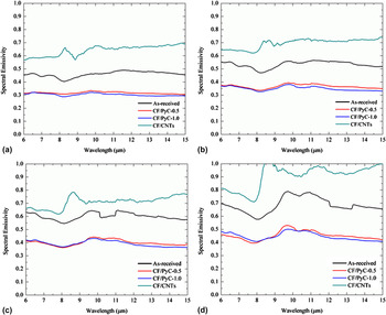
The spectral emissivity of the as-received carbon fibers and the ones with PyC or CNT coating at four temperatures is shown in Fig. 4. In the present study, the infrared spectral emissivity of carbon fibers with PyC coating was obviously lower than that of the as-received ones in 6–16 μm, but the higher value for the CNT-coated ones. The infrared emissivity curves of carbon fibers with 0.5 and 1.0 μm PyC coating nearly overlapped each other in the test temperature range, which meant that the coating thickness from 0.5 to 1.0 μm had almost no influence on the infrared emissivity of the PyC-coated carbon fibers.
Spectral emissivity of the as-received and the coated carbon fibers at different test temperatures: (a) 1273 K; (b)1473 K; (c)1673 K; (d)1873 K.

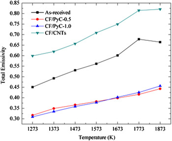
Figure 5 shows the total emissivity of the as-received and the coated carbon fibers as a function of temperature. For the PyC-coated carbon fibers, the total emissivity of carbon fibers with 0.5 μm coating increased from 0.32 to 0.47, while that with 1.0 μm coating increased from 0.30 to 0.48 gradually. Clearly, the changes in the total emissivity of the PyC-coated samples caused by the coating thickness were very limited, which was consistent with results in the spectral emissivity. The total emissivity of the PyC-coated carbon fibers decreased about 30% at 1273 K in comparison with that of the as-received ones, and the maximum drop rate reached 38% at 1773 K. In contrast to the as-received carbon fibers, the total emissivity of the CNT-coated carbon fibers increased about 35% and this increase rate kept almost constant in the test temperature range. Consequently, the infrared emissivity properties of carbon fibers were greatly changed by the coating on the carbon fibers, decreasing by the PyC coating and increasing by the CNT coating.
Total emissivity of the as-received and the coated carbon fibers as a function of test temperature.

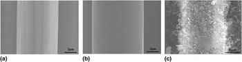
The surface morphologies of the as-received and the coated carbon fiber are shown in Fig. 6. For the as-received carbon fiber as seen in Fig. 6(a), there were many obvious grooves uniformly distributed along with the longitudinal direction of the carbon fiber, which related to the spinning process of preparing fibers. Reference De Pauw, Reznik, Kalhöfer, Gerthsen, Hu and Hüttinger11 After PyC deposition, the grooves were filled and the sample surface was smoother than that of the as-received one as shown in Fig. 6(b). By adjusting the deposition time from 100 to 200 h, the coating thickness varied from 0.5 to 1.0 μm. In Fig. 6(c), the CNTs covered the whole carbon fiber surface. The random distribution and the random orientation of CNTs formed a rough surface porous and skeleton-like structure.
SEM images of the as-received and the coated carbon fiber: (a) the as-received carbon fiber; (b) the PyC-coated carbon fiber; (c) the CNT-coated carbon fiber.

C. Effect mechanism
When the carbon fibers were heat treated under high temperatures, the polycrystalline graphite in the carbon fibers contacted with each other and grown up as proved in Table I. In the meantime, the graphitization degree was improved and the amount of the dangling bonds at the edge of the graphite crystallites was reduced. According to the quantum mechanics theory and the infrared radiation theory, the thermal radiation of materials mainly stemmed from the interaction of free carriers with crystal lattices. Reference Modest9,Reference Siegel and Howell12 Increasing the graphitization degree reduced the scattering of free carriers with the crystal lattices and lowered the infrared emissivity properties of carbon fibers. The reduction in the amount of the dangling bonds also weakened the thermal radiation ability of carbon materials. When the infrared emissivity tests were carried out below 1673 K, the interaction of free carriers with crystal lattices and with dangling bonds was mild in carbon fibers. Reference Gao, Zhao, Luo, Tong and Xu13 The effects of the microstructure evolution in carbon fibers caused by the heat treatment on the infrared emissivity were limited. Therefore, the spectral emissivity and the total emissivity between the as-received and the heat-treated carbon fibers were close to each other. Above 1673 K, the interaction of free carriers with crystal lattices and with dangling bonds enhanced. In this case, the microstructure evolution in the heat treatment had great influence on the infrared emissivity properties of carbon fibers, causing obvious decrease. Heightening heat treatment temperature from 1873 to 2073 K, the graphite crystallites further grown up and the amount of dangling bonds further reduced. The formation of the network structure reduced the amount of dangling bonds in carbon fibers and weakened the thermal radiation ability. As a result, the infrared emissivity of carbon fibers showed continuous reduction with the heat treatment temperature increasing from 1873 to 2073 K, especially at high test temperatures.
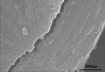
When the carbon fiber surface was covered by PyC coating, it became smooth, as seen in Figs. 6(a) and 6(b). However, the changes in the surface morphology were in nanoscale, which was one order of magnitude lower than the infrared wave length. The effects of the surface morphology changes on the infrared emissivity of carbon fibers could be ignored. Therefore, it could conclude that the differences in the infrared emissivity mainly stemmed from the microstructural differences between carbon fibers and PyC coating. The polyacrylonitrile (PAN)-based carbon fibers utilized in this study were mainly composed of polycrystalline graphite and amorphous carbon. Further studies indicated that lamellar graphite in the skin region was parallel to the fiber surface, and turbostratic graphite in the core region randomly distributed. Reference Peebles14 Previous studies identified that the infrared emissivity properties of graphite crystallites with lamellar structures parallel to the surface were lower than that of one perpendicular to the surface by a factor of 2 to 3. Reference Wang, Cheng, Mei, Zhang and Zhang15 In the as-received carbon fibers, the skin region was very thin, so their infrared emissivity properties were mainly controlled by the turbostratic graphite in the core region. The free orientation of turbostratic graphite in the core region endued carbon fibers with high infrared emissivity properties. In contrast, lamellar graphite was the major component in PyC coating and was parallel to the surface as seen in Fig. 7. Reference Reznik and Hüttinger16 The lamellar structure endued PyC with the relatively low infrared emissivity compared with carbon fibers with turbostratic graphite in the core region. The infrared emissivity of the PyC-coated carbon fibers was controlled and reduced by the PyC coating. Increasing the PyC coating thickness from 0.5 to 1.0 μm did not changed the surface microstructure, thus there were no obvious changes in the infrared emissivity properties. It could conclude that microstructural differences between carbon fibers and PyC coating were the main reason to cause the decrease in the infrared emissivity of the PyC-coated carbon fibers. After preparing CNT coating, the carbon fiber surface was covered by the porous and skeleton-like structure as seen in Fig. 6(c). The special structure of CNTs on the carbon fiber surface produced large amounts of new faces and points. When the electromagnetic waves of the thermal radiation propagated in this skeleton-like structure, they were multiply reflected and scattered by these new faces and points. This process would increase the absorption of the radiative energy. According to Kirchhoff's laws, the high absorption meant the high emissivity. Therefore, the porous and skeleton-like structure CNTs improved the infrared emissivity properties of the CNT-coated carbon fibers.
Cross-sectional image of PyC.

IV. CONCLUSIONS
The present study clarified the infrared emissivity properties of carbon fibers as a function of the heat treatment, PyC, and CNT coatings, respectively. After heat treating at 1873 and 2073 K, the infrared emissivity of carbon fibers presented great reduction under high test temperatures. The decrease in the infrared emissivity related to the improved graphitization degree, the grown graphite crystallites, and the reduced dangling bonds during heat treatment. After deposition of PyC coating, the infrared emissivity showed obvious reduction because of the lamellar graphite in PyC. The results also indicated that the PyC coating thickness from 0.5 to 1.0 μm had little influence on the infrared emissivity of carbon fibers. The porous and skeleton-like structure CNTs on the carbon fiber surface greatly improved the infrared emissivity of carbon fibers by increasing the reflection and scattering of electromagnetic waves.
ACKNOWLEDGMENTS
This work has been supported by the Natural Science Foundation of China (No. 51032006 and No. 51302220) and the 111 Project (B08040).