





Nomenclature
-
 $b$
-
wingspan
-
$c$
-
mean aerodynamic chord
-
${c}_{s,i}$
-
suspension damping coefficient for wheel
$i$
-
${C}_{D}$
-
total drag coefficient
-
${C}_{D0}$
-
zero-lift drag coefficient
-
${C}_{l},{C}_{m},{C}_{n}$
-
non-dimensional aerodynamic moment coefficients for roll, pitch and yaw
-
${C}_{l\beta }$
-
rolling moment derivative with respect to sideslip
-
${C}_{lp}$
-
rolling moment damping derivative with respect to roll rate
-
${C}_{lr}$
-
rolling moment derivative with respect to yaw rate
-
${C}_{L}$
-
total lift coefficient
-
${C}_{L0}$
-
lift coefficient at zero angle-of-attack
-
${C}_{L\alpha }$
-
lift slope derivative with respect to angle-of-attack
-
${C}_{m0}$
-
pitching moment bias coefficient
-
${C}_{m\alpha }$
-
pitching moment longitudinal stability derivative
-
${C}_{mq}$
-
pitching moment damping derivative with respect to pitch rate
-
${C}_{n\beta }$
-
yawing moment derivative with respect to sideslip
-
${C}_{np}$
-
yawing moment derivative with respect to roll rate
-
${C}_{nr}$
-
yawing moment damping derivative with respect to yaw rate
-
${C}_{Y}$
-
total side-force coefficient
-
${C}_{Y\beta }$
-
side-force derivative with respect to sideslip
-
$\boldsymbol{C}$
-
gyroscopic/coriolis coupling moment vector
-
${\boldsymbol{e}}_{\boldsymbol{q}}$
-
state tracking error vector
-
${F}_{\,f}$
-
lift fan thrust magnitude
-
${\boldsymbol{F}}_{gear}$
-
total reaction force vector from the landing gear in the body frame
-
${F}_{r}$
-
rear swivel nozzle thrust magnitude
-
${F}_{susp,i}$
-
vertical suspension force for wheel
$i$
-
${F}_{tire,i}$
-
vertical tire contact force for wheel
$i$
-
${F}_{w1},{F}_{w2}$
-
thrust magnitudes for the left and right wing roll-posts
-
$g$
-
gravitational acceleration
-
$\boldsymbol{I}$
-
rigid-body inertia tensor
-
${I}_{xx},{I}_{yy},{I}_{zz}$
-
moments of inertia about the body-fixed axes
-
${I}_{xy},{I}_{xz},{I}_{yz}$
-
products of inertia accounting for cross-axis coupling
-
$\boldsymbol{J}\left(\phi ,\theta \right)$
-
Euler-rate inertia matrix
-
${\boldsymbol{K}}_{LQR}$
-
LQR state-feedback gain matrix
-
${k}_{s,i}$
-
suspension spring stiffness for wheel
$i$
-
${k}_{t,i}$
-
vertical tire stiffness for wheel
$i$
-
${K}_{CD}$
-
induced drag factor
-
${L}_{b}$
-
lateral offset of wing roll-posts from the centre of gravity
-
${L}_{c}$
-
vertical offset of gear attachment points in the body frame
-
${L}_{d}$
-
longitudinal aft offset from the centre of gravity to main gears
-
${L}_{\,f}$
-
longitudinal forward offset of the lift fan from the centre of gravity
-
${L}_{g}$
-
longitudinal forward offset from the centre of gravity to the front gear
-
${L}_{r}$
-
longitudinal aft offset of the rear nozzle from the centre of gravity
-
${L}_{w}$
-
longitudinal offset of wing roll-posts from the centre of gravity
-
$m$
-
total aircraft mass
-
${m}_{t,i}$
-
unsprung mass of the
$i$
-th wheel assembly -
${\boldsymbol{M}}_{gear}$
-
total landing gear moment vector about the centre of gravity
-
$p,q,r$
-
body-axis angular rates for roll, pitch and yaw
-
$\boldsymbol{q}$
-
state vector
-
${\boldsymbol{q}}_{ref}$
-
reference state vector
-
${q}_{\infty }$
-
dynamic pressure
-
$\boldsymbol{Q},\boldsymbol{R},\boldsymbol{N}$
-
LQR state, input and cross-weighting matrices
-
${\boldsymbol{R}}_{b}^{i}$
-
direction cosine matrix mapping the body frame to the inertial frame
-
$\boldsymbol{r}$
-
position of the aircraft’s centre of gravity
-
${\boldsymbol{r}}_{g,i}$
-
position vector of the
$i$
-th gear attachment point in the body frame -
$S$
-
wing reference area
-
$\boldsymbol{T}\left(\phi ,\theta \right)$
-
kinematic transformation matrix for Euler angle rates
-
$u,v,w$
-
linear velocity components in the body-fixed frame
-
$\boldsymbol{u}$
-
actuator input vector
-
${V}_{air}$
-
total airspeed magnitude
-
$\boldsymbol{W}\left(\phi ,\theta \right)$
-
kinematic mapping matrix for body-axis angular velocities
-
$X,Y,Z$
-
position coordinates in the North-East-Down inertial frame
-
$\boldsymbol{y}$
-
output vector
-
${z}_{s,i}$
-
vertical coordinate of the
$i$
-th sprung point in the upward-positive frame -
${z}_{t,i}$
-
vertical coordinate of the
$i$
-th unsprung mass in the upward-positive frame -
${z}_{r,i}$
-
local runway height under wheel
$i$
-
$\alpha $
-
angle-of-attack
-
$\beta $
-
sideslip angle
-
${\delta }_{\,f},{\delta }_{r}$
-
deflection angles for the front and rear thrust nozzles
-
$\boldsymbol{\Delta }\boldsymbol{u}$
-
incremental control input
-
$\boldsymbol{\eta }$
-
Euler angle vector
-
$\phi ,\theta ,\psi $
-
Euler angles representing roll, pitch and yaw
-
$\rho $
-
ambient air density
-
${\boldsymbol{\omega }}_{b}$
-
body-axis angular velocity vector


1.0 Introduction
Short take-off and vertical landing (STOVL) aircraft provide a distinct operational advantage for naval and expeditionary missions by enabling fixed-wing airpower to operate from short decks and austere forward sites, where conventional take-off/landing infrastructure is unavailable or restricted. In particular, STOVL fighters can be deployed from amphibious assault ships and similarly constrained platforms, expanding sortie generation capability and tactical flexibility in maritime environments. Landing helicopter assault (LHA) and landing helicopter dock (LHD) denote amphibious assault ship classes with full-length flight decks; these platforms can support STOVL operations like F-35B, in addition to rotorcraft and amphibious missions. The F-35B Lightning II is the STOVL variant of the F-35 family and is explicitly designed for operation from LHA/LHD-class ships as well as expeditionary airstrips, which makes it a central reference platform for modern STOVL research and technology development [Reference Olive1–Reference Ducard and Allenspach3].
The STOVL capability of the F-35B is enabled by an integrated vertical lift propulsion architecture in which the main engine power is redistributed to generate lift and control moments during the conversion and landing stages. The aircraft employs the Rolls-Royce LiftSystem, which comprises the LiftFan, driveshaft and clutch, the three-bearing swivel module (3BSM) for vectored main-engine exhaust and roll posts that provide lateral roll control authority in low-speed/hover regimes [Reference Wurth and Smith4]. This coupled propulsion airframe configuration introduces strong nonlinearities and cross-couplings among translational dynamics, attitude motion and propulsion-generated forces/moments, particularly during the approach-to-touchdown transition, making accurate modelling and control design nontrivial. While this multi-nozzle propulsion configuration provides exceptional vertical lift performance, it introduces significant complexity to the flight dynamics, particularly during the transition from wing-borne flight to jet-borne hover. During this deceleration phase, the aerodynamic effectiveness of control surfaces diminishes, requiring the flight control system to seamlessly blend aerodynamic forces with propulsive control effectors [Reference Parsons, Levin, Panteny, Wilson, Rask and Morris5, Reference Bevilaqua6]. Song et al. emphasise that the aerodynamic characteristics of STOVL aircraft exhibit strong nonlinearities and modal differences during these transitions, necessitating robust control strategies that can handle rapid changes in the flight envelope [Reference Song, Qu, Wu, Zhang and Yang7]. Similarly, Dong et al. highlight the challenges of guidance law design for the decelerating transition and vertical landing phases, where maintaining a stable attitude and precise trajectory tracking is critical [Reference Dong, Ren, Chen and Chen8].
Historically, various control methodologies have been explored to manage these unstable dynamics. For instance, the X-35B demonstrator utilised nonlinear dynamic inversion (NDI) to achieve consistent handling qualities across different flight regimes [Reference Walker and Allen9]. More recently, research has expanded into optimal control frameworks and sliding mode control to address the coupling effects in coaxial and multi-rotor configurations [Reference Ran Wei, Bin Deng, Hua Pan, Wei Li and Chen10]. Another study investigates the modelling and control of an F-35B-type STOVL aircraft, with particular emphasis on inclined vertical landing dynamics and the associated force–moment interactions [Reference Yılmaz and German11]. However, accurate modelling of the touchdown phase remains a challenging aspect of simulation. Sivrioglu has investigated the vertical landing dynamics using specific model systems to analyse the lift force variations and ground interactions [Reference Sivrioglu12, Reference Sivrioğlu13]. Furthermore, the operational environment of STOVL aircraft often involves complex unsteady air wakes, such as those generated by a ship’s superstructure, which imposes further demands on the stability augmentation system [Reference Watson, White and Owen14].
In modern STOVL aircraft, vectored-thrust technology plays a central role in vertical landing. The primary principle of a thrust vectoring aircraft is its ability to hover above the ground by directing the engine thrust downwards. In addition, for enhanced manoeuvrability, some of the engine’s thrust is channeled to the wingtips. The Harrier AV-8B, a military aircraft capable of vertical take-off and landing, acts as a prototype for STOVL technology [Reference Muffler15]. The most advanced iteration of this technology is currently found in the F-35B fighter jets, which incorporate cutting-edge systems to optimise performance and operational flexibility. Researchers from NASA previously examined the powered and unpowered aerodynamics of a nonlinear aircraft model for a STOVL system using data from a wind tunnel [Reference Mihaloew and Drummond16]. Research from the University of Strathclyde presents the
 ${H}_{\infty }$
method for controlling an advanced short take-off and vertical landing (ASTOVL) aircraft [Reference Breslin and Grimble17]. In Ref. (Reference Wu, Chen, Chang and Huang18), the AV-8B Harrier aircraft’s parameters were used to analyse the dynamics of a planar vertical take-off aircraft for robust gain-scheduled control. Alternative flight control algorithms were studied for accurate hover control for the F-35B STOVL fighter. Ref. (Reference Wiegand19) provides a thorough explanation of some of the major air vehicle and propulsion system technologies chosen for integration into the F-35 STOVL fighter.
Planar vertical take-off and landing (PVTOL) aircraft models, rather than whole aircraft models, have been the subject of landing control research in the literature. In Ref. (Reference Denham and Paines20), the complete landing dynamics of AV-8B Harrier vertical/short take-off and landing aircraft are discussed; then a nonlinear control study is presented by creating a simple planar model. An optimal control approach to design a robust hovering control with nonlinear state feedback is studied, and robustness is demonstrated by numerical simulations [Reference Lin, Zhang and Brandt21]. Also, a saturated control approach is introduced using a PVTOL aircraft model in Ref. (Reference Ye, Sheng, Gui and Yang22). The planar model of the vertical take-off Harrier AV-8B military aircraft is expanded with damping force in Ref. (Reference Åström and Murray23). In this reference, the aircraft motion is formulated through a system of three coupled second-order differential equations.
From a control perspective, shipboard recovery and vertical landing demand precise regulation of position, velocity and attitude under wind/turbulence and tight spatial constraints. Classical research in STOVL flight has long emphasised that integrating flight and propulsion controls can significantly improve precision and pilot workload for demanding recovery tasks (e.g. small-ship operations and low-visibility conditions). Motivated by these operational and control challenges, this study focuses on control-oriented modelling and simulation of the F-35B cross-landing/vertical-landing phases, including the key propulsion effects and the ground-interaction dynamics relevant to touchdown and landing-gear response.
The main contribution of this study is not the introduction of a new aerodynamic theory or a new optimal-control algorithm, but the development of an integrated control-oriented simulation framework for an F-35B-type STOVL inclined landing and touchdown problem. In contrast to simplified PVTOL/planar landing models or studies that focus mainly on flight-path control before ground contact, the present framework combines a nonlinear six-degree-of-freedom (6-DOF) rigid-body model, multi-source thrust-vectoring actuation, a low-order aerodynamic surrogate model, linear quadratic regulator (LQR)-based closed-loop control and a three-point landing-gear subsystem with independent unsprung masses, suspension compliance, unilateral tire contact and post-touchdown load transfer. This integration allows the same simulation environment to evaluate not only trajectory tracking and attitude response, but also wheel–runway normal loads, strut forces, suspension compression strokes, touchdown timing and stroke usage. Furthermore, the applicability of the framework is demonstrated through multiple landing-trajectory inclination cases and a wind-gust-equivalent disturbance case. Therefore, the novelty of the work lies in the combined flight-dynamics/control/landing-gear simulation workflow and in the touchdown-oriented performance metrics obtained from this integrated model.
2.0 Mathematical model of the STOVL aircraft
The nonlinear equations of motion for a STOVL aircraft are shown in this section. The aircraft is modelled as a single rigid body with a fixed centre of mass (CG) and constant mass
 $m$
and inertia tensor
 $\boldsymbol{I}$
during the landing manoeuvre. Fuel slosh, structural flexibility and actuator internal dynamics are neglected at this stage. External interactions (aerodynamics and landing-gear contact) are incorporated as generalised forces and moments acting on the rigid body. The attitude is represented using ZYX Euler angles (
 $\phi $
,
 $\theta $
,
 $\psi $
), which is valid for landing trajectories away from the kinematic singularity at
 $\theta =\pm {90}^{\circ }$
. The aircraft model employed in the derivation of the mathematical model is depicted in Fig. 1.
F-35B-type STOVL model configuration and actuator/geometry notation. Base image adapted from Tosaka, ‘F-35B Joint Strike Fighter’s thrust vectoring nozzle and lift fan’, Wikimedia Commons, licensed under CC BY 3.0; annotations and grey-scale rendering were added by the authors [24].

2.1 Reference frames and kinematic transformations
The derivation of a control-oriented nonlinear model for the F-35B aircraft necessitates a rigorous definition of the coordinate systems and the mathematical transformations that link them. The inertial reference frame and the body-fixed reference frame are the two main reference frames used in this study to characterise the aircraft’s motion.
When selecting a coordinate system for aircraft or airborne systems in general, there are a few alternatives. To track the absolute trajectory of the aircraft, particularly during the critical transition to landing on an inclined surface, the North-East-Down (NED) system is adopted as the inertial frame [Reference Koks25]. The position of the aircraft’s centre of gravity (CG) in this frame is denoted by the vector:
 \begin{align}\boldsymbol{r}={\left[\begin{array}{ccc}X \quad Y \quad Z\end{array}\right]}^{\mathrm{T}}\end{align}
where
 $Z$
is positive downward according to standard aerospace conventions. The body-axis convention is shown in Fig. 1, with
 ${x}_{b}$
forward,
 ${y}_{b}$
right and
 ${z}_{b}$
downward. The state of the aircraft within this local frame is defined by its linear velocities and angular rates are defined in Equations (2) and (3).
 \begin{align}{\mathbf{v}}_{b}={\left[\begin{array}{ccc}u \quad v {}\quad w\end{array}\right]}^{\mathrm{T}} \end{align}
 \begin{align}\begin{array}{c}{\boldsymbol{\omega }}_{b}={\left[\begin{array}{ccc}p \quad q \quad r\end{array}\right]}^{\mathrm{T}} \end{array}\end{align}
The orientation, or attitude, of the aircraft relative to the NED frame is parameterised by the Euler angles:
 \begin{align}\begin{array}{c}\boldsymbol{\eta} ={\left[\begin{array}{ccc}\phi \quad \theta \quad \psi \end{array}\right]}^{\mathrm{T}}\end{array}\end{align}
representing the roll, pitch and yaw, respectively. The mapping of translational velocities from the body frame to the inertial frame is achieved through a direction cosine matrix (DCM), denoted as
 ${\boldsymbol{R}}_{b}^{i}\left(\phi ,\theta ,\psi \right)$
. Following the standard ZYX (3-2-1) Euler angle sequence, the rotation matrix is constructed by performing successive rotations about the yaw, pitch and roll axes. This matrix ensures that any vector in the body frame (
 ${\boldsymbol{a}}_{\boldsymbol{b}}$
) can be projected into the inertial frame (
 ${\boldsymbol{a}}_{\boldsymbol{i}}$
) via the given relation:
 \begin{align}\begin{array}{c}{\boldsymbol{a}}_{\boldsymbol{i}}={\boldsymbol{R}}_{b}^{i}{\boldsymbol{a}}_{\boldsymbol{b}}\end{array}\end{align}
The explicit form of the DCM used in the simulation framework is given by
 \begin{align}\begin{array}{c}{\boldsymbol{R}}_{b}^{i}=\left[\begin{array}{c@{\quad}c@{\quad}c}\mathrm{cos}\psi \mathrm{cos}\theta & {} \mathrm{cos}\psi \mathrm{sin}\theta \mathrm{sin}\psi -\mathrm{cos}\phi \mathrm{sin}\psi & \mathrm{cos}\psi \mathrm{sin}\theta \mathrm{cos}\phi +\mathrm{sin}\psi \mathrm{sin}\phi \\ \mathrm{cos}\theta \mathrm{sin}\psi & \mathrm{sin}\psi \mathrm{sin}\theta \mathrm{sin}\phi +\mathrm{cos}\psi \mathrm{cos}\phi & \mathrm{sin}\psi \mathrm{sin}\theta \mathrm{cos}\phi -\mathrm{cos}\psi \mathrm{sin}\phi \\ -\mathrm{sin}\theta & \mathrm{cos}\theta \mathrm{sin}\phi & \mathrm{cos}\theta \mathrm{cos}\phi \end{array}\right]\end{array}\end{align}
Since the transformation matrix is orthonormal, the inverse transformation (inertial to body) is simply its transpose:
 ${\boldsymbol{R}}_{i}^{b}={\left({\boldsymbol{R}}_{b}^{i}\right)}^{\mathrm{T}}$
. The translational motion of the CG is described in the inertial frame. The time derivatives of the inertial position, which define the aircraft’s trajectory, are obtained by multiplying the body velocity vector
 ${\mathbf{v}}_{b}$
by the DCM:
 \begin{align}\begin{array}{c}\dot{\boldsymbol{r}}=\left[\begin{array}{c}\,\dot{\!X}\\ \,\dot{\!Y}\\ \,\dot{\!Z}\end{array}\right]={\boldsymbol{R}}_{b}^{i}\left[\begin{array}{c}u\\ v\\ w\end{array}\right]\end{array}\end{align}
Expanding this matrix-vector product yields the explicit scalar kinematic equations used in the computational model:
 \begin{align}\begin{array}{c}\,\dot{\!X}=u\left(\mathrm{cos}\theta \mathrm{cos}\psi \right)+v\left(\mathrm{sin}\phi \mathrm{sin}\theta \mathrm{cos}\psi -\mathrm{cos}\phi \mathrm{sin}\psi \right)\\ +\, w\left(\mathrm{cos}\phi \mathrm{sin}\theta \mathrm{cos}\psi +\mathrm{sin}\phi \mathrm{sin}\psi \right)\end{array}\end{align}
 \begin{align}\begin{array}{c}\,\dot{\!Y}=u\left(\mathrm{cos}\mathrm{sin}\psi \right)+v\left(\mathrm{sin}\phi \mathrm{sin}\theta \mathrm{sin}\psi +\mathrm{cos}\phi \mathrm{cos}\psi \right)\\ +\, w\left(\mathrm{cos}\mathrm{sin}\theta \mathrm{sin}\psi -\mathrm{sin}\phi \mathrm{cos}\psi \right)\end{array}\end{align}
 \begin{align}\begin{array}{c}\,\dot{\!Z}=-u\mathrm{sin}\theta +v\mathrm{sin}\phi \mathrm{cos}\theta +w\mathrm{cos}\phi \mathrm{cos}\theta \end{array}\end{align}
A common misconception in simplified flight models is the assumption that body angular rates (
 $p$
,
 $q$
,
 $r$
) are identical to the rates of change of the Euler angles (
 $\dot{\phi }$
,
 $\dot{\theta }$
,
 $\dot{\psi }$
). In a rotating 3D environment, these rates are related through a nonlinear transformation. This relationship is governed by the transformation matrix
 $\boldsymbol{T}(\phi ,\theta )$
:
 \begin{align}\begin{array}{c}\dot{\boldsymbol{\eta }}=\boldsymbol{T}(\phi ,\theta ){\boldsymbol{\omega }}_{b}\end{array}\end{align}
where the expanded form is defined as:
 \begin{align}\begin{array}{c}\left[\begin{array}{c}\dot{\phi }\\ \dot{\theta }\\ \dot{\psi }\end{array}\right]=\left[\begin{array}{c@{\quad}c@{\quad}c}1 & \mathrm{sin}\phi \mathrm{t}\mathrm{a}\mathrm{n}\theta & \mathrm{cos}\phi \mathrm{t}\mathrm{a}\mathrm{n}\theta \\ 0 & \mathrm{cos}\phi & -\mathrm{sin}\phi \\ 0 {}& \mathrm{sin}\phi \mathrm{s}\mathrm{e}\mathrm{c}\theta {}& \mathrm{cos}\phi \mathrm{s}\mathrm{e}\mathrm{c}\theta \end{array}\right]\left[\begin{array}{c}p\\ q\\ r\end{array}\right]\end{array}\end{align}
This relationship leads to the following set of first-order differential equations used to propagate the aircraft’s attitude:
 \begin{align}\begin{array}{c}\dot{\phi }=p+tan\theta \left(q\mathrm{sin}\phi +r\mathrm{cos}\phi \right)\end{array}\end{align}
 \begin{align}\begin{array}{c}\dot{\theta }=qcos\phi -rsin\phi \end{array}\end{align}
 \begin{align}\dot{\psi }=\dfrac{q\mathrm{sin}\phi +r\mathrm{cos}\phi }{\mathrm{cos}\theta }\end{align}
The use of Euler angles introduces a mathematical singularity known as gimbal lock when the pitch angle
 ${\theta }$
reaches ±90∘, causing the
 $\mathrm{s}\mathrm{e}\mathrm{c}\theta $
and
 $\mathrm{t}\mathrm{a}\mathrm{n}\theta $
terms to approach infinity. While the typical landing envelopes for the F-35B do not involve such extreme pitch attitudes, the simulation architecture incorporates a numerical guard to maintain stability. Specifically, if the value of
 $\left|\mathrm{cos}\theta \right|$
falls below a threshold of
 ${10}^{-3}$
, it is constrained to
 $\mathrm{s}\mathrm{i}\mathrm{g}\mathrm{n}\left(\mathrm{cos}\theta \right)\cdot {10}^{-3}$
, preventing division-by-zero errors and ensuring the robustness of the trajectory propagation.
In addition, the angular velocity vector in the body frame,
 ${\boldsymbol{\omega }}_{b}={\left[\begin{array}{ccc}p \quad q\quad r\end{array}\right]}^{\mathrm{T}}$
, is related to the Euler angle rates
 $\dot{\boldsymbol{\eta }}$
via the kinematic transformation matrix
 $\boldsymbol{W}\left(\phi ,\theta \right)$
:
 \begin{align}\begin{array}{c}{\boldsymbol{\omega }}_{b}=\boldsymbol{W}\left(\phi ,\theta \right)\dot{\boldsymbol{\eta }}\end{array}\end{align}
where:
 \begin{align}\begin{array}{c}\boldsymbol{W}\left(\phi ,\theta \right)=\left[\begin{array}{c@{\quad}c@{\quad}c}1 & 0 & -\mathrm{sin}\theta \\ 0 {}& \mathrm{cos}\phi & \mathrm{sin}\phi \mathrm{cos}\theta \\ 0 & -\mathrm{sin}\phi & \mathrm{cos}\phi \mathrm{cos}\theta \end{array}\right]\end{array}\end{align}
Equation (16) implies the familiar scalar relations:
 \begin{align} p=\dot{\phi }-\dot{\psi }\mathrm{sin}\theta \end{align}
 \begin{align}\begin{array}{c}q=\dot{\theta }\mathrm{cos}\phi +\dot{\psi }\mathrm{sin}\phi \mathrm{cos}\theta \end{array}\end{align}
 \begin{align}\begin{array}{c}r=-\dot{\theta }\mathrm{sin}\phi +\dot{\psi }\mathrm{cos}\phi \mathrm{cos}\theta \end{array}\end{align}
These expressions highlight how the body rates are synthesised from the individual Euler rate components, adjusted by the current orientation of the aircraft. Beyond simple kinematic mapping, the
 $\boldsymbol{W}\left(\phi ,\theta \right)$
matrix is fundamental for calculating the rotational kinetic energy (
 ${T}_{rot}$
) within the Lagrangian framework. By substituting the relationship
 ${\boldsymbol{\omega }}_{b}=\boldsymbol{W}\left(\phi ,\theta \right)\dot{\boldsymbol{\eta }}$
into the standard rotational energy equation, the energy is expressed purely in terms of Euler rates:
 \begin{align}\begin{array}{c}{T}_{rot}=\dfrac{1}{2}{\boldsymbol{\omega }}_{b}^{\mathrm{T}}\boldsymbol{I}{\boldsymbol{\omega }}_{b}=\dfrac{1}{2}{\dot{\boldsymbol{\eta }}}^{\mathrm{T}}\left({\boldsymbol{W}}^{\mathrm{T}}\left(\phi ,\theta \right)\mathrm{}\boldsymbol{I}\mathrm{}\boldsymbol{W}\left(\phi ,\theta \right)\right)\dot{\boldsymbol{\eta }}\end{array}\end{align}
This leads to the definition of the Euler-rate inertia matrix,
 $\boldsymbol{J}\left(\phi ,\theta \right)={\boldsymbol{W}}^{\mathrm{T}}\left(\phi ,\theta \right)\mathrm{}\boldsymbol{I}\mathrm{}\boldsymbol{W}\left(\phi ,\theta \right)$
which retains all cross-inertia couplings and allows for the derivation of the equations of motion using generalised coordinates. This dual-representation capability (using both
 $\boldsymbol{T}\left(\phi ,\theta \right)$
and
 $\boldsymbol{W}\left(\phi ,\theta \right)$
matrices) ensures numerical stability and theoretical consistency across the different modules of the F-35B simulation.
2.2 Governing equations of motion
The dynamics are resolved by aggregating all generalised forces and moments acting on the CG. These include propulsive thrust
 ${\boldsymbol{F}}_{th,i}$
,
 ${\boldsymbol{M}}_{th,i}$
, gravitational effects
 ${\boldsymbol{F}}_{g,i}$
, aerodynamic loads
 ${\boldsymbol{F}}_{aero,i}$
,
 ${\boldsymbol{M}}_{aero,i}$
, landing gear reactions
 ${\boldsymbol{F}}_{gear,i}$
,
 ${\boldsymbol{M}}_{gear,i}$
and external disturbances
 ${\boldsymbol{F}}_{dist,i}$
,
 ${\boldsymbol{M}}_{dist,i}$
where
 $i=x,y,z$
. In the nominal simulations, the external disturbance force and moment terms are set to zero. In the additional disturbance case presented in Section 5.2, bounded gust-equivalent disturbance forces are introduced through the same external-force channels.
Newton’s Second Law governs translational motion. However, because the body frame is a non-inertial rotating reference, the acceleration must account for the Coriolis (transport) acceleration the
 ${\boldsymbol{\omega }}_{b}\times {\mathbf{v}}_{b}$
term. The fundamental equation is expressed as:
 \begin{align}\begin{array}{c}m({\dot{\mathbf{v}}}_{b}+{\boldsymbol{\omega }}_{b}\times {\mathbf{v}}_{b})={\boldsymbol{F}}_{total}\end{array}\end{align}
To determine the state derivatives (
 $\dot{u}$
,
 $\dot{v}$
,
 $\dot{w}$
), we first synthesise the total body-frame forces. The full form of the
 ${\boldsymbol{F}}_{total}$
vector is as follows:
 \begin{align}\begin{array}{c}{\boldsymbol{F}}_{total}=\left[\begin{array}{c}{F}_{total,x}\\ {F}_{total,y}\\ {F}_{total,z}\end{array}\right]\end{array}\end{align}
The F-35B propulsion system is unique, utilising a lift fan (
 ${F}_{\,f}$
), a rear swivel nozzle (
 ${F}_{r}$
) and two wing roll posts (
 ${F}_{w1}$
,
 ${F}_{w2}$
). The thrust directions for the lift fan and rear nozzle are variable, controlled by the deflection angles
 ${\delta }_{\,f}$
and
 ${\delta }_{r}$
, respectively. In the hover configuration (
 $\delta =0$
), the thrust is directed vertically along the
 $+{z}_{b}$
axis. Conversely, for
 $\delta \gt 0$
, the thrust vector tilts towards the
 $+{x}_{b}$
axis, thereby generating a forward acceleration component alongside the vertical lift. The thrust from the front and rear nozzles is decomposed based on their deflection angles (
 ${\delta }_{\,f}$
,
 ${\delta }_{r}$
):
 \begin{align}\begin{array}{c}{F}_{th,x}={F}_{\,f}\,\ \mathrm{sin}\ \,{\delta }_{\,f}+{F}_{r}\ \,\mathrm{sin}\,\ {\delta }_{r}\end{array}\end{align}
 \begin{align}\begin{array}{c}{F}_{th,y}=0\end{array}\end{align}
 \begin{align}\begin{array}{c}{{F}_{th,z}=F}_{\,f}\,\ \mathrm{cos}\,\ {\delta}_{\,f}+{F}_{r}\, \ \mathrm{cos}\, \ {\delta }_{r}+{F}_{w1}+{F}_{w2}\end{array}\end{align}
Note that the lateral thrust component
 ${F}_{th,y}$
is considered zero in this configuration.
Gravity acts along the
 $+Z$
axis in the NED frame. To map it into the body frame, we use the Euler angles
 $\phi $
and
 $\theta $
:
 \begin{align}\begin{array}{c}{F}_{g,x}=-mgsin\theta \end{array}\end{align}
 \begin{align}\begin{array}{c}{F}_{g,y}=mgsin\phi cos\theta \end{array}\end{align}
 \begin{align}\begin{array}{c}{F}_{g,z}=mgcos\phi cos\theta \end{array}\end{align}
Using
 ${\boldsymbol{F}}_{aero}$
and
 ${\boldsymbol{F}}_{gear}$
, which will be introduced later in the article, the total force expression can be obtained as follows.
 \begin{align}\begin{array}{c}{F}_{total,i}={F}_{th,i}+{F}_{g,i}+{F}_{aero,i}+{F}_{gear,i}+{F}_{dist,i}\ \text{where}\ i\in \left\{x,y,z\right\}\end{array}\end{align}
By expanding the cross-product
 ${\boldsymbol{\omega }}_{b}\times {\mathbf{v}}_{b}$
we arrive at the explicit differential equations for the linear velocities:
 \begin{align}\begin{array}{c}\dot{u}=\dfrac{1}{m}{F}_{total,x}-\left(qw-rv\right)\end{array}\end{align}
 \begin{align}\begin{array}{c}\dot{v}=\dfrac{1}{m}{F}_{total,y}-\left(ru-pw\right)\end{array}\end{align}
 \begin{align}\begin{array}{c}\dot{w}=\dfrac{1}{m}{F}_{total,z}-\left(pv-qu\right)\end{array}\end{align}
The rotational motion is described by Euler’s equations, which relate the total external moment
 ${\boldsymbol{M}}_{total}$
to the rate of change of angular momentum.
 ${\boldsymbol{M}}_{total}$
is the sum of moments from thrust, aerodynamics, the landing gear and disturbances. The full form of the
 ${\boldsymbol{M}_{total}}$
vector is as follows:
 \begin{align}\begin{array}{*{20}{c}} {\boldsymbol{M}_{total}} = \left[ {\begin{array}{*{20}{c}}{M_{total,x}}\\{{M_{total,y}}}\\{{M_{total,z}}}\end{array}} \right] \end{array}\end{align}
The rigid-body inertia tensor
 $\boldsymbol{I}$
includes full cross-coupling terms to ensure fidelity:
 \begin{align}\begin{array}{*{20}{c}}\boldsymbol{I} = \left[ {\begin{array}{c@{\quad}c@{\quad}c}{{I_{xx}}} & { - {I_{xy}}} {}&{ - {I_{xz}}}\\{ - {I_{xy}}}& {{I_{yy}}} & { - {I_{yz}}}\\{ - {I_{xz}}} & { - {I_{yz}}}& {{I_{zz}}}\end{array}} \right] \end{array}\end{align}
In this matrix, the diagonal elements (
 ${I_{xx}},{I_{yy}},{I_{zz}}$
) represent the moments of inertia, quantifying the aircraft’s resistance to rotational acceleration about the
 $x$
,
 $y$
and
 $z$
axes, respectively. The off-diagonal terms (e.g.
 ${I_{xy}}$
,
 ${I_{xz}}$
) correspond to the products of inertia, which describe the mass symmetry relative to the orthogonal planes. Due to the reciprocal property of mass distribution, the tensor is symmetric, implying that
 ${I_{xy}} = {I_{yx}}$
,
 ${I_{xz}} = {I_{zx}}$
, and
 ${I_{yz}} = {I_{zy}}$
. For an aircraft with geometric symmetry across the
 $xz$
-plane, the products of inertia
 ${I_{xy}}$
and
 ${I_{yz}}$
are typically negligible and assumed to be zero, leaving
 ${I_{xz}}$
as the primary coupling term.
The governing rotational equation for rotational dynamics with inertia coupling is:
 \begin{align}\begin{array}{*{20}{c}}\boldsymbol{I}{{\dot {\boldsymbol{\omega}} }_b} + {\boldsymbol{\omega} _b} \times \left( {\boldsymbol{I}{\boldsymbol{\omega} _b}} \right) = {\boldsymbol{M}_{total}} \end{array}\end{align}
The total thrust and moments are generated by four distinct effectors: the lift fan (
 ${F_f}$
), the rear swivel nozzle (
 ${F_r}$
) and two wing roll posts (
 ${F_{w1}}$
,
 ${F_{w2}}$
). Moments are generated by the cross-product of the displacement vectors
 ${\boldsymbol{r}_k}$
(from CG to each nozzle) and their respective thrust vectors
 ${\boldsymbol{F}_k}$
(where
 $k \in \{f,r, w1, w2\}$
). All displacement vectors are defined in Equations (37)–(40):
 \begin{align}\begin{array}{*{20}{c}}{\boldsymbol{r}_f} = \left[ {\begin{array}{*{20}{c}}{{L_f}}\\0\\0\end{array}} \right] \end{array}\end{align}
 \begin{align}\begin{array}{*{20}{c}}{\boldsymbol{r}_r} = \left[ {\begin{array}{*{20}{c}}{ - {L_r}}\\0\\0\end{array}} \right] \end{array}\end{align}
 \begin{align}\begin{array}{*{20}{c}}{\boldsymbol{r}_{w1}} = \left[ {\begin{array}{*{20}{c}}{{L_{w}}}\\{{L_b}}\\0\end{array}} \right] \end{array}\end{align}
 \begin{align}\begin{array}{*{20}{c}}{\boldsymbol{r}_{w2}} = \left[ {\begin{array}{*{20}{c}}{ - {L_w}}\\{ - {L_b}}\\0\end{array}} \right] \end{array}\end{align}
 ${L_f}$
,
 ${L_r}$
,
 ${L_w}$
, and
 ${L_b}$
values are given in Table 1 and are represented schematically in Fig. 1.
Aircraft geometry, mass and environment parameters

Table 1. Long description
A table with 14 rows and 4 columns detailing various parameters related to aircraft geometry, mass, and environment. The columns are labeled Symbol/variable, Description, Recommended value, and Unit. The table includes parameters such as gravitational acceleration, sea level air density, aircraft mass, wing reference area, wingspan, mean aerodynamic chord, roll-axis inertia, pitch-axis inertia, yaw-axis inertia, cross inertia term, front nozzle x-offset from CG, rear nozzle x-offset from CG, roll-post x-offset from CG, and roll-post y-offset from CG. Each row provides the symbol or variable, its description, the recommended value, and the unit of measurement. For example, the gravitational acceleration is listed as 9.81 m/s2, sea level air density as 1.225 kg/m3, and aircraft mass as 20,000 kg. The table provides a comprehensive overview of the key parameters involved in aircraft design and performance.
Although the geometric offset parameters are denoted by (L)-based symbols for consistency with the original model notation, their coordinate directions are explicitly specified through the body-frame position vectors. Positive and negative signs in these vectors indicate whether the corresponding offset is measured along the positive or negative (
 ${x_b}$
), (
 ${y_b}$
) or (
 ${z_b}$
) direction. Table 1 also summarises the physical parameters of the proposed aircraft system. The thrust moment about the CG, which provides primary control over the roll and pitch channels, is computed as a sum of cross products:
 \begin{align}\begin{array}{*{20}{c}}{\boldsymbol{M}_{th}} = \mathop \sum \limits_{k \in \left\{ {\,f,r,w1,w2} \right\}} {\boldsymbol{r}_k} \times {\boldsymbol{F}_k} \end{array}\end{align}
Using Equations (37)–(41), the resulting moment components are:
 \begin{align}\begin{array}{*{20}{c}}{M_{th,x}} = {L_b}\left( {{F_{w1}} - {F_{w2}}} \right) \end{array}\end{align}
 \begin{align}\begin{array}{*{20}{c}}{M_{th,y}} = - {L_f}\left( {{F_f}{\rm{cos}}{\delta _f}} \right) + {L_r}\left( {{F_r}{\rm{cos}}{\delta _r}} \right) + {L_w}\left( {{F_{w1}} + {F_{w2}}} \right) \end{array}\end{align}
 \begin{align}\begin{array}{*{20}{c}}{M_{th,z}} \approx 0 \end{array}\end{align}
where yaw control is neglected at this stage.
The gyroscopic (Coriolis) coupling term
 $\boldsymbol{C} = {\boldsymbol{\omega} _b} \times \left( {\boldsymbol{I}{\boldsymbol{\omega} _b}} \right)$
represents the inertial moments arising from the rotation of the aircraft. For the F-35B, these terms capture how high-rate yaw or pitch can ‘spill over’ into other axes, a critical factor during aggressive landing corrections.
To solve for the angular accelerations (
 $\dot p,\dot q,\dot r$
), Equation (36) is rearranged, and the inertia matrix is inverted:
 \begin{align}\begin{array}{*{20}{c}}\boldsymbol{\dot{\omega}} = {\boldsymbol{I}^{ - 1}}\left( {\boldsymbol{M}_{total} - \boldsymbol{C}} \right) \end{array}\end{align}
For numerical robustness, the simulation framework includes a safety check on the determinant of
 $\boldsymbol{I}$
to prevent singularities, although the tensor is physically required to be positive definite.
The term
 $\boldsymbol{C} = {\boldsymbol{\omega} _b} \times \left( {\boldsymbol{I}{\boldsymbol{\omega} _b}} \right)$
represents the inertial moments arising from the rotation of the body-fixed frame. To avoid shorthand notation, we substitute the full components of the angular momentum directly. The resulting gyroscopic moment vector
 $\boldsymbol{C} = {\left[ {\begin{array}{*{20}{c}}{{C_x}} {}{{C_y}} {}{{C_z}}\end{array}} \right]^T}$
is derived as follows:
 \begin{align}\begin{array}{*{20}{c}}{C_x} = q\left( { - {I_{xz}}p - {I_{yz}}q + {I_{zz}}r} \right) - r\left( { - {I_{xy}}p + {I_{yy}}q - {I_{yz}}r} \right) \end{array}\end{align}
 \begin{align}\begin{array}{*{20}{c}}{C_y} = r\left( {{I_{xx}}p - {I_{xy}}q - {I_{xz}}r} \right) - p\left( { - {I_{xz}}p - {I_{yz}}q + {I_{zz}}r} \right) \end{array}\end{align}
 \begin{align}\begin{array}{*{20}{c}}{C_z} = p\left( { - {I_{xy}}p + {I_{yy}}q - {I_{yz}}r} \right) - q\left( {{I_{xx}}p - {I_{xy}}q - {I_{xz}}r} \right) \end{array}\end{align}
Here
 ${C_x}$
,
 ${C_y}$
and
 ${C_z}$
represent the roll axis, pitch axis and yaw axis gyroscopic term, respectively. These terms capture the spill-over effects where, for example, a simultaneous pitch (
 $q$
) and yaw (
 $r$
) rate generates a secondary rolling moment due to the distribution of the aircraft’s mass. By rearranging the fundamental equation, we isolate the product of the inertia tensor and the angular acceleration vector.
 \begin{align}\begin{array}{*{20}{c}}\left[ {\begin{array}{c@{\quad}c@{\quad}c}{{I_{xx}}} & { - {I_{xy}}} & { - {I_{xz}}}\\{ - {I_{xy}}} & {{I_{yy}}} & { - {I_{yz}}}\\{ - {I_{xz}}} & { - {I_{yz}}} & {{I_{zz}}}\end{array}} \right]\left[ {\begin{array}{*{20}{c}}{\dot p}\\{\dot q}\\{\dot r}\end{array}} \right] = \left[ {\begin{array}{*{20}{c}}{{M_{total,x}} - {C_x}}\\{{M_{total,y}} - {C_y}}\\{{M_{total,z}} - {C_z}}\end{array}} \right] \end{array}\end{align}
The instantaneous angular accelerations are obtained by multiplying the net effective moment by the inverse of the inertia tensor:
 \begin{align}\left[ {\begin{array}{*{20}{c}}{\dot p}\\{\dot q}\\{\dot r}\end{array}} \right] = {\left[ {\begin{array}{c@{\quad}c@{\quad}c}{{I_{xx}}}& { - {I_{xy}}}& { - {I_{xz}}}\\{ - {I_{xy}}}& {{I_{yy}}}& { - {I_{yz}}}\\{ - {I_{xz}}}& { - {I_{yz}}} & {{I_{zz}}}\end{array}} \right]^{ - 1}}\left[ {\begin{array}{*{20}{c}}{{M_{total,x}} - \left( { - q{I_{xz}}p - q{I_{yz}}q + q{I_{zz}}r + r{I_{xy}}p - r{I_{yy}}q + r{I_{yz}}r} \right)}\\{{M_{total,y}} - \left( {r{I_{xx}}p - r{I_{xy}}q - r{I_{xz}}r + p{I_{xz}}p + p{I_{yz}}q - p{I_{zz}}r} \right)}\\{{M_{total,z}} - \left( { - p{I_{xy}}p + p{I_{yy}}q - p{I_{yz}}r - q{I_{xx}}p + q{I_{xy}}q + q{I_{xz}}r} \right)}\end{array}} \right]\end{align}
For the F-35B, while
 ${I_{xy}}$
and
 ${I_{yz}}$
are often negligible due to lateral symmetry, the
 ${I_{xz}}$
term is retained as it provides critical coupling between the roll and yaw channels during asymmetric thrust conditions or crosswind landing manoeuvres. This complete 6-DOF dynamic model forms the basis for the subsequent development of aerodynamic and landing gear interaction modules.
2.3 Aerodynamic force and moment model
After the rigid-body equations of motion were derived, this section details the formulation of the aerodynamic forces and moments. For the F-35B, modelling these effects is particularly challenging during the STOVL phase, where the aircraft transitions from wing-borne flight to jet-borne hover. To capture these effects in a control-oriented manner, we employ a low-order aerodynamic surrogate model in which the aerodynamic coefficients are expressed as linear functions and normalised angular rates. This choice provides a practical balance between computational efficiency and physical interpretability, while remaining suitable for integration within the nonlinear 6-DOF simulation and subsequent controller design. The aerodynamic loads acting on the airframe are synthesised based on the aircraft’s interaction with the surrounding atmosphere. These loads are treated as non-conservative generalised forces
 ${\boldsymbol{F}_{aero}}$
and moments
 ${\boldsymbol{M}_{aero}}$
applied at the centre of gravity.
The aerodynamic model begins by defining the state of the airflow relative to the airframe. In the nominal simulations, the wind velocity is assumed to be zero; therefore, the body-fixed translational velocity components coincide with the air-relative velocity components. More generally, if an explicit wind field is introduced, the body-frame air-relative velocity vector should be computed as:
 \begin{align}\begin{array}{*{20}{c}}\boldsymbol{V}_{rel}^b = \left[ {\begin{array}{*{20}{c}}{{u_r}}\\{{v_r}}\\{{w_r}}\end{array}} \right] = \left[ {\begin{array}{*{20}{c}}u\\v\\w\end{array}} \right] - {{\left( {\boldsymbol{R}_b^i} \right)}^{\mathrm{T}}}\boldsymbol{V}_w^n \end{array}\end{align}
where
 $\boldsymbol{V}_w^n$
is the wind velocity vector expressed in the NED inertial frame and
 ${\left( {\boldsymbol{R}_b^i} \right)^{\mathrm{T}}}$
maps this vector from the NED frame to the body frame. In the present nominal case,
 $\boldsymbol{V}_w^n = 0$
, so that
 ${u_r} = u$
,
 ${v_{}} = v$
and
 ${w_r} = w$
. The total airspeed is then defined from the air-relative velocity components as
 \begin{align}\begin{array}{*{20}{c}}{V_{air}} = \sqrt {u_r^2 + v_r^2 + w_r^2} \end{array}\end{align}
The orientation of the velocity vector relative to the fuselage is defined by the angle-of-attack (
 $\alpha $
) and the sideslip angle (
 $\beta $
):
 \begin{align}\begin{array}{*{20}{c}}\alpha = {\rm{atan}}2\left( {{w_r},{u_r}} \right) \end{array}\end{align}
 \begin{align}\begin{array}{*{20}{c}}\beta = {\rm{atan}}2\left( {{v_r},\sqrt {u_r^2 + w_r^2} } \right) \end{array}\end{align}
Finally, the dynamic pressure (
 ${q_\infty }$
), which scales all aerodynamic forces, is calculated as:
 \begin{align}\begin{array}{*{20}{c}}{q_\infty } = \dfrac{1}{2}\rho V_{air}^2 \end{array}\end{align}
This formulation explicitly distinguishes the aerodynamic relative velocity from the aircraft body-frame translational velocity. The no-wind nominal simulations reduce to the original expressions, whereas an external wind field can be incorporated through
 $\boldsymbol{V}_w^n$
. In the present study, the additional wind-gust case in Section 5.2 is introduced as a bounded gust-equivalent external disturbance force rather than as a full stochastic air-relative aerodynamic model.
The aerodynamic forces are first evaluated in the stability (wind) axes. The lift (
 ${C_L}$
), drag (
 ${C_D}$
) and side-force (
 ${C_Y}$
) coefficients follow a standard linear dependence on
 ${\rm{\alpha }}$
and sideslip, combined with a quadratic drag polar:
 \begin{align}\begin{array}{*{20}{c}}{C_L} = {C_{L0}} + {C_{L\alpha }}\alpha \end{array}\end{align}
 \begin{align}\begin{array}{*{20}{c}}{C_D} = {C_{D0}} + {K_{CD}}C_L^2 \end{array}\end{align}
 \begin{align}\begin{array}{*{20}{c}}{C_Y} = {C_{Y\beta }}\beta \end{array}\end{align}
where
 ${K_{CD}}$
represents the induced drag factor. The resulting stability-axis forces are calculated using the dynamic pressure
 ${q_\infty }$
and reference area
 $S$
:
 \begin{align}\begin{array}{*{20}{c}}{X_s} = - {q_\infty }S{C_D} \end{array}\end{align}
 \begin{align}\begin{array}{*{20}{c}}{Y_s} = {q_\infty }S{C_Y} \end{array}\end{align}
 \begin{align}\begin{array}{*{20}{c}}{Z_s} = - {q_\infty }S{C_L} \end{array}\end{align}
The body-fixed frame is then created by rotating these forces around the
 ${y_b}$
-axis. The body-frame aerodynamic force vector
 ${\boldsymbol{F}_{aero}} = {\left[ {\begin{array}{*{20}{c}}{{F_{aero,x}}}\quad {}{{F_{aero,y}}}\quad {{F_{aero,z}}}\end{array}} \right]^{\mathrm{T}}}$
is obtained as:
 \begin{align}\begin{array}{*{20}{c}}{F_{aero,x}} = {X_s}cos\alpha - {Z_s}sin\alpha \end{array}\end{align}
 \begin{align}\begin{array}{*{20}{c}}{F_{aero,y}} = {Y_s} \end{array}\end{align}
 \begin{align}\begin{array}{*{20}{c}}{F_{aero,z}} = {X_s}sin\alpha + {Z_s}cos\alpha \end{array}\end{align}
The aerodynamic moments are characterised by non-dimensional stability derivatives relative to the reference span (
 $b$
) and mean aerodynamic chord (
 $c$
). The formulation encompasses static stability terms and dynamic damping derivatives (dependent on normalised rates
 $p$
,
 $q$
,
 $r$
):
 \begin{align} C_l = C_{l \beta}\beta + C_{lp} \frac{b}{2V_{air}}P + C_{lr} \frac{b}{2V_{air}}r \end{align}
 \begin{align}\begin{array}{*{20}{c}}{C_m} = {C_{m0}} + {C_{m\alpha }}\alpha + {C_{mq}}\frac{c}{{2{V_{air}}}}q \end{array}\end{align}
 \begin{align}\begin{array}{*{20}{c}}{C_n} = {C_{n{\rm{\beta }}}}\beta + {C_{np}}\frac{b}{{2{V_{air}}}}p + {C_{nr}}\frac{b}{{2{V_{air}}}}r \end{array}\end{align}
Finally, the body-frame aerodynamic moments
 ${\boldsymbol{M}_{aero}} = {\left[ {\begin{array}{*{20}{c}}{{M_{aero,x}}}\,\, {}{{M_{aero,y}}}\,\, {}{{M_{aero,z}}}\end{array}} \right]^{\mathrm{T}}}$
are scaled as follows:
 \begin{align}\begin{array}{*{20}{c}}{M_{aero,x}} = {q_\infty }Sb{C_l} \end{array}\end{align}
 \begin{align}\begin{array}{*{20}{c}}{M_{aero,y}} = {q_\infty }Sc{C_m} \end{array}\end{align}
 \begin{align}\begin{array}{*{20}{c}}{M_{aero,z}} = {q_\infty }Sb{C_n} \end{array}\end{align}
In the present work, the aerodynamic coefficient structure and the use of linear stability-derivative terms (e.g. dependence on
 $\alpha $
,
 $\beta $
and normalised rates
 $ {pb}/ {2{V_{air}}}, {qc}/ {2{V_{air}}}, {rb}/ {2{V_{air}}} $
) follow standard flight-dynamics and control-oriented modeling practice [Reference Etkin and Reid26, Reference Stevens, Lewis and Johnson27]. Because a dedicated, high-fidelity aerodynamic database for the full F-35B STOVL envelope is not employed at this stage, the numerical values of the coefficient set (
 ${C_{L0}}$
,
 ${C_{L{\rm{\alpha }}}}$
,
 ${C_{D0}}$
,
 ${K_{CD}}$
,
 ${C_{Y{\rm{\beta }}}}$
,
 ${C_{l{\rm{\beta }}}}$
,
 ${C_{lp}}$
,
 ${C_{lr}}$
,
 ${C_{m0}}$
,
 ${C_{m{\rm{\alpha }}}}$
,
 ${C_{mq}}$
,
 ${C_{n{\rm{\beta }}}}$
,
 ${C_{np}}$
,
 ${C_{nr}}$
) were initialised from typical magnitudes used in control-oriented fixed-wing models and then refined to satisfy trim consistency at the selected approach condition and bounded/physically plausible force/moment levels relative to the vehicle weight and actuator limits. The aerodynamic coefficients used in this study should therefore be interpreted as representative control-oriented parameters rather than validated F-35B STOVL aerodynamic data. Replacing these coefficients with wind-tunnel, CFD, DATCOM or flight-test-identified values would improve the fidelity only within the validity range of the corresponding aerodynamic model structure. For the complete vertical/near-hover STOVL regime, however, a dedicated aerodynamic database including jet-induced flow, ground effect and multi-directional inflow would be required. The present study does not attempt to construct such a database; instead, it quantifies the magnitude of the resulting aerodynamic loads and uses them as bounded surrogate contributions in the integrated closed-loop simulation [Reference Williams and Vukelich28–Reference Blake30].
Since a full publicly available inertia tensor for the F-35B is not provided in open literature, the inertia parameters were initialised using control-oriented order-of-magnitude estimates and subsequently treated as tunable quantities.
The aircraft mass
 $m$
was selected as a nominal approach/landing value within the published weight class for the F-35B and may be adjusted to represent different payload/fuel conditions. Geometric parameters (wing area
 $S$
and wingspan
 $b$
) were taken from publicly available F-35B aircraft specification sheets [31]. Mean aerodynamic chord
 $c$
enters the linear aerodynamic moment model mainly through the standard non-dimensional rate terms (e.g.
 ${qc}/{2{V_{air}}}$
), which set the correct scaling of pitch-rate damping with respect to the aircraft’s reference length. When the detailed planform
 $c( y )$
is unavailable, we approximate the wing by an equivalent rectangular planform with the same reference area
 $S$
and span
 $b$
. For such a planform, the chord is
 $c = {S/b} $
providing a consistent order-of-magnitude reference length and yielding physically reasonable normalised-rate effects in a control-oriented simulation.
Aerodynamic coefficients were adopted as a low-speed linear surrogate model suitable for controller evaluation; rate-normalisation safeguards and angle saturations were included to prevent numerical singularities at very low airspeed. The parameters used in the aerodynamic force and moment model are listed in Table 2.
Representative control-oriented aerodynamic coefficients used in the low-order surrogate model

Table 2. Long description
A table with 12 rows and 4 columns. The columns are labeled Symbol/variable, Description, Recommended value, and Unit. The table lists various aerodynamic coefficients used in a low-order surrogate model. Row 1: Symbol/variable, Lift at zero angle-of-attack; Description, Lift at zero angle-of-attack; Recommended value, 0.30; Unit, blank. Row 2: Symbol/variable, Lift slope; Description, Lift slope; Recommended value, 4.5; Unit, 1/rad. Row 3: Symbol/variable, Zero-lift drag; Description, Zero-lift drag; Recommended value, 0.05; Unit, blank. Row 4: Symbol/variable, Induced drag factor; Description, Induced drag factor; Recommended value, 0.30; Unit, blank. Row 5: Symbol/variable, Side-force slope; Description, Side-force slope; Recommended value, 0.98; Unit, 1/rad. Row 6: Symbol/variable, Roll due to sideslip; Description, Roll due to sideslip; Recommended value, 0.12; Unit, 1/rad. Row 7: Symbol/variable, Roll damping; Description, Roll damping; Recommended value, 0.50; Unit, blank. Row 8: Symbol/variable, Roll due to yaw rate; Description, Roll due to yaw rate; Recommended value, 0.25; Unit, blank. Row 9: Symbol/variable, Pitch bias; Description, Pitch bias; Recommended value, 0.05; Unit, blank. Row 10: Symbol/variable, Pitch stability; Description, Pitch stability; Recommended value, 1.00; Unit, 1/rad. Row 11: Symbol/variable, Pitch damping; Description, Pitch damping; Recommended value, 8.0; Unit, blank. Row 12: Symbol/variable, Yaw due to sideslip; Description, Yaw due to sideslip; Recommended value, 0.25; Unit, 1/rad. Row 13: Symbol/variable, Yaw due to roll rate; Description, Yaw due to roll rate; Recommended value, 0.10; Unit, blank. Row 14: Symbol/variable, Yaw damping; Description, Yaw damping; Recommended value, 0.20; Unit, blank.
The aerodynamic model is retained in the present framework for a limited and explicitly control-oriented purpose. It is not intended to provide a validated prediction of the complete F-35B STOVL hover or near-ground aerodynamic environment. In the simulated low-speed inclined landing manoeuvre, the primary force and moment generation is provided by the lift fan, rear swivel nozzle and wing roll-post thrust channels, whereas no aerodynamic control-surface actuation is used by the controller. Therefore, the aerodynamic model acts only as a bounded passive airframe-load contribution in the nonlinear 6-DOF equations of motion. This avoids an entirely force-free aerodynamic assumption while keeping the model modular, so that the same simulation structure can later accept higher-fidelity aerodynamic data from wind-tunnel tests, CFD, DATCOM-type estimation or flight-test identification. In this sense, the aerodynamic model should be interpreted as a secondary surrogate load model included for completeness and extensibility, not as the dominant mechanism governing the landing response.
The aerodynamic load magnitudes reported here were obtained by post-processing the simulation outputs as
 ${F_{aero,mag}}(t) = \sqrt {F_{aero,x}^2 + F_{aero,y}^2 + F_{aero,z}^2} $
,
 ${M_{aero,mag}}(t) = \sqrt {M_{aero,x}^2 + M_{aero,y}^2 + M_{aero,z}^2} $
. The reported percentages were calculated using
 $100{F_{aero,max}}/\left( {mg} \right)$
, where
 ${F_{aero,max}} = {\mathrm{max}}\!\left( {{F_{aero,mag}}( t )} \right)$
. For the nominal landing case, a post-processing check showed that the maximum airspeed is 6.905 m/s, the maximum dynamic pressure is only 29.203 Pa, and the maximum aerodynamic force magnitude is 2,706.16 N, corresponding to approximately 1.379% of the aircraft weight. The maximum aerodynamic moment magnitude is 3,345.44 Nm. These values confirm that, in the present near-hover landing scenario, the aerodynamic loads remain secondary compared with the thrust and landing-gear contact loads. Therefore, the present aerodynamic formulation is used to provide bounded control-oriented force and moment contributions, while its validity remains limited at very low dynamic pressure, high angle-of-attack, jet-induced flow, ground-effect and multi-directional inflow conditions. The simulation results should thus be interpreted as a control-oriented integrated flight-dynamics and landing-gear assessment, not as a certified prediction of the full F-35B STOVL aerodynamic environment.
Landing behaviour is primarily driven by thrust-vectoring and landing-gear dynamics. The aerodynamic model does not claim high-fidelity prediction; it is retained merely as a transparent, bounded secondary surrogate for the 6-DOF simulation with explicitly acknowledged limitations.
2.4. Landing gear and suspension dynamics
To complete the physical representation of the F-35B, particularly for the critical transition from flight to ground contact, the rigid-body model is extended with a control-oriented landing gear and suspension subsystem. The aircraft is equipped with a simplified three-point landing gear model consisting of one front wheel and two rear wheels (left and right). This section details the interaction between the airframe and the landing surface, accounting for the mechanical properties of the struts and the kinematic constraints of the landing gear configuration. Figure 2 shows the schematic representation of the landing gear and suspension model.
Schematic representation of the landing gear and suspension model. Base aircraft image adapted from Ref. (24); landing-gear spring–damper schematics and annotations were added by the authors.

The following assumptions are adopted for a control-oriented yet dynamically meaningful model:
-
• The gear dynamics are dominated by vertical compliance (heave/roll/pitch coupling arises through attachment-point kinematics).
-
• Suspension springs and dampers are linear in relative displacement/velocity.
-
• Tire compliance is represented by a unilateral vertical spring; no tensile (pulling) force is allowed.
-
• Runway is locally flat, but can be generalised via local runway heights.
-
• Lateral tire forces (braking/side force) are not included in this section; only vertical support forces are modeled.
-
• Longitudinal tire forces, wheel rotational dynamics, braking torque and rolling resistance are not included in the present model. The landing-gear subsystem is therefore used to compute vertical tire normal reactions, strut forces and suspension strokes, but it should not be interpreted as a complete ground-roll or wheel-spin model.
The landing gear system is modeled as a tricycle configuration consisting of one front wheel (index
 $f$
) and two rear wheels (indices
 $w1$
for left and
 $w2$
for right). This subsystem introduces three additional degrees of freedom to the aircraft model, representing the vertical displacement of the unsprung masses (
 ${z_{t,f}}$
,
 ${z_{t,w1}}$
,
 ${z_{t,w2}}$
). Unlike the aircraft’s position in the NED frame (
 $Z$
), these coordinates are defined as upward-positive, following standard vehicle dynamics conventions. The circled single-leg schematics in Fig. 2 also illustrate the geometric meaning of the tire-compression variable. For the
 $i$
-th wheel,
 ${z_{t,i}}$
denotes the upward-positive unsprung wheel coordinate and
 ${z_{r,i}}$
denotes the local runway height under the same wheel. The tire compression is therefore defined as
 ${\delta _{t,i}} = {\textrm{max}}\!\left( {0,{z_{r,i}} - {z_{t,i}}} \right)$
. With this unilateral definition,
 ${\delta _{t,i}} = 0$
corresponds to an airborne wheel or no tire compression, and a tire-runway normal contact force is generated only when the wheel penetrates the local runway level in the simplified vertical contact model.
To determine the forces generated by the suspension, we must first calculate the instantaneous height and velocity of the attachment points (sprung points) on the airframe. The position of each gear attachment point in the inertial frame (
 ${r_{g,iN}}$
) is found by rotating the body-fixed offset vectors using the direction cosine matrix (
 $\boldsymbol{R}_b^i$
) defined in Section 2.1:
 \begin{align}\begin{array}{*{20}{c}}{\boldsymbol{r}_{g,iN}} = \boldsymbol{r} + \boldsymbol{R}_b^i{\boldsymbol{r}_{g,i}} \end{array}\end{align}
All displacement vectors are defined in Equations (72)–(74):
 \begin{align}\begin{array}{*{20}{c}}{{\boldsymbol{r}}_{g,f}} = \left[ {\begin{array}{*{20}{c}}{{L_g}}\\0\\{{L_c}}\end{array}} \right] \end{array}\end{align}
 \begin{align}\begin{array}{*{20}{c}}{{\boldsymbol{r}}_{g,w1}} = \left[ {\begin{array}{*{20}{c}}{ - {L_d}}\\{{L_e}}\\{{L_c}}\end{array}} \right] \end{array}\end{align}
 \begin{align}\begin{array}{*{20}{c}}{{\boldsymbol{r}}_{g,w2}} = \left[ {\begin{array}{*{20}{c}}{ - {L_d}}\\{{ - L_e}}\\{{L_c}}\end{array}} \right] \end{array}\end{align}
The vertical coordinate of the sprung point (
 ${z_{s,i}}$
) is derived by mapping the NED
 $Z$
components to the upward-positive suspension frame:
 \begin{align}\begin{array}{*{20}{c}}{z_{s,i}} = - {{\left( {{\boldsymbol{r}_{g,iN}}} \right)}_3} \end{array}\end{align}
Here
 ${(\!\cdot\!)}_3$
denotes the third component of a vector, i.e. the vertical (Down) component in the NED frame.
The velocity of the attachment point
 $i$
can be written using rigid-body point kinematics. Let
 ${{\textbf{v}}_b}$
be the CG velocity in the body frame and
 ${\boldsymbol{\omega} _b}$
the body angular rate. The point in the body frame is:
 \begin{align}\begin{array}{*{20}{c}}{{\textbf{v}}_{g,iB}} = {{\textbf{v}}_b} + {\boldsymbol{\omega} _b} \times {\boldsymbol{r}_{g,i}} \end{array}\end{align}
Using the DCM mapping of vectors:
 \begin{align*}{{\textbf{v}}_{g,iN}} = \boldsymbol{R}_b^i{{\textbf{v}}_{g,iB}}\end{align*}
where
 ${{\textbf{v}}_{g,iN}}$
is the inertial velocity of the attachment point, accounting for the aircraft’s translational velocity and the angular velocity cross-product. The time derivative of the sprung point (
 ${\dot z_{s,i}}$
) is defined as:
 \begin{align}\begin{array}{*{20}{c}}{{\dot z}_{s,i}} = - {{\left( {{{\textbf{v}}_{g,iN}}} \right)}_3} \end{array}\end{align}
Each wheel assembly is treated as an independent dynamical system. The motion of the unsprung mass is governed by the balance between suspension force and tire reaction force. Using the unilateral tire-compression definition introduced above, the tire force for the
 $i$
-th wheel is written as:
 \begin{align}\begin{array}{*{20}{c}}{F_{tire,i}} = {k_{t,i\;}}{\delta _{t,i}} \end{array}\end{align}
Thus, the tire force is generated only when
 ${\delta _{t,i}} \gt 0$
; otherwise, the wheel is airborne or unloaded and
 ${F_{tire,i}} = 0$
. During the contact phase, where
 ${z_{t,i}} \lt {z_{r,i}}$
Equation (78) reduces to:
 \begin{align}\begin{array}{*{20}{c}}\;{F_{tire,i}} = \;{k_{t,i\;}}\left( {{z_{r,i}}- {z_{t,i}}} \right) \end{array}\end{align}
Upon contact with the runway, the suspension force is modelled as a linear spring-damper system:
 \begin{align}\begin{array}{*{20}{c}}{F_{susp,i\;}} = \;{k_{s,i\;}}\left( {{z_{s,i}} - {z_{t,i}}} \right) + {c_{s,i\;}}\left( {{{\dot z}_{s,i}} - {{\dot z}_{t,i}}} \right)\; \end{array}\end{align}
For each wheel
 $i \in \left\{ {\,f,w1,w2} \right\}$
the vertical suspension force (
 ${F_{susp,i\;}}$
) and the vertical tire force (
 ${F_{tire,i}}$
) denote positive compression-force magnitudes. With the adopted sign convention for the unsprung-mass coordinate, the resulting dynamics is written as:
 \begin{equation} m_{t,i}\,\ddot{z}_{t,i} = -F_{susp,i} - F_{tire,i} \end{equation}
Substituting Equations (79) and (80) into (81) gives a closed-form of second-order system equation:
 \begin{equation} m_{t,i}\,\ddot{z}_{t,i} = - k_{s,i}\left(z_{s,i}-z_{t,i}\right) - c_{s,i}\left(\dot{z}_{s,i}-\dot{z}_{t,i}\right) - k_{t,i}\left(z_{r,i}-z_{t,i}\right) \end{equation}
This shows that wheel accelerations are driven by the relative motion between the airframe attachment point and the wheel, and by tire contact.
The forces generated by the suspension struts act as external loads on the rigid-body aircraft. Since these forces are calculated in the vertical suspension frame (upward-positive), they are first mapped into the NED frame as downward-positive forces:
 \begin{align}\begin{array}{*{20}{c}}{\boldsymbol{F}_{g,iN}} = \left[ {\begin{array}{*{20}{c}}0\\0\\{{F_{susp,i\;}}}\end{array}} \right] \end{array}\end{align}
These inertial forces are then rotated back into the aircraft’s body frame using the inverse rotation matrix
 $\boldsymbol{R}_n^i = {\left( {\boldsymbol{R}_b^i} \right)^{\mathrm{T}}}$
:
 \begin{align}\begin{array}{*{20}{c}}{\boldsymbol{F}_{g,i}} = \;\boldsymbol{R}_n^i{\boldsymbol{F}_{g,iN}} \end{array}\end{align}
The total gear force (
 ${\boldsymbol{F}_{gear}}$
) and the total moment (
 ${\boldsymbol{M}_{gear}}$
) about the centre of gravity are obtained by summing the contributions from all three wheels:
 \begin{align}\begin{array}{*{20}{c}}{\boldsymbol{F}_{gear}} = \;\mathop \sum \limits_{i \in \left\{ {\,f,w1,w2} \right\}} {\boldsymbol{F}_{g,i}} \end{array}\end{align}
 \begin{align}\begin{array}{*{20}{c}}{\boldsymbol{M}_{gear}} = \;\mathop \sum \limits_{i \in \left\{ {\,f,w1,w2} \right\}} {\boldsymbol{r}_{g,i}} \times {\boldsymbol{F}_{g,i}} \end{array}\end{align}
These vectors are then integrated into the governing equations of motion derived in Section 2.2, completing the 6-DOF dynamic loop for both flight and ground operations. Table 3 summarises the landing-gear and suspension parameters employed in the post-touchdown simulation.
Representative landing-gear and suspension parameters used in the control-oriented simulation model

Table 3. Long description
A table with 18 rows and 4 columns detailing landing-gear and suspension parameters used in a control-oriented simulation model. The columns are labeled Symbol/variable, Description, Representative value used, and Unit. The table includes various parameters such as front unsprung mass, rear-left unsprung mass, rear-right unsprung mass, front suspension stiffness, front suspension damping coefficient, rear-left suspension stiffness, rear-left suspension damping coefficient, rear-right suspension stiffness, rear-right suspension damping coefficient, front tire vertical stiffness, rear-left tire vertical stiffness, rear-right tire vertical stiffness, longitudinal offset from CG to front gear, longitudinal offset from CG to main gears, lateral half-track of main gears, vertical offset of each gear attachment point, assumed maximum allowable suspension stroke for each gear leg, and assumed maximum tire compression. Each row provides the representative value used and the corresponding unit for each parameter.
The landing-gear and suspension parameters listed in Table 3 are representative values used for the F-35B-type control-oriented simulation model. They should not be interpreted as certified, manufacturer-provided or flight-test-identified F-35B landing-gear design data. Since detailed F-35B strut, tire, damping and unsprung-mass properties are not publicly available, the parameters were selected as physically plausible order-of-magnitude values for a heavy STOVL aircraft landing simulation and were checked through the resulting touchdown loads and suspension-stroke responses. The equivalent uncompressed gear-leg reference length is taken as
 ${L_c} = 0.5$
m for the front, rear-left, and rear-right gears, consistent with the vertical attachment-point offset used in the simplified geometry. The allowable suspension compression stroke is assumed as
 ${\delta _{s,allow}} = 0.3$
m for each gear leg. These assumptions provide a transparent parameter basis for the present control-oriented simulation and can be replaced by validated aircraft-specific landing-gear data when such data become available.
3.0 Linearisation of the system
The nonlinear 6-DOF aircraft model derived in the previous section was implemented in MATLAB-Simulink to enable time-domain simulation and controller synthesis. The Simulink plant integrates translational rigid-body dynamics in the body frame, rotational rigid-body dynamics including the full inertia tensor, kinematic propagation of inertial position and Euler angles and a control-oriented aerodynamic force and moment model. The resulting closed-form nonlinear system is represented as:
 \begin{align} \boldsymbol{\dot{q}} = \boldsymbol{\,f(q,u)} \end{align}
 \begin{align} \boldsymbol{y} = \boldsymbol{g(q,u)} \end{align}
where
 $\boldsymbol{q}(t)$
is the state vector,
 $\boldsymbol{u}(t)$
is the actuator input vector and
 $\boldsymbol{y}(t)$
denotes the measured/regulated outputs used for performance assessment and feedback. To avoid ambiguity, the bold symbol
 $\boldsymbol{q}(t)$
denotes the full closed-loop state vector used by the LQR controller, whereas the non-bold scalar (
 $q$
) denotes the body-axis pitch rate.
In this study, the nonlinear state vector is defined as:
 \begin{align}\begin{array}{*{20}{c}}\boldsymbol{q} = {{\left[ {\begin{array}{*{20}{c}}X \quad Y \quad Z\quad u\quad v\quad w\quad \phi\quad \theta\quad \psi \quad p\quad q\quad r\end{array}} \right]}^{\mathrm{T}}} \end{array}\end{align}
where (
 $X$
,
 $Y$
,
 $Z$
) are inertial NED positions and (
 $u$
, v, w) are body-frame linear velocities, while (
 $\phi $
,
 $\theta $
,
 $\psi $
) and (
 $p$
,
 $q$
,
 $r$
) represent Euler angles and body angular rates, respectively. For linear control synthesis, the MATLAB-Simulink model was configured with an explicit set of linearisation inputs representing the thrust magnitudes and nozzle vectoring angles. The input vector used in the linearisation is
 \begin{align}\begin{array}{*{20}{c}}\boldsymbol{u} = {{\left[ {\begin{array}{*{20}{c}}{{F_f}}\quad {{F_r}}\quad{{F_{w1}}}\quad{{F_{w2}}}\quad{{\delta _f}}\quad{{\delta _r}}\end{array}} \right]}^{\mathrm{T}}} \end{array}\end{align}
where
 ${F_f}$
and
 ${F_r}$
denote the front and rear nozzle thrust magnitudes,
 ${F_{w1}}$
and
 ${F_{w2}}$
are the vertical thrust contributions from the wing (roll-post) jets and
 ${\delta _f}$
,
 ${\delta _r}$
are the corresponding nozzle vectoring angles. The output vector
 $\boldsymbol{y}$
can be chosen depending on the tracking and regulation objectives. The present work includes the primary landing variables
 $X$
,
 $Y$
,
 $Z$
.
The aircraft model is strongly nonlinear due to attitude-dependent gravity projections, rotational coupling terms and aerodynamic loads depending on airspeed and flow angles. Therefore, a single global linear model is not adequate to represent the dynamics over the full landing envelope. Instead, we compute a local linear approximation around a selected operating point (
 ${\boldsymbol{q}_0},\;{\boldsymbol{u}_0}$
). The operating point is defined by consistent initial conditions and actuator commands that represent a physically meaningful condition for the landing scenario. Formally, an equilibrium trim satisfies:
 \begin{align}\begin{array}{*{20}{c}}{{\dot {\boldsymbol{q}}}_0} = \boldsymbol{\,f}\left( {\boldsymbol{q},\boldsymbol{u}} \right) = 0 \end{array}\end{align}
However, during desired trajectory landing simulations, an exact equilibrium may not exist. In such cases, (
 ${\boldsymbol{q}_0},\;{\boldsymbol{u}_0}$
) is selected such that state derivatives remain bounded and sufficiently small for a local Jacobian approximation to be informative.
Linearisation is performed using a first-order Taylor expansion. Defining perturbations
 ${\boldsymbol{\Delta}}\boldsymbol{q} = \boldsymbol{q} - {\boldsymbol{q}_{\boldsymbol{0}}}$
and
 ${\boldsymbol{\Delta}}\boldsymbol{u} = \boldsymbol{u} - {\boldsymbol{u}_{\boldsymbol{0}}}$
the local linear model is obtained as
 \begin{align} \boldsymbol{\Delta} {\dot {\boldsymbol{q}}} = \boldsymbol{A}\boldsymbol{\Delta} \boldsymbol{q} + \boldsymbol{B}\boldsymbol{\Delta} \boldsymbol{u} \end{align}
 \begin{align} \boldsymbol{\Delta} \boldsymbol{y} = \boldsymbol{C}\boldsymbol{\Delta} \boldsymbol{q} + \boldsymbol{D}\boldsymbol{\Delta}\boldsymbol{u} \end{align}
The matrices
 $\boldsymbol{A}$
,
 $\boldsymbol{B}$
,
 $\boldsymbol{C}$
and
 $\boldsymbol{D}$
correspond to the Jacobians evaluated at the operating point:
 \begin{align}\boldsymbol{A} = {\left.\frac{\boldsymbol{\partial}\boldsymbol{\,f}}{\boldsymbol{\partial}\boldsymbol{q}} \right|}_{\left( {\boldsymbol{q}_{0}},\;{\boldsymbol{u}_{0}} \right)}\end{align}
 \begin{align}\boldsymbol{B} = {{\left. {\frac{\boldsymbol{\partial f}}{\boldsymbol{\partial u}}} \right|}_{\left( {{\boldsymbol{q}_{0}},\;{\boldsymbol{u}_{0}}} \right)}} \end{align}
 \begin{align}\boldsymbol{C} = {{\left. {\frac{\boldsymbol{\partial g}}{\boldsymbol{\partial q}}} \right|}_{\left( {{\boldsymbol{q}_{0}},\;{\boldsymbol{u}_{0}}} \right)}} \end{align}
 \begin{align}\boldsymbol{D} = {{\left. {\frac{\boldsymbol{\partial g}}{\boldsymbol{\partial u}}} \right|}_{\left( {{\boldsymbol{q}_{0}},\;{\boldsymbol{u}_{0}}} \right)}} \end{align}
These matrices were obtained directly from the Simulink block diagram using the MATLAB command
 $\gg {\rm{linmod}}$
, which computes the linear model by numerically evaluating the required partial derivatives of the nonlinear Simulink plant at the specified operating point. In the present configuration,
 $\gg {\rm{linmod}}$
returns a 12-state, 6-input linear time-invariant (LTI) model, consistent with Equations (89)–(90).
The inclined landing manoeuvre involves tight coupling between translational states (
 $X$
,
 $Y$
,
 $Z$
,
 $u$
, v, w) attitude (
 $\phi $
,
 $\theta $
,
 $\psi $
) and angular rates (
 $p$
,
 $q$
,
 $r$
) as well as nonlinear actuator effects through nozzle vectoring angles
 ${\delta _f}$
,
 ${\delta _r}$
. Because these nonlinearities significantly vary across the landing trajectory, controller tuning directly on the nonlinear model can be challenging. Local linearisation offers a practical and systematic pathway to controller synthesis by providing an LTI approximation with well-defined state-space matrices.
4.0 Controller design of the STOVL aircraft
The design of robust and optimal control architectures is critical for managing the complex, non-linear flight dynamics and transition phases inherent to STOVL and VTOL platforms. Recent studies have demonstrated the efficacy of various advanced techniques in this domain; for instance, researchers utilised LQR and optimal control strategies to ensure stability and disturbance rejection in unmanned aerial systems [Reference Kuitche, Yañez-Badillo, Botez and Hashemi32], while Hashemi and Botez proposed Lyapunov-based robust adaptive configurations to handle modeling uncertainties and external disturbances [Reference Hashemi and Botez33]. Furthermore, the challenges of stabilising aircraft during the critical transition between hover and cruise modes have been addressed through gain-scheduling algorithms tailored for multi-body VTOL configurations [Reference Daud Filho and Belo34]. Building upon these established methodologies, this section presents an LQR-based controller designed to provide optimal tracking and stability for the STOVL reference platform.
The F-35B STOVL aircraft is inherently unstable during hover and low-speed transitions, characterised by high-dimensional state interactions and multi-input multi-output (MIMO) complexity. To manage these challenges, an LQR framework is employed. This optimal control approach is selected for its ability to provide guaranteed stability margins for MIMO systems and its systematic handling of the trade-offs between tracking performance and actuator effort.
The use of LQR in this study is motivated by the control-oriented nature of the proposed simulation framework. The objective is not to develop a certified flight-control law for the complete F-35B STOVL envelope, but to obtain a transparent baseline controller that can stabilise the locally linearised nonlinear model and allow the integrated flight-dynamics/landing-gear response to be evaluated in closed loop. This is particularly suitable for the present problem because the linearised plant obtained from the Simulink model is a coupled MIMO system with 12 states and 6 actuator inputs. The LQR formulation uses the full state-space coupling contained in the (
 $\boldsymbol{A}$
) and (
 $\boldsymbol{B}$
) matrices and provides a single feedback gain matrix that simultaneously regulates translational motion, attitude motion and angular rates. Another advantage of the LQR framework is that it provides an explicit and reproducible way to balance trajectory-tracking accuracy against actuator effort. Through the (
 $\boldsymbol{Q}$
) matrix, higher priority can be assigned to the position and attitude states that are critical during inclined landing, while the (
 $\boldsymbol{R}$
) matrix penalises excessive thrust and nozzle-vectoring commands. The optional cross-weighting matrix (
 $\boldsymbol{N}$
) further allows selected state–input coupling effects to be included in the cost function. This is useful for a STOVL landing model because the same actuator set must simultaneously support the aircraft weight, control pitch motion, regulate horizontal displacement and maintain attitude stability during touchdown. Therefore, LQR is adopted here as a systematic local feedback design method for the proposed nonlinear simulation framework. Its main limitation is that the resulting gain is valid around the selected operating condition; robust, adaptive or gain-scheduled extensions would be required for a complete flight-envelope controller.
The weighting matrices were selected based on prior experience with LQR controller design and iterative tuning of the landing-control problem. The primary objective was to prioritise longitudinal and vertical trajectory tracking while maintaining stable attitude behaviour and avoiding excessive thrust or nozzle-vectoring commands. Accordingly, larger state penalties were assigned to the inertial position errors, particularly in the (
 $X$
) and (
 $Z$
) directions, while attitude and angular-rate penalties were used to suppress rotational transients during the approach and touchdown phases. The control weighting matrix (
 $\boldsymbol{R}$
) was adjusted to achieve a balanced trade-off between tracking performance and control effort, preventing overly aggressive actuator commands. The selected weights were not obtained from a formal numerical optimisation, Monte Carlo search or automated tuning procedure; instead, they represent a baseline control-oriented tuning set. The resulting weighting matrices provided bounded trajectory tracking, bounded control inputs and acceptable landing-gear responses in the nonlinear simulations. To ensure consistency in the performance assessment, the same (
 $\boldsymbol{Q}$
), (
 $\boldsymbol{R}$
) and (
 $\boldsymbol{N}$
) matrices were used without modification in the nominal landing case, the landing-trajectory inclination cases, and the gust-equivalent disturbance case.
The control objective is to minimise a quadratic cost function
 $J$
, which penalises state deviations (
 ${\boldsymbol{\Delta}}\boldsymbol{q}$
) and control effort (
 ${\boldsymbol{\Delta}}\boldsymbol{u}$
):
 \begin{align}J = \mathop \int \nolimits_0^\infty \left( {{\boldsymbol{\Delta}}{\boldsymbol{q}^{\mathrm{T}}}\boldsymbol{Q}{\boldsymbol{\Delta}}\boldsymbol{q} + {\boldsymbol{\Delta}}{\boldsymbol{u}^{\mathrm{T}}}\boldsymbol{R}{\boldsymbol{\Delta}}\boldsymbol{u} + 2{\boldsymbol{\Delta}}{\boldsymbol{q}^{\mathrm{T}}}\boldsymbol{N}{\boldsymbol{\Delta}}\boldsymbol{u}} \right)dt \end{align}
In the Simulink implementation, the input of the (
 $- {\boldsymbol{K}_{LQR}}$
) block is the state-error vector defined as:
 \begin{align}\begin{array}{*{20}{c}}{\boldsymbol{e}_{\boldsymbol{q}}}(t) = \boldsymbol{q}(t) - {\boldsymbol{q}_{ref}}(t) \end{array}\end{align}
For the present landing simulations, the position components of the reference vector are prescribed as (
 ${X_{ref}}(t)$
), (
 ${Y_{ref}}(t)$
), and (
 ${Z_{ref}}(t)$
). The remaining velocity, attitude and angular-rate reference components are set to their nominal regulation values. Therefore, the error vector supplied to the LQR gain is:
 \begin{align}\begin{array}{*{20}{c}}{\boldsymbol{e}_{\boldsymbol{q}}}(t) = {{\left[ {\begin{array}{*{20}{c}}{X - {X_{ref}}} \quad {Y - {Y_{ref}}} \quad {Z - {Z_{ref}}}\quad u\quad v\quad w\quad \phi\quad \theta\quad \psi\quad p\quad q\quad r\end{array}} \right]}^{\mathrm{T}}} \end{array}\end{align}
Using the linearised model, a linear state-feedback controller was designed. In general form, the control law is written as
 \begin{align}\begin{array}{*{20}{c}}\boldsymbol{\Delta} \boldsymbol{u}(t) = - {\boldsymbol{K}_{LQR}}{\boldsymbol{e}_{\boldsymbol{q}}}(t) \end{array}\end{align}
The schematic layout of the LQR-based closed-loop simulation model for the F-35B STOVL inclined landing is depicted in Fig. 3. The equation references in the figure denote equation groups rather than individual measured variables; in particular, Equations (13)–(15) correspond to the Euler-angle kinematics, whereas Equations (31)–(33) correspond to the body-axis translational velocity dynamics. The gain matrix
 ${\boldsymbol{K}_{LQR}}$
is computed by solving the algebraic Riccati equation using the linearised system matrices obtained in Section 3. The controller is integrated into the nonlinear simulation environment, where it operates on the error signal between the reference trajectory and the instantaneous system states.
Schematic representation of the LQR-based closed-loop control structure. The referenced equations denote the corresponding kinematic and dynamic equation groups used in the nonlinear plant model.

The performance of the LQR controller is governed by the selection of the
 $\boldsymbol{Q}$
,
 $\boldsymbol{R}$
and
 $\boldsymbol{N}$
matrices. Based on the simulation requirements for an inclined landing, the weights are tuned as follows:
The state weighting matrix (
 $\boldsymbol{Q}$
) is configured with extremely high weights for inertial positions to ensure precise trajectory tracking during the approach phase. Specifically, the weight for vertical position (
 $Z$
) is set to
 $5 \times {10^9}$
and longitudinal position (
 $X$
) is set to
 $2 \times {10^9}$
. This ensures the aircraft tightly follows the glide slope despite aerodynamic disturbances. High weights are also placed on the pitch angle (
 $\theta $
) and pitch rate (
 $q$
) to maintain the desired deck-relative attitude.
Control weighting (
 $\boldsymbol{R}$
) values are chosen to balance the use of thrust magnitude versus nozzle vectoring. A weight of
 ${10^{ - 3}}$
is assigned to the primary thrust effectors (
 ${F_f}$
,
 ${F_r}$
), while the nozzle deflection angles (
 ${\delta _f}$
,
 ${\delta _r}$
) are penalised at
 ${10^{ - 4}}$
. This weighting encourages the controller to utilise vectoring for rapid manoeuvring while maintaining sufficient thrust for lift.
A distinguishing feature of this design is the use of the cross-weighting (
 $\boldsymbol{N}$
) matrix to implement lateral-directional coupling logic. The matrix incorporates cross-weights (
 $100 \times {10^{ - 6}}$
) between the lateral states (
 $Y$
,
 $\phi $
,
 $r$
) and the nozzle vectoring angles (
 ${\delta _f}$
,
 ${\delta _r}$
). These specific tuning terms force the nozzle swivel system to assist the wing roll-posts in correcting lateral deviations, which is essential for maintaining stability during crosswind or asymmetric landing conditions.
5.0 Simulation studies of the STOVL aircraft
The purpose of the simulation study is not to provide a complete flight-envelope validation of the controller, but to verify the closed-loop implementation of the proposed nonlinear 6-DOF flight-dynamics/landing-gear model and to provide a sensitivity-oriented evaluation under representative inclined-landing conditions. For this reason, the nominal landing case is first used to examine the detailed time-domain response, while additional landing-trajectory inclination cases and a gust-equivalent disturbance case are included to assess how the same controller and model respond to changes in trajectory geometry and bounded external forcing.
The numerical study considers a representative inclined landing manoeuvre in which the aircraft descends from an initial altitude of (
 ${h_0}$
=15 m) to the runway level while simultaneously covering a prescribed horizontal landing distance (
 ${X_f}$
). In the nominal case, (
 ${X_f} = 30$
m) is used. The initial and final horizontal positions are defined as (
 ${X_0} = 0$
) and (
 ${X_f}$
), respectively, while the vertical positions are defined as (
 ${Z_0} = - {h_0}$
) and (
 ${Z_f} = 0$
) under the adopted NED convention. The reference manoeuvre duration is set to (
 ${T_m} = 10$
s), whereas the total simulation time is set to (
 ${T_{sim}} = 15$
s) in order to observe the post-touchdown settling response of the landing-gear subsystem. The reference profiles (
 ${X_{ref}}(t)$
) and (
 ${Z_{ref}}(t)$
) are generated using a fifth-order smooth polynomial shaping function, ensuring zero initial and final reference velocities and accelerations. For (
 $t \gt {T_m}$
), the reference commands are held constant at their final values. Unless otherwise stated, the lateral reference is kept at (
 ${Y_{ref}}(t) = 0$
) to represent an aligned approach, while the remaining attitude and rate states are initialised close to zero to avoid introducing artificial rotational transients at (
 $t = 0$
). The nonlinear 6-DOF plant is simulated in closed loop using the LQR controller designed from the linmod-based linear model, and all actuator channels (
 ${[ {\begin{array}{*{20}{c}}{{F_f}}\quad {}{{F_r}}\quad {{F_{w1}}}\quad {{F_{w2}}}\quad {{\delta _f}}\quad {{\delta _r}}\end{array}} ]^{\mathrm{T}}}$
) are monitored to verify bounded control effort throughout the manoeuvre.
The nominal case (
 ${X_f} = 30$
m) is first simulated in the time domain to examine the detailed closed-loop landing response of the nonlinear 6-DOF aircraft model and the LQR controller synthesised from the linmod-based linear model. This case is used to present the aircraft trajectory, attitude response, actuator commands, vertical force balance, tire loads, strut forces and suspension strokes. Subsequently, additional landing-trajectory inclination cases are considered by varying (
 ${X_f}$
) while keeping (
 ${h_0}$
), (
 ${T_m}$
), (
 ${T_{sim}}$
), controller gains, aircraft parameters and landing-gear parameters unchanged. This allows the effect of the landing-trajectory inclination to be evaluated separately from changes in manoeuvre duration or controller tuning.
A smooth reference profile is generated using a normalised time variable:
 \begin{align}\begin{array}{*{20}{c}}\tau (t) = \text{min}\!\left( \!{{\text{max}}\!\left( {\dfrac{t}{{{T_m}}},0} \right),1} \right),\;\;\;\;\;\;\;\;\;\;\;\;\;\;\;\;\;\;\;0 \le \tau \le 1 \end{array}\end{align}
where
 ${T_m}$
denotes the prescribed reference manoeuvre duration. The trajectory shaping function is chosen as a fifth-order polynomial:
 \begin{align}\begin{array}{*{20}{c}}s\left( \tau \right) = 10{\tau ^3} - 15{\tau ^4} + 6{\tau ^5} \end{array}\end{align}
which satisfies
 $s\left( 0 \right) = 0$
,
 $s\left( 1 \right) = 1$
, and yields zero first and second derivatives at both endpoints, i.e.
 $\dot s\left( 0 \right) = \dot s\left( 1 \right) = 0$
and
 $\ddot s\left( 0 \right) = \ddot s\left( 1 \right) = 0$
. This property reduces abrupt control actions at the beginning and end of the manoeuvre and provides a numerically well-behaved reference for landing simulations. Using
 $s\left( \tau \right)$
, the horizontal and vertical position references are defined as
 \begin{align}\begin{array}{*{20}{c}}{X_{ref}}(t) = {X_0} + \left( {{X_f} - {X_0}} \right)s\left( \tau \right) \end{array}\end{align}
 \begin{align}\begin{array}{*{20}{c}}{Y_{ref}}(t) = 0 \end{array}\end{align}
 \begin{align}\begin{array}{*{20}{c}}{Z_{ref}}(t) = {Z_0} + \left( {{Z_f} - {Z_0}} \right)s\left( \tau \right)\; \end{array}\end{align}
Under the adopted NED convention, the aircraft starts from
 ${Z_0} = - {h_0} = - 15$
m, and the reference trajectory reaches the touchdown plane at
 ${Z_f} = 0$
when
 $t = {T_m}$
. For all aligned inclined-landing cases,
 ${Y_{ref}}(t) = 0$
is used.
All numerical simulations were implemented in MATLAB/Simulink using a fixed-step fourth-order Runge–Kutta solver (ode4). The fixed-step size was set to
 ${T_s} = 1 \times {10^{ - 4}}$
s, corresponding to a numerical update frequency of 10 kHz. The nonlinear 6-DOF flight dynamics, landing-gear unsprung-mass dynamics, reference-generation blocks, contact logic, actuator commands and disturbance inputs were evaluated using this common simulation time base. No additional zero-order hold or slower discrete sampling block was used in the LQR feedback path. Therefore, the LQR control command was updated at the same fixed-step interval, i.e.
 ${T_{s,{\rm{ctrl}}}} = 1 \times {10^{ - 4}}$
s (
 ${\,f_{{{ctrl}}}} = 10$
kHz). The same solver configuration and numerical time step were used for the nominal landing case, the landing-trajectory inclination-angle study and the gust-equivalent disturbance case.
It should be noted that the post-touchdown part of the simulation is intended to evaluate vertical contact loads, strut forces and suspension settling, rather than to model a complete ground-roll phase. Since longitudinal tire force, braking torque, rolling resistance and wheel rotational dynamics are not included, any residual horizontal motion after wheel contact should be interpreted only as the prescribed low-speed touchdown transition of the aircraft centre of gravity within the control-oriented model, not as a prediction of wheel-driven ground rolling.
The time histories of the aircraft’s vertical and horizontal positions are presented in Fig. 4 and Fig. 5, respectively. The results demonstrate that the LQR controller maintains bounded tracking and drives the vertical position error close to zero near touchdown.
Vertical position time response of the aircraft in NED frame (
 $Z$
and
 ${Z_{ref}}$
).

Horizontal position time response of the aircraft in NED frame (
 $X$
and
 ${X_{ref}}$
).

The inset in Fig. 4 is included only to magnify the vertical tracking behaviour of the aircraft centre of gravity near the touchdown/reference plane. It does not show tire compression, strut stroke or wheel penetration into the runway. Under the adopted NED convention, (
 $Z = 0$
) denotes the prescribed vertical reference level for the landing manoeuvre, while the actual wheel–runway interaction is determined separately through the tire-compression and suspension model. The temporary excursion of the actual (
 $Z$
) response beyond the (
 $Z = 0$
) reference level is therefore interpreted as a closed-loop vertical tracking overshoot during the touchdown transition, not as physical landing-gear compression. This overshoot is consistent with the maximum vertical tracking error reported in Table 6. By contrast, the actual contact-dependent suspension compression remains much smaller and is evaluated separately in Fig. 13 and Table 4.
Landing-gear touchdown and suspension-stroke characteristics for the nominal case

Table 4. Long description
A table comparing landing-gear touchdown and suspension-stroke characteristics for different gear positions. The table has four rows and five columns. Column headers are Quantity, Front gear, Rear-left gear, and Rear-right gear. Row labels are Touchdown time, [s], Maximum suspension stroke, [m], Settled stroke after touchdown [m], Assumed allowable stroke [m], Stroke usage [%], Peak tire normal load [N], and Peak strut force [N]. Row 1: Quantity, Front gear, Rear-left gear, Rear-right gear. Row 2: Touchdown time, [s], 7.99, 7.35, 7.35. Row 3: Maximum suspension stroke, [m], 0.0115, 0.0164, 0.0164. Row 4: Settled stroke after touchdown [m], 0.0095, 0.0130, 0.0130. Row 5: Assumed allowable stroke [m], 0.300, 0.300, 0.300. Row 6: Stroke usage [%], 3.85, 5.47, 5.47. Row 7: Peak tire normal load [N], 12,859, 14,958, 14,958. Row 8: Peak strut force [N], 11,093, 13,032, 13,032.
Figure 6 shows the pitch-attitude response during the nominal inclined landing manoeuvre. Since the nominal case is an aligned longitudinal–vertical landing scenario with
 ${Y_{ref}}(t) = 0$
and no lateral disturbance, the roll and yaw angles remain close to zero and are therefore not plotted separately. The pitch angle
 $\theta $
exhibits a coordinated modulation to assist the longitudinal motion and touchdown transition. Similarly, Fig. 7 presents the corresponding pitch-rate response
 $q$
. The bounded and smooth pitch-rate history indicates that the controller regulates the rotational motion without producing aggressive oscillations during the approach and post-touchdown settling phases.
Pitch-angle response (
 $\theta $
) during the nominal inclined landing manoeuvre. Roll and yaw angles remain close to zero for the aligned case and are therefore omitted for clarity.

Pitch-rate response (
 $q$
) during the nominal inclined landing manoeuvre. Roll-rate and yaw-rate responses remain close to zero for the aligned case and are therefore omitted for clarity.

The control efforts requested by the LQR controller are analysed to verify the boundedness and physical consistency of the actuator-command signals. In the revised implementation, the LQR output is applied as an incremental correction around a non-zero trimmed actuator condition. Therefore, the total actuator command supplied to the nonlinear plant is defined as:
 \begin{align}\begin{array}{*{20}{c}}{\boldsymbol{u}_{cmd}}(t) = {\boldsymbol{u}_{trim}} + \Delta \;{\boldsymbol{u}_{LQR}}(t) \end{array}\end{align}
where
 \begin{align}\begin{array}{*{20}{c}}\Delta \;{\boldsymbol{u}_{LQR}}(t) = - {\boldsymbol{K}_{LQR}}{\boldsymbol{e}_{\boldsymbol{q}}}(t) \end{array}\end{align}
Here,
 ${\boldsymbol{u}_{trim}}$
denotes the trimmed thrust-vectoring input used to provide the nominal vertical support and moment balance at the initial operating condition, while
 ${{\Delta }}{\boldsymbol{u}_{LQR}}(t)$
represents the feedback-generated incremental correction. Figure 8 shows the resulting total signed thrust commands supplied to the nonlinear plant for the lift fan, rear nozzle and wing roll-post input channels. These signals therefore include both the non-zero trimmed actuator component and the LQR-generated correction. Under the adopted body-axis/NED sign convention, upward propulsion support is represented by negative-signed thrust-command values.
Total signed thrust commands supplied to the nonlinear plant during the nominal inclined landing manoeuvre. The plotted signals include the non-zero trimmed actuator component and the LQR-generated incremental correction.

The trimmed actuator vector was selected from the static force and moment balance of the initial near-hover landing condition. Specifically, the thrust distribution was chosen to provide the nominal vertical support required to balance the aircraft weight while avoiding an artificial initial pitch or roll moment. Trim values for positive upward support satisfy:
 \begin{align}\begin{array}{*{20}{c}}\begin{array}{*{20}{c}}{{F_{\,f0}} + {F_{r0}} + {F_{w10}} + {F_{w20}} = mg}\\{ - {L_f}{F_{\,f0}} + {L_r}{F_{r0}} + {L_w}\left( {{F_{w10}} + {F_{w20}}} \right) \approx 0}\\{{F_{w10}} = {F_{w20}}}\end{array},\; \end{array}\end{align}
The equal wing roll-post trim values ensure zero initial roll moment, while the lift-fan and rear-nozzle trim values are distributed to provide approximate pitch-moment balance about the centre of gravity. A total of 20% of the aircraft weight was assigned to the two wing roll-post channels as a representative initial support share, and the remaining thrust was distributed between the lift fan and rear nozzle according to the pitch-moment balance condition. This gives the positive upward-support magnitudes
 ${F_{\,f0}} = 9.6792 \times {10^4}$
N,
 ${F_{r0}} = 6.0168 \times {10^4}$
N, and
 ${F_{w10}} = {F_{w20}} = 1.9620 \times {10^4}$
N. Due to the body-axis/NED convention, upward thrust requires negative command values. Therefore, the trimmed actuator vector used in the simulation is:
 \begin{align}\begin{array}{*{20}{c}}{\boldsymbol{u}_{trim}} = {{[ {\begin{array}{*{20}{c}}{ - 9.6792 \times {{10}^4}}\quad { - 6.0168 \times {{10}^4}} \quad{ - 1.9620 \times {{10}^4}}\quad { - 1.9620 \times {{10}^4}}\quad 0\quad 0\end{array}} ]}^{\mathrm{T}}} \end{array}\end{align}
which corresponds to
 ${\left[ {\begin{array}{*{20}{c}}{{F_{\,f0}}} \quad {{F_{r0}}}\quad {{F_{w10}}}\quad {{F_{w20}}} \quad {{\delta _{\,f0}}}\quad {{\delta _{r0}}}\end{array}} \right]^{\mathrm{T}}}$
.
Figure 8 shows that the thrust commands no longer start from a zero-thrust condition. Instead, the initial values correspond to the trimmed actuator state, and the subsequent variations are produced by the LQR feedback correction during the inclined landing manoeuvre. This implementation removes the ambiguity associated with a correction-only thrust representation and avoids introducing an artificial untrimmed propulsion condition at the beginning of the simulation. The relatively smooth evolution of the thrust-command histories also indicates that the selected LQR input weighting prevents high-frequency actuator-command oscillations. The corresponding nozzle-vectoring angle commands are shown in Fig. 9, while the consistency of the vertical support generated by the total thrust commands is assessed separately in Fig. 10 by comparing the signed vertical force contribution with the aircraft weight reference.
Control inputs: nozzle vectoring angles during inclined landing of the aircraft.

Total signed vertical force contribution compared with the aircraft weight reference during the nominal inclined landing manoeuvre. The red curve includes the vertical force contribution generated by the total thrust commands, aerodynamic load and landing-gear contact force, excluding gravity. The horizontal blue line denotes the weight reference (
 $- mg$
) under the adopted body-axis/NED sign convention.

Figure 10 compares the total signed vertical force contribution with the aircraft weight reference during the nominal inclined landing manoeuvre. In the revised implementation, the thrust inputs supplied to the nonlinear plant include both the non-zero trimmed actuator component and the LQR-generated incremental correction. Therefore, the vertical force response no longer starts from a zero-command condition. The plotted force contribution is computed using the signed body-axis force convention adopted in the model. The vertical propulsion contribution is obtained from the total signed thrust commands as:
 \begin{align}\begin{array}{*{20}{c}}{F_{th,z}} = {F_f}(t)cos{\delta _f}(t) + {F_r}(t)cos{\delta _r}(t) + {F_{w1}}(t) + {F_{w2}}(t) \end{array}\end{align}
and the non-gravitational vertical force contribution is written as
 \begin{align}\begin{array}{*{20}{c}}{F_{ng,z}} = {F_{th,z}}(t) + {F_{aero,z}}(t) + {F_{gear,z}}(t) \end{array}\end{align}
Here
 ${F_{ng,z}}$
includes the vertical contributions of thrust, aerodynamic load and landing-gear contact force, but it does not include the gravitational force. Under the adopted body-axis/NED sign convention, upward support is represented by negative signed force values. Therefore, a quasi-hover vertical force balance corresponds to
 \begin{align}\begin{array}{*{20}{c}}{F_{ng,z}} + mg \approx 0 \end{array}\end{align}
or equivalently,
 ${F_{ng,z}} \approx - mg$
. The horizontal reference line in Fig. 10 denotes this aircraft weight reference (
 $- mg$
). The comparison therefore verifies that the trimmed actuator initialisation and the subsequent LQR correction generate a physically consistent vertical support level during the descent and touchdown transition.
Figure 10 shows that the signed vertical force contribution starts near the trimmed weight-support level rather than from zero. This confirms that the nonlinear plant is initialised with a non-zero trimmed actuator command, and that the LQR output acts as an incremental correction around this trimmed condition. The transient variations around the (
 $- mg$
) reference are associated with trajectory tracking, nozzle-vectoring corrections and touchdown/contact effects, while the overall response remains bounded throughout the manoeuvre.
Figure 11 presents the time histories of the wheel–runway normal loads (tire loads) for the front, rear-left and rear-right wheels. These loads represent the vertical contact reactions transmitted through the tires once touchdown occurs and are computed from the tire compression model. As expected, the tire loads remain close to zero while the aircraft is airborne, then rise sharply at first contact, followed by damped oscillations as the landing gear dissipates the impact energy. The subsequent settling behaviour indicates the combined effect of the tire stiffness and the suspension damping, while the relative distribution among the three wheels reflects the aircraft attitude and the instantaneous load transfer during the touchdown and rebound phases. In this study, the term wheel load specifically denotes the tire–runway normal reaction force
 ${F_{tire,i}}$
at each wheel.
Time histories of the wheel–runway normal loads (tire loads) during the touchdown and post-touchdown settling phase: (top) front wheel
 ${F_{tire,f}}$
, (middle) rear-left wheel
 ${F_{tire,w1}}$
and (bottom) rear-right wheel
 ${F_{tire,w2}}$
.

Figure 12 shows the suspension strut forces obtained from the linear spring–damper model at each landing gear leg. The strut force corresponds to the internal force transmitted between the aircraft body (sprung mass) and the wheel assembly (unsprung mass) along the local vertical direction. Following touchdown, the strut forces exhibit a rapid increase due to the compression of the suspension elements, and then decay as the damping term dissipates the transient energy. Compared with the tire loads in Fig. 11, the strut forces provide a clearer measure of the structural demand on the landing gear because they capture the internal load path through the spring–damper unit, rather than the external contact reaction alone. Here, the term strut load refers to the suspension force computed from the internal relative deflection and relative velocity of the spring–damper element. The stroke plotted in Fig. 13 is reported separately as a contact-dependent incremental compression relative to the touchdown configuration.
Suspension strut force responses computed from the linear-spring damper model: (top) front strut force
 ${F_{susp,f}}$
, (middle) rear-left strut force
 ${F_{susp,w1}}$
and (bottom) rear-right strut force
 ${F_{susp,w2}}$
.

Figure 13 depicts the contact-dependent suspension compression strokes of the three landing-gear legs. In the landing-gear model, the raw relative displacement between the body-side attachment point and the corresponding unsprung wheel coordinate is first defined as (
 ${{\rm{\Delta }}_i}(t) = {z_{s,i}}(t) - {z_{t,i}}(t)$
), where (
 ${z_{s,i}}$
) denotes the vertical position of the sprung attachment point and (
 ${z_{t,i}}$
) denotes the vertical position of the unsprung wheel mass. Both coordinates are expressed in the upward-positive suspension frame. The touchdown instant of each wheel, (
 ${t_{TD,i}}$
), is determined from the corresponding tire normal load as the first time at which (
 ${F_{t,i}} \gt 0$
). The suspension compression stroke plotted in Fig. 13 is then defined relative to the touchdown configuration as
 \begin{align}\begin{array}{*{20}{c}}{\delta _{s,i}}(t) = \left\{ {\begin{array}{*{20}{c}}{0,}\\{\left| {{{\rm{\Delta }}_i}(t) - {{\rm{\Delta }}_i}\left( {{t_{TD,i}}} \right)} \right|,}\end{array}} \right.\;\;\;\;\;\;\;\;\;\;\;\begin{array}{*{20}{c}}{t \lt {t_{TD,i}}}\\{t \ge {t_{TD,i}}}\end{array} \end{array}\end{align}
This definition prevents the pre-contact wheel-coordinate motion from being interpreted as physical strut compression. Therefore, the plotted stroke signals quantify the actual compression of each landing-gear leg after tire contact. Immediately after touchdown, the strokes increase to accommodate the impact load and then exhibit damped oscillations consistent with the tire-load and strut-force responses. The rear-left and rear-right gears touch down earlier than the front gear and show slightly larger peak compression values due to the longitudinal load-transfer characteristics of the landing manoeuvre. The peak stroke values remain below the assumed allowable suspension stroke, indicating that the landing-gear subsystem operates within the prescribed working range during the simulated touchdown and post-touchdown settling phase.
The relatively small suspension strokes observed in Fig. 13 are consistent with the thrust-supported nature of the simulated vertical landing. During touchdown, a significant portion of the aircraft weight is still balanced by the propulsion system; therefore, the landing gear primarily absorbs the transient contact load rather than the full static aircraft weight. The assumed linear suspension stiffness represents an equivalent control-oriented stiffness and should not be interpreted as certified F-35B landing-gear design data. In addition to the tire normal loads and strut forces, the suspension stroke of each landing-gear leg was evaluated to quantify the working range of the landing-gear subsystem during touchdown. The stroke was defined as the contact-dependent positive compression of each landing-gear leg relative to its touchdown configuration. The maximum stroke values were then compared with the assumed allowable compression limits listed in Table 4. The results show that all three landing-gear legs remain within the prescribed stroke range during the simulated touchdown. The rear-left and rear-right gears exhibit nearly symmetric compression histories because the nominal case does not include a lateral offset or crosswind disturbance, whereas the front gear shows a different peak value due to pitch attitude and longitudinal load transfer during touchdown. These results demonstrate that the proposed landing-gear model is not only used to compute contact forces, but also provides a direct estimate of gear compression and post-touchdown settling behaviour.
These results directly extend the landing-gear analysis beyond force responses by quantifying the compression stroke and working range of each gear leg during touchdown and post-touchdown settling. The values are obtained from the numerical simulation results of the nominal landing case. The stroke usage is calculated as
 $\left( {{\delta _{s,max}}/{\delta _{s,allow}}} \right) \times 100$
. The allowable stroke values are representative limits used for the F-35B-type simulation model and should not be interpreted as certified F-35B landing-gear design data.
Taken together, Figs 11–13 provide a consistent depiction of the touchdown dynamics, where the wheel–runway reactions (external loads), the strut forces (internal loads) and the strut strokes (kinematic response) jointly characterise the landing impact and subsequent vibration attenuation.
5.1 Effect of landing-trajectory inclination angle
To further investigate the influence of the inclined landing geometry, an additional parametric study was conducted by varying the final horizontal landing distance
 ${X_f}$
while keeping the initial altitude
 ${h_0}$
, the reference manoeuvre duration
 ${T_m}$
, the total simulation time
 ${T_{sim}}$
, the controller gains, aircraft parameters and landing-gear parameters unchanged. The landing-trajectory inclination angle was defined as
 \begin{align}\begin{array}{*{20}{c}}\gamma = ta{n^{ - 1}}\left( {\dfrac{{{h_0}}}{{{X_f}}}} \right) \end{array}\end{align}
where
 ${h_0}$
is the initial altitude and
 ${X_f}$
is the prescribed final horizontal landing distance. This setup allows the effect of the landing-trajectory inclination to be evaluated separately from changes in manoeuvre duration, controller tuning or landing-gear parameters. The resulting cases are summarised in Table 5. The purpose of these cases is not to provide a full validation of the complete STOVL landing envelope, but to provide a controlled comparative assessment of the proposed closed-loop simulation framework under changes in the prescribed landing-trajectory geometry. In all three cases, the controller gain, aircraft parameters, landing-gear parameters, manoeuvre duration and simulation settings are kept unchanged; only the final horizontal landing distance (
 ${X_f}$
), and therefore the corresponding inclination angle, is varied.
Inclined landing cases used for the landing-trajectory inclination analysis

Table 5. Long description
A table comparing landing trajectory metrics for different inclined landing cases. The table has 11 rows and 4 columns. The columns are labeled Metric, Case A, Case B, and Case C. The row labels include Landing inclination angle, Maximum vertical tracking error, Maximum pitch angle, Maximum pitch rate, Maximum total thrust, Maximum nozzle angle, Peak tire normal load among all gears, Peak strut force among all gears, Max. suspension stroke among all gears, Stroke usage, Touchdown time of front gear, Touchdown time of rear-left gear, and Touchdown time of rear-right gear. Each case corresponds to a different final horizontal landing distance: 35 meters for Case A, 30 meters for Case B, and 25 meters for Case C. The values in the table represent various metrics measured during the landing trajectory analysis. For example, the Landing inclination angle is 23.199 degrees for Case A, 26.565 degrees for Case B, and 30.964 degrees for Case C. The Maximum vertical tracking error is 1.7334 meters for Case A, 1.5159 meters for Case B, and 1.3036 meters for Case C. The table provides a detailed comparison of these metrics across the three cases, allowing for an evaluation of the influence of landing-trajectory inclination.
The nominal case corresponds to
 ${X_f} = 30$
m and is the case used for the detailed time-history results in Figs 4–13. While Table 4 reports the individual front, rear-left and rear-right landing-gear responses for the nominal case, Table 6 uses the maximum value among the three landing gears as a compact metric for comparing different landing-trajectory inclination cases.
To visualise the geometric difference among the investigated landing-trajectory inclination cases, the reference and closed-loop landing trajectories are compared in Fig. 14 in the horizontal position–altitude plane. Here, the altitude is defined as (
 $h = - Z$
) because the inertial z-axis follows the NED convention. All three cases start from the same initial altitude (
 ${h_0} = 15\,\text{m}$
) and reach the touchdown plane (
 $h = 0$
), while the prescribed final horizontal distance (
 ${X_f}$
) is varied from 35 m to 25 m. Therefore, Case A corresponds to the mildest trajectory, Case B to the nominal trajectory and Case C to the steepest trajectory. The figure shows that reducing (
 ${X_f}$
) increases the landing-trajectory inclination angle, while the closed-loop trajectories remain close to their corresponding reference profiles.
Effect of landing-trajectory inclination on closed-loop tracking, control effort, touchdown load and landing-gear response

Table 6. Long description
A table comparing landing-gear touchdown and suspension-stroke characteristics for the front gear, rear-left gear, and rear-right gear. The table has 8 rows and 4 columns. The columns are labeled Quantity, Front gear, Rear-left gear, and Rear-right gear. The rows are labeled with different quantities and their respective values. Row 1: Touchdown time, [s], 7.99, 7.35, 7.35. Row 2: Maximum suspension stroke, [m], 0.0115, 0.0164, 0.0164. Row 3: Settled stroke after touchdown [m], 0.0095, 0.0130, 0.0130. Row 4: Assumed allowable stroke [m], 0.300, 0.300, 0.300. Row 5: Stroke usage [%], 3.85, 5.47, 5.47. Row 6: Peak tire normal load [N], 12,859, 14,958, 14,958. Row 7: Peak strut force [N], 11,093, 13,032, 13,032.
Contact-dependent incremental suspension compression strokes during touchdown and post-touchdown settling: (top) front landing gear, (middle) rear-left landing gear and (bottom) rear-right landing gear. The vertical dashed lines indicate the corresponding touchdown instants.

Comparison of the reference and closed-loop landing trajectories for the investigated inclination cases in the horizontal position–altitude plane.

Figure 14 visually confirms the expected effect of changing (
 ${X_f}$
) on the landing-trajectory geometry. Since all cases start from the same initial vertical position and use the same manoeuvre duration, reducing (
 ${X_f}$
) from 35 m to 25 m produces a progressively steeper landing trajectory in the (
 $X$
)-(
 $Z$
) plane. The closed-loop responses remain close to their corresponding reference trajectories for all three cases, indicating that the same controller configuration can track the investigated inclination cases without retuning. After this trajectory-level comparison, the corresponding quantitative performance metrics are summarised in Table 6.
Note: For each inclination case,
 ${F_{t,max}}$
,
 ${F_{s,max}}$
and
 ${\delta _{s,max}}$
represent the maximum values among the front, rear-left and rear-right landing gears. The nominal case (
 ${X_f}$
=30 m) corresponds to the detailed landing-gear results reported in Table 4.
The comparison in Table 6 shows that the closed-loop responses remain bounded for all investigated landing-trajectory inclination angles. In the present setup, the inclination angle (
 $\gamma $
) is increased by reducing the prescribed horizontal landing distance (
 ${X_f}$
), while keeping (
 ${h_0}$
), (
 ${T_m}$
), (
 ${T_{sim}}$
), the controller gains and the landing-gear parameters unchanged. Therefore, the steeper cases require less horizontal translation within the same manoeuvre duration. As a result, the required pitch motion, pitch rate, total thrust and nozzle-vectoring demand decrease moderately as (
 $\gamma $
) increases. The touchdown loads and landing-gear responses remain bounded, with the maximum suspension stroke varying only slightly from 0.016407 m to 0.015986 m over the investigated range. In all cases, the maximum stroke usage remains below 6% of the assumed allowable suspension stroke, indicating that the landing-gear subsystem operates within the prescribed working range.
To make the differences among the inclination cases more directly observable, the numerical comparison in Table 6 is complemented by the time-history responses shown in Fig. 15. The vertical tracking error and total thrust-command magnitude are selected as representative quantities because they describe the main closed-loop tracking performance and actuator-demand trends without duplicating the detailed nominal-case responses already presented in the preceding figures.
Time-history comparison of the investigated landing-trajectory inclination cases: (top) vertical tracking error and (bottom) total thrust-command magnitude.

Figure 15 confirms the trends observed in Table 6. Case A produces the largest vertical tracking error and total thrust-command demand, whereas Case C gives the lowest values among the investigated cases. This trend is mainly associated with the larger longitudinal displacement required in Case A over the same manoeuvre duration. The responses remain bounded for all three cases, indicating that the same controller configuration can handle the investigated changes in landing-trajectory inclination without retuning. The landing-gear-related quantities are reported in Table 6, where the maximum suspension stroke remains well below the assumed allowable stroke for all cases. The inclination-angle cases are not intended to constitute a full validation of the complete STOVL landing envelope. Instead, they provide a controlled comparative assessment of the proposed closed-loop simulation framework under changes in the prescribed landing-trajectory geometry. In all three cases, the controller gain, aircraft parameters, landing-gear parameters, manoeuvre duration and simulation settings are kept unchanged. Therefore, the comparison is used to examine the resulting trends in tracking performance, actuator demand and landing-gear response under otherwise identical modelling assumptions.
To provide a compact visual interpretation of the inclination-angle study, the main performance indicators from Table 6 are plotted in Fig. 16 as functions of the landing-trajectory inclination angle (
 $\gamma $
). The selected metrics represent the four aspects emphasised in the parametric comparison: vertical tracking performance, control effort, touchdown loading and landing-gear compression. Specifically, Fig. 16 compares the maximum vertical tracking error, maximum total thrust, peak tire normal load among all gears and maximum suspension stroke among all gears for the three investigated inclination cases. Note that the markers indicate the simulated inclination cases, and the connecting lines are used only to visualise the trend.
Effect of landing-trajectory inclination angle on representative performance metrics: (a) maximum vertical tracking error, (b) maximum total thrust, (c) peak tire normal load among all gears and (d) maximum suspension stroke among all gears.

The comparison in Fig. 16 supports the quantitative trends reported in Table 6. The maximum vertical tracking error decreases from 1.7334 m to 1.3036 m as the landing-trajectory inclination angle increases from (
 ${23.199^\circ }$
) to (
 ${30.964^\circ }$
). A similar decreasing trend is observed in the pitch-related control demand and actuator effort, as the maximum total thrust decreases from (
 $2.4722 \times {10^5}$
) N to (
 $2.2132 \times {10^5}$
) N and the maximum nozzle angle decreases from (
 ${3.4210^\circ }$
) to (
 ${2.8712^\circ }$
). This behaviour is consistent with the present parameterisation of the inclination study: increasing (
 $\gamma $
) is achieved by reducing (
 ${X_f}$
) while keeping (
 ${h_0}$
) and (
 ${T_m}$
) constant, so the steeper cases require less horizontal translation within the same manoeuvre duration. Consequently, the longitudinal pitch and nozzle-vectoring demand are reduced. The touchdown-related quantities also remain bounded over the investigated range. The peak tire normal load decreases from 15,539 N to 14,351 N, while the maximum suspension stroke changes only slightly from 0.016407 m to 0.015986 m. These results indicate that the proposed closed-loop model maintains bounded responses for all investigated inclination cases and that the landing-gear subsystem remains within the assumed working range.
To make the low-speed nature of the nominal inclined landing manoeuvre explicit, the velocity responses for the nominal case are shown in Fig. 17.
Velocity responses for the nominal inclined landing case: (top) horizontal inertial velocity
 $\,\dot{\!X}$
, (middle) vertical inertial velocity
 $\,\dot{\!Z}$
under the NED convention and (bottom) total airspeed
 ${V_{air}}$
.

Figure 17 confirms the low-speed near-hover character of the nominal inclined landing manoeuvre. The horizontal inertial velocity
 $\,\dot{\!X}$
reaches a maximum value of approximately 6.0 m/s, which is consistent with the fifth-order reference trajectory for
 ${X_f} = 30$
m and
 ${T_m} = 10$
s, whose reference peak is approximately 5.63 m/s. Similarly, the vertical inertial velocity
 $\,\dot{\!Z}$
remains within a low-speed descent range, with a peak value of approximately 3.5 m/s, compared with the reference peak of approximately 2.81 m/s. The short negative excursion of
 $\,\dot{\!Z}$
near touchdown represents a transient upward correction under the NED sign convention during the contact and post-touchdown settling phase. The total airspeed reaches a maximum value of approximately 6.9 m/s, which is consistent with the post-processing value
 ${V_{air,max}} = 6.905$
m/s reported in Section 2.3. Therefore, the velocity responses support the interpretation that the simulated landing is a low-speed inclined touchdown manoeuvre and that the aerodynamic loads remain secondary compared with the thrust and landing-gear contact loads.
5.2 Wind-gust-equivalent external-force disturbance case
In this section, the disturbance case is treated as a gust-equivalent external-force perturbation rather than as a full air-relative wind-field simulation. Therefore, the disturbance is not introduced through the aerodynamic relative-velocity formulation of Section 2.3. Instead, bounded body-frame disturbance forces are directly applied to the nonlinear 6-DOF equations of motion in order to assess the closed-loop response of the controller and landing-gear subsystem under an additional transient load. This approach is useful for implementation-level disturbance assessment, but it should not be interpreted as a complete aerodynamic wind-gust model. A full wind-field simulation, especially for wind speeds comparable to the aircraft speed, would require a validated low-speed/STOVL aerodynamic model capable of representing multi-directional inflow, jet-induced flow and ground-effect interactions.
To provide an additional assessment beyond the nominal landing condition, a bounded wind-gust-equivalent disturbance case was considered for the nominal inclination case m
 ${X_f} = 30$
. Since the present study is primarily focused on a control-oriented integrated flight-dynamics and landing-gear simulation framework, the gust effect was introduced as an equivalent external disturbance force acting in the body frame through the existing disturbance-force channels of the translational equations. The disturbance was applied between
 $t = 3$
s and
 $t = 9$
s as
 \begin{align}\begin{array}{*{20}{c}}{F_{dist,x}}(t) = 0.03W\sin \left( {\dfrac{{2\pi \left( {t - 3} \right)}}{3}} \right) \end{array}\end{align}
 \begin{align}\begin{array}{*{20}{c}}{F_{dist,z}}(t) = 0.04W\sin \left( {\dfrac{{2\pi \left( {t - 3} \right)}}{2}} \right) \end{array}\end{align}
where
 $W = mg$
is the aircraft weight. The lateral disturbance force was set to zero in this preliminary disturbance case. The nominal case corresponds to
 ${F_{dist,x}} = {F_{dist,y}} = {F_{dist,z}} = 0$
. This simplified deterministic disturbance input is not intended to represent a full stochastic turbulence or ship-airwake model, but it provides a compact robustness-oriented check of the closed-loop response under bounded external forcing.
The selected disturbance amplitudes are used as an equivalent force-level representation of a transient gust/load perturbation. Since these forces are applied directly to the body-frame equations of motion, they do not modify the aerodynamic angles, dynamic pressure or air-relative velocity used in the low-order aerodynamic surrogate model. Consequently, the results in this section should be interpreted as a closed-loop response to an external force disturbance, not as a high-fidelity prediction of aircraft behaviour in a real atmospheric wind field.
Table 7 shows that the gust-equivalent disturbance mainly affects the attitude-rate response, actuator demand and landing-gear loads, while the maximum vertical tracking error remains nearly unchanged compared with the nominal case. The maximum total thrust increases from (
 $2.2907 \times {10^5}$
) N to (
 $2.4326 \times {10^5}$
) N, and the maximum pitch rate increases from 0.2082 rad/s to 0.26014 rad/s, corresponding to an increase of approximately 25%. The touchdown-related quantities are more sensitive to the disturbance: the peak tire normal load increases from 14958 N to 16086 N, the peak strut force increases from 13032 N to 32999 N and the maximum contact-dependent suspension stroke increases from 0.016380 m to 0.053848 m. Although the suspension stroke increases noticeably under the gust-equivalent disturbance, the corresponding stroke usage remains 17.95%, which is still well below the assumed allowable suspension stroke. Therefore, the additional disturbance case indicates that the proposed simulation framework can be used not only for nominal touchdown analysis, but also for preliminary disturbance-sensitivity assessment. A more complete treatment of stochastic turbulence, ship-airwake effects and robust or gain-scheduled controller synthesis is left for future work.
Effect of the wind-gust-equivalent disturbance on the nominal landing case and summary of the main response changes

Table 7. Long description
A table with seven rows and five columns comparing the effects of wind-gust-equivalent disturbance on various metrics of a nominal landing case. The columns are labeled ‘Metric’, ‘Nominal case (Case B)’, ‘Gust-equivalent disturbance case’, and ‘Main observation’. The rows list different metrics and their values under both nominal and gust-equivalent disturbance cases, along with observations of the changes. The metrics include maximum vertical tracking error, maximum pitch angle, maximum pitch rate, maximum total thrust, maximum nozzle angle, peak tire normal load among all gears, peak strut force among all gears, maximum suspension stroke among all gears, and stroke usage. Each row provides specific values for these metrics under both conditions and notes the main observations, such as slight increases, significant increases, or nearly unchanged values. Notable trends include significant increases in peak strut force and maximum suspension stroke under the gust-equivalent disturbance case, while the maximum vertical tracking error remains nearly unchanged.
To make the effect of the gust-equivalent external-force disturbance more directly observable, Fig. 18 compares representative time histories of the nominal and disturbed cases. The pitch angle is selected to illustrate the aircraft attitude response, while the maximum contact-dependent suspension stroke is selected to show the post-touchdown landing-gear response, where the disturbance effect is more pronounced.
Time-history comparison of the nominal case and the gust-equivalent external-force disturbance case: (top) pitch angle
 $\theta $
, (bottom) maximum contact-dependent suspension stroke
 ${\delta _{s,max}}$
.

Figure 18 shows that the gust-equivalent external-force disturbance causes only a modest change in the pitch-angle response but produces a more pronounced increase in the post-touchdown suspension compression response. The maximum contact-dependent suspension stroke increases from 0.0164 m in the nominal case to 0.0538 m in the disturbed case. Although this corresponds to a noticeable increase in the landing-gear response, the maximum value remains well below the assumed allowable suspension stroke of 0.3 m. Therefore, the disturbance mainly increases the touchdown/settling loads and suspension motion, while the overall closed-loop response remains bounded. Since the disturbance is applied as an external body-frame force rather than through a full air-relative wind-field model, these results should be interpreted as an implementation-level disturbance assessment rather than a complete aerodynamic wind-gust validation.
6.0 Conclusion and limitations
This study presented a control-oriented nonlinear simulation framework for an inclined landing scenario of an F-35B-type STOVL aircraft. The proposed framework combines a 6-DOF rigid-body model, thrust-vectoring actuation, a low-order aerodynamic surrogate model and a three-point landing-gear/suspension subsystem for touchdown analysis. A linear controller was synthesised from a locally linearised model and subsequently evaluated in the nonlinear simulation environment. The nominal simulation results show that the proposed framework can reproduce the coupled closed-loop response of trajectory tracking, attitude regulation, actuator demand, wheel–runway normal loads, suspension strut forces and contact-dependent suspension strokes during touchdown and post-touchdown settling. The additional inclination-angle cases provide a controlled comparative assessment of the closed-loop simulation framework under moderate changes in the prescribed landing-trajectory geometry. These cases demonstrate bounded tracking, actuator demand and landing-gear response trends for the investigated scenarios. Nevertheless, they should be interpreted as an implementation-level verification and sensitivity-oriented numerical assessment of the proposed control-oriented modelling framework, rather than as a complete flight-envelope validation or a certified prediction of F-35B landing performance.
Several limitations remain. The aerodynamic model is a low-order control-oriented surrogate and does not represent a validated STOVL hover aerodynamic database including jet-induced flow, ground effect and multi-directional inflow. The landing-gear and suspension parameters are representative values and should not be interpreted as certified F-35B design data. In addition, longitudinal and lateral tire forces, wheel rotational dynamics, braking torque, rolling resistance and full lateral-transition touchdown scenarios are not included in the present model. These assumptions limit the predictive capability of the present simulation for complete ground-roll, lateral touchdown and full-envelope STOVL landing analyses.
Future work should therefore consider validated aircraft-specific mass, inertia, aerodynamic, propulsion and landing-gear parameter data; systematic parameter-sensitivity and uncertainty analyses; higher-fidelity aerodynamic and ground-contact modelling including lateral tire forces, wheel rotation, braking, rolling resistance and ground-roll effects; and robust, adaptive or gain-scheduled controller designs for a wider STOVL landing envelope including lateral transition and crosswind or ship-airwake disturbances. Such extensions would improve the predictive capability of the framework and provide a more comprehensive assessment of STOVL landing dynamics under realistic uncertainties and operational disturbances.
Acknowledgements
The authors sincerely thank the anonymous reviewers for their constructive comments and valuable suggestions, which helped improve the clarity, technical consistency and overall quality of the manuscript.
Financial support
The author(s) received no financial support for the research, authorship and/or publication of this article.
Competing interests
The author(s) declared no potential conflicts of interest with respect to the research, authorship and/or publication of this article.
Author contributions
Sinan Başaran: writing – review and editing, writing – original draft, visualisation, validation, methodology, investigation, formal analysis, data curation. Selim Sivrioğlu: writing – review and editing, writing – original draft, supervision, methodology, formal analysis.


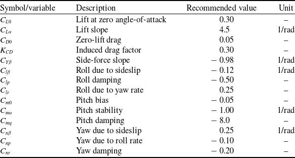


 Z
 Zref

 X
 Xref


 θ

 q


 −mg

 Ftire,f
 Ftire,w1
 Ftire,w2

 Fsusp,f
 Fsusp,w1
 Fsusp,w2


 X˙
 Z˙
 Vair


 θ
 δs,max

 Open access


