INTRODUCTION
Intense relativistic electron beams (IREB) are employed in high power microwave (HPM) sources, which are having several applications in plasma heating, particle acceleration, high-power radar, and many other industrial and military fields (Benford, Reference Benford2008; Benford et al., Reference Benford, Swegle and Schamiloglu2007). The reflex triode virtual cathode oscillator (RT vircator) is one among several types of pulsed HPM sources in use today. The RT vircator is considered to be very attractive due to its high-power capability, frequency tunability, and device simplicity while facing difficult problems in microwave efficiency and frequency stability (Benford et al., Reference Benford, Swegle and Schamiloglu2007; Sullivan et al., Reference Sullivan, Walsh, Coutsias, Granastein and Alexeff1987; Thode, Reference Thode, Granastein and Alexeff1987). Recent research efforts on virtual cathode oscillators have been concentrated on efficiency improvement and oscillation frequency control (Jiang et al., Reference Jiang, Woolverton, Dickens and Kristiansen1999; Jiang & Kristiansen, Reference Jiang and Kristiansen2001; Biswas, Reference Biswas2009; Biswas & Kumar, Reference Biswas and Kumar2007; Menon et al., Reference Menon, Roy, Singh, Mitra, Sharma, Kumar, Sharma, Nagesh, Mittal and Chakravarthy2010). Being a space-charge device IREBs are an integral part of any RT vircator device. However, the effect of IREBs on HPM generation is far from complete understanding.
A RT vircator operates by first emitting an electron beam from a cathode and accelerating it through a semitransparent anode. A space charge (virtual cathode) then forms behind the anode when the space charge limited current of the drift tube is exceeded. During operation, the virtual cathode reflects part of the electron beam, resulting in two possible sources of microwave radiation. The first is from electrons oscillating between the real cathode and virtual cathode and the second is from the oscillating electron cloud or virtual cathode. Another type of space-charge device, the RT, is configured somewhat similarly to the vircator, except that the anode, rather than the cathode, is attached to the center conductor of the transmission line feeding power to the source. HPM radiation is observed when a positive pulse is applied to an anode of a RT (Mahaffey et al., Reference Mahaffey, Sprangle, Golden and Kapetanakos1977). Traditionally, the radiated microwave frequency in a RT vircator is considered to be determined primarily by the virtual cathode oscillation frequency and the electron reflection frequency. However, cavity resonance effect ultimately decides the emitted frequency of radiation (Benford et al., Reference Benford, Price, Sze and Bromley1987), resonant frequencies are enhanced whereas, non-resonant frequencies are suppressed.
The electron beam is generated in the RT vircator device from explosive emission plasma on the cathode surface, which is formed when the strong electric field is applied to the anode-cathode (AK) gap. The cathode plasma expansion across the diode gap changes the effective AK gap during the accelerating pulse and affects the microwave frequency (Price & Benford, Reference Price and Benford1998). It was found that, when the plasma formation at the cathode is completed, and until the pulse ends, the plasma speed is constant and equal to 2 ± 0.5 cm/μs for graphite cathode (Pushkarev & Sazonov, Reference Pushkarev and Sazonov2009). The increase of explosive emission plasma speed can be caused by several factors, such as the ion acceleration in the electric field between the virtual cathode and cathode plasma (Mesyats, Reference Mesyats2004), hydrodynamic expansion of plasma cloud in vacuum, and increase of cathode plasma temperature at its Joule heat by the electron current of the generated beam. Plasma expansion velocity as high as 11 cm/μs has been measured at a very high current density (Roy et al., Reference Roy, Menon, Mitra, Kumar, Sharma, Nagesh, Mittal and Chakravarthy2009). In higher power diodes, the higher plasma-pressure gradient may result in a fast plasma expansion. Expansion velocities of 5 cm/μs correspond to the ion thermal velocity of 25 eV protons (Maron et al., Reference Maron, Sarid, Zahavi, Perelmutter and Sarfaty1989).
Recently, RT has received much attention due its compactness and high peak power capability (Liu et al., Reference Liu, Li, Zhang, Wen, Wan and Zhang2007; Li et al., Reference Li, Men, Liu and Wen2007; Reference Li, Liu, Cheng, Xu, Wan, Chang and Wen2009; Appelgren et al., Reference Appelgren, Akyuz, Elfsberg, Hurtig, Larsson, Nyholm and Möller2006; Chen et al., Reference Chen, Mankowski, Walter, Kristiansen and Gale2007). It was found that the carbon fiber (CF) cathode could improve the quality of the electron beam and dramatically enhance the beam-wave energy conversion efficiency as compared with the conventional stainless steel (SS) cathode in the RT vircator. The peak power of the RT vircator is increased from 200–300 MW in the SS cathode case to over 500 MW in the CF cathode case, and correspondingly, the beam-wave energy conversion efficiency was increased from 4%–5% to over 10% (Liu et al., Reference Liu, Li, Zhang, Wen, Wan and Zhang2007). Experimental results clearly show that the electrons emitted not only from the top of the CF but also from the side surface. Particularly, the plasma is more uniform for CF cathode due to the side surface flashover of the CFs, and plasma expansion velocity is slower than that for conventional metal cathode, which significantly improves the electron beam quality of the CF cathode (Liu et al., Reference Liu, Li, Zhang, Wen, Wan and Zhang2007). Experimental results show that the oscillation mode of a RT vircator had different behaviors between the SS and CF cathodes. Indeed, the microwave frequency using the CF cathode remained almost unchanged throughout the microwave pulse, while a mode hopping occurred in the case of the SS cathode (Li et al., Reference Li, Liu, Wan, Zhang, Wen and Liu2009).
Intense electron beam generation studies were carried out in a planar diode configuration to investigate the effect of the cathode materials on the cathode plasma expansion (Roy et al., Reference Roy, Patel, Menon, Sharma, Chakravarthy and Patil2011). The investigations have been performed for cathodes made of graphite, stainless steel, polymer velvet, carbon coated, and CF (needle type) at the electron accelerator LIA-200 (200 kV, 100 ns, and 4 kA). The diode voltage has been varied from 28–225 kV, whereas the current density has been varied from 86–928 A/cm2 with 100 ns pulse duration. The experimentally obtained electron beam diode perveance has been compared with the one-dimensional (1D) Child-Langmuir law. It was found that initially only a part of the cathode take part in the emission process. The plasma expands at 1.7–5.2 cm/µs for 4 mm anode-cathode gap for various cathode materials. It was found that the plasma expansion velocity increases with the decrease in the cathode diameter. At the beginning of the accelerating pulse, the entire cathode area participates in the electron emission process only for the multiple needle type CF cathodes (Roy et al., Reference Roy, Sharma, Mitra, Menon, Sharma, Nagesh and Chakravarthy2011).
The time-dependent behavior of the oscillation frequency of a RT vircator has been studied for various AK gaps (Roy et al., Reference Roy, Patel, Menon, Sharma, Chakravarthy and Patil2011). The typical electron-beam parameters were 200 kV, 4 kA, and 300 ns, with a current density of a few hundreds of amperes per square centimeter. Time-dependent frequency analysis is applied to the output signal of the RT vircator to investigate the time evolution of the emitted frequency spectrum for various AK gaps. The highest microwave power is emitted when all the power is delivered into a single frequency with minimal mode hopping (Roy et al., Reference Roy, Sharma, Mitra, Menon, Sharma, Nagesh and Chakravarthy2011).
In this paper, we present experimental results for various types of explosive field emission cathodes at three different AK gaps and its effect on RT vircator performance. Experiments were performed using the 1 kJ Marx generator to drive RT vircator to generate HPMs. The 1 kJ Marx generator, is capable of producing a maximum output voltage of 300 kV into a matched load of 25 Ohms with pulse duration of 300 ns full width at half maximum (FWHM) (Sharma et al., Reference Sharma, Kumar, Mitra, Sharma, Patel, Roy, Menon, Nagesh and Chakravarthy2011).
SPACE CHARGE LIMITED ELECTRON FLOW IN THE PLANAR ELECTRON BEAM DIODE
The diode current density j at time t during the pulse, and the total current I are given by the 1D Child-Langmuir law. For a plane parallel diode consisting of a cathode of radius r and a AK gap d the j and I are given by (Miller, Reference Miller1982),
 $$\,j\left(t \right)=\displaystyle{{4 \in _o } \over 9}\left({\displaystyle{{2e} \over {m_e }}} \right)^{1/2} \displaystyle{{V\lpar t\rpar ^{3/2} } \over {\left({d - vt} \right)^2 }}=2.33 \times 10^{ - 6} \displaystyle{{V\lpar t\rpar ^{3/2} } \over {\left({d - vt} \right)^2 }}\comma \;$$
and
 $$I\left(t \right)=j\left(t \right)\, {\rm \pi} \, r^2=2.33 \times 10^{ - 6} \displaystyle{{{\rm \pi} \, r^2 V\lpar t\rpar ^{3/2} } \over {\left({d - vt} \right)^2 }}\comma \;$$
where V is the applied voltage, t is the time during pulse at which j and I are measured; e and m e are electron charge and mass, and ∈o is the free space permittivity and v is the cathode plasma expansion velocity.
The diode impedance Z d is given by,
 $$Z_d \left(t \right)=\displaystyle{{V\lpar t\rpar } \over {I\left(t \right)}}=\displaystyle{{136} \over {V\lpar t\rpar ^{1/2} }}\displaystyle{{\left({d - vt} \right)^2 } \over {r^2 }}\comma \; \quad \lpar V\, in\, MV\rpar .$$
The perveance expression for the electron flow in the planner region of the diode can be defined by
 $$P_{\,planar}=\displaystyle{{I\left(t \right)} \over {V\lpar t\rpar ^{{3 / 2}} }}=2.33 \times 10^{ - 6} \displaystyle{{{\rm \pi} \, r^2 } \over {\left({d - vt} \right)^2 }}.$$
For shorter pulse duration, <100 ns and at the comparatively low current density about 10 A/cm2 electron flow remains unipolar (Saveliev et al., Reference Saveliev, Sibbett and Parkes2003). However, at the higher current density greater than few hundreds of A/cm2 electron flow becomes bipolar (Shiffler et al., 2001). The anode plasma could be generated by either melting and subsequent evaporation of the anode material or by electron stimulated desorption of the contaminants on the anode surface (Shiffler et al., Reference Shiffler, Cartwright, Lawrence, Ruebush, Lacour, Golby and Zagar2003). The charge neutralizations of the electrons by the ions allows approximately 1.86 times the current to flow as compared to single species Child-Langmuir, with the limiting electron current independent of the ion mass (Miller, Reference Miller1982). In that case, Eq. (4) modifies to
 $$P_{\,planar} \lpar Bipolar\rpar =1.86 \times 2.33 \times 10^{ - 6} \displaystyle{{{\rm \pi} \, r^2 } \over {\left({d - vt} \right)^2 }}.$$
A perveance expression for the cathode surface must also include the effect of electron flow from the cathode circumferential edge. Contribution due to edge can be accounted for by using Langmuir-Compton equation (Parker et al., Reference Parker, Anderson and Duncan1974) for cylindrically symmetric space charge limited electron flow. Edge effects in finite area diodes may significantly increase the value of space charge limited current, relative to the prediction of 1D Child-Langmuir Law (Parker et al., Reference Parker, Anderson and Duncan1974; Umstattd & Luginsland, Reference Umstattd and Luginsland2001).
Edge contribution is particularly important for r/d < 1 and can be neglected for r/d > >1.
 $$P_{edge}=\displaystyle{{14.66 \times 10^{ - 6} } \over 8}\displaystyle{{2{\rm \pi} r} \over {d_{} {\rm \alpha} ^2 }}\comma \; $$
where
 $$\eqalign {{\rm \alpha}& =\ln \lpar {d / {vt}}\rpar - 0.4\left[{\ln \left({{d / {vt}}} \right)} \right]^{\, 2}+0.0917\left[{\ln \left({{d / {vt}}} \right)} \right]^{\, 3}\cr & \quad - 0.0142\left[{\ln \left({{d / {vt}}} \right)} \right]^{\, 4}+..... }.$$
The perveance of the total electron flow from the cathode edge and face is equal to the sum of two components. Thus, the diode perveance in the generalized from can be expressed as
 $$P_{diode}=P_{\,planar}+P_{edge}.$$
In case of bipolar space-charge limited flow, the diode perveance in the generalized can be expressed as
 $$P_{diode}=P_{\,planar} \lpar Bipolar\rpar +P_{edge}.$$
Thus, the cathode emission area, the effective diode separation, and the beam envelope are the only parameters that can affect the diode perveance. These interpretations are strictly valid only in the nonrelativistic limit. But the error associated will be small if the electron kinetic energy is less than 500 keV (Parker et al., Reference Parker, Anderson and Duncan1974).
EXPERIMENTAL SETUP
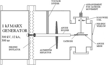
Figure 1 displays schematic the RT vircator along with the 1 kJ Marx generator. The 1 kJ Marx system is a six stage bipolar Marx generator. It consists of 12 MAXWELL make capacitors (0.2 µF, 50 kV) placed linearly. Each capacitor can be charged to ±50 kV and while triggered, all the spark gaps fire together to erect the Marx generator to generate maximum of 300 kV with matched load of 25 Ω. The whole assembly is kept inside a 1.8 meter pressure vessel having a diameter of 750 mm approximately. By varying the pressure of the chamber from 0–3 kg/cm2 output voltage can be varied from 120 kV to 300 kV at the load terminal. To get a good pulse shape and fast rise time a peaking spark gap is used to connect the system with the load. System is capable to operate in burst mode with around 10 Hz repetition rate at matched load (Sharma et al., Reference Sharma, Kumar, Mitra, Sharma, Patel, Roy, Menon, Nagesh and Chakravarthy2011).
Schematic of the experimental setup.

The RT vircator is housed inside an 8-in six-way SS vacuum chamber (length 40 cm, diameter 40 cm) with one of the ports bolted to the vacuum system. A SS vacuum chamber (length 50 cm, diameter 63.5 cm also connected to the RT in order to house a 35.0 cm diameter aluminum reflector into the anode holder. In the present experiment, the reflector is placed at a distance of 35 cm from the cathode centre.
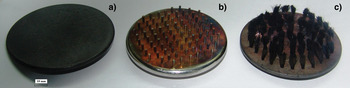
The high voltage pulse generated from the pulse power system is applied to the anode. The diode consists of a planar cathode and copper anode mesh (150 mm diameter) at various AK gaps and various voltage levels. The AK gap separation can be adjusted by screwing the cathode brass stock inward or outward. Three different types of cathodes have been used in the experiment, a SS nail cathode, CF cathode (needle type) (Roy et al., Reference Roy, Patel, Menon, Sharma, Chakravarthy and Patil2011) and a plane graphite cathode (Roy et al., Reference Roy, Patel, Menon, Sharma, Chakravarthy and Patil2011). A multiple-needle cathode of 57 mm diameter was prepared based on CF emitters. The multiple needle CF cathode was constructed by mounting the separate CF tufts, 2 mm in diameter and 9 mm long, in a graphite substrate with a lot of holes spaced by 5 mm. Each tuft was composed of thousands of CFs. The multiple needles SS nail cathode was made of 56 mm diameter, each nail has a blunt emitting surface with a 1.5 mm diameter and 5 mm length. The outer edge of the graphite cathode was rounded with 10 mm radius. Figure 2 displays a photograph of all the cathodes. Prior to use, the graphite cathode surface was roughened by sanding it with an emri paper. The anode was made of copper wire with a diameter of 0.5 mm and a 2-mm square mesh. A resistive CuSO4 voltage divider and a self-integrating Rogowski coil were used to measure the diode voltage and current pulses respectively. The voltage divider is placed parallel to the cathode plane touching the anode holder. An open ended wave-guide was used to radiate HPM into the atmosphere. A vacuum level on the order of <1 × 10⁻⁵ mbar was maintained in the RT vircator chamber by a diffusion pump backed by a rotary pump. The typical electron beam parameters were 200 kV, 9 kA, and 300 ns.
Photograph of the (a) Graphite cathode, (b) SS nail cathode, and (c) Multiple needle CF cathode.

The HPM signal was captured by a B-dot probe placed one meter from the RT vircator window at the boresight. A shielded room was situated approximately 20 meters away from the RT system. All the oscilloscope measurements were carried out inside the shielded room. For each shot, the beam parameters were recorded using a 500 MHz, 2GS/s oscilloscope. Various components used in the diagnostics were calibrated using a standard modulated (few ms to ns) RF source. The microwave sensor consisting of a B-dot probe has been used to catch the microwave signal in a wide frequency range (<6 GHz) and send it to a high-speed digital storage oscilloscope (with a sampling rate of 40 GS/s) through a coaxial RF cable. The B-dot probe is a pair of magnetic sensors that measure the rate of the field change. Fourier transforms and the Time Frequency Analysis has been carried out with the digitally stored data using standard software. Since the magnetic field strength was only measured on the boresight, the radiation pattern was not known, and therefore, the total radiated HPM power and energy cannot be estimated.
EXPERIMENTAL RESULTS AND ANALYSIS
Graphite Cathode
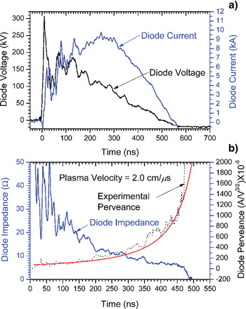
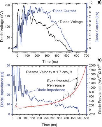
The diode voltage and current waveforms for 77 mm diameter graphite cathode and 12 mm AK gap is shown in Figure 3a. Electron beam diode time varying impedance and perveance values were calculated using the voltage and current waveforms. The starting point or the zero time for perveance calculations was taken when the current pulse started rising. The experimental impedance and perveance derived from the diode voltage and current is shown in Figure 3b. The cathode plasma expands toward the anode, increasing the diode perveance.
(a) Voltage and current waveform with a 77 mm diameter graphite cathode at 12 mm accelerating gap. (b) The temporal behavior of the diode impedance and perveance. The continuous line represents the calculated perveance from Eq. (4) assuming v = 2.0 cm/µs. (Corresponding to the shot Sl. No. 4 in Table 1.)

Cathode plasma expansion velocity and the initial cathode emission area have been calculated from the perveance data. In Figure 3b, result of this calculation is shown where the plasma expansion velocity is the fitting parameter. The best fit for the theoretical perveance Eq. (4) was obtained assuming the plasma expansion velocity to be 2.0 cm/µs. The peak current density in this case was j = 204 A/cm2. One can see that the plasma expansion velocity measured in this experiment for a graphite cathode is in close agreement with the value reported earlier (Pushkarev & Sazonov, Reference Pushkarev and Sazonov2009; 2011). One can see from Figure 3b that the experimental perveance deviates from the theoretical one after about 200 ns from the beginning of the high voltage pulse probably due to the commencement of the bipolar space-charge limited flow (Li et al., Reference Li, Liu, Cheng, Xu, Wan, Chang and Wen2009).
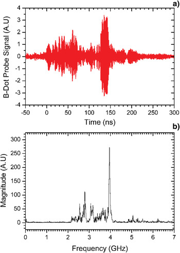
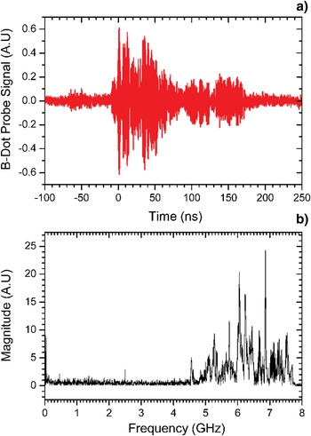
The Figure 4a displays the corresponding HPM signal captured by the B-dot probe. The FFT of the B-dot probe signal is shown in Figure 4b. One can see from Figure 4a that the HPM pulse is about 230 ns in duration although the electron beam pulse length is about 500 ns. The virtual cathode oscillates at a 4 GHz dominant frequency and has several secondary peaks below 4 GHz frequency.
(a) B-dot probe signal for the graphite cathode. (b) FFT of the B-dot probe signal.

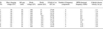
If the Fourier transform is carried out within a relatively short time window, by shifting the time window within the pulse length of the output microwave, one can obtain the time variation of the microwave spectrum (Hegeler et al., Reference Hegeler, Partridge, Schamiloglu and Abdallah2000; Cohen, Reference Cohen1995). The digitally stored B-dot probe data is subjected to a time-frequency analysis. The spectrogram is derived from the Fourier transform of a windowed portion (rectangular window) of the signal being analyzed. The spectrogram has been a useful tool, but it suffers from a time-frequency uncertainty effect because of the analysis window (Cohen, Reference Cohen1995). A time frequency analysis of the B-dot probe signal reveals that initially the dominant frequency emitted is of 2.8 GHz, however after about 200 ns from the beginning of the HPM pulse, the dominant frequency shifted to 4 GHz and remains constant thereafter. Table 1 summarizes the experimental results carried out with a graphite cathode for three different AK gaps. One can see from Table 1 that for almost all of the AK gaps the cathode plasma expansion velocity is about 2.0 cm/µs. The emitted dominant HPM frequency is a strong function of diode current density and decreases as the current density reduces. For all of the AK gaps and various charging voltages more than one frequency is emitted. The highest radiated electric field strength is 47.6 kV/m, measured for 12 mm AK gap and 30 kV Marx generator charging voltage at 1 m distance from the RT vircator window.
Summary of the experimental results carried out with a 77 mm diameter graphite cathode for three different AK gaps

SS Nail Cathode
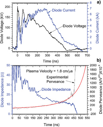
Figure 5a displays the diode voltage and current waveforms for 56 mm diameter SS nail cathode at 12 mm AK gap. The experimental impedance and perveance derived from the diode voltage and current is shown in Figure 5b. The best fit for the theoretical perveance was obtained when the bipolar space-charge limited flow was taken into account (Eq. (5)]. The estimated cathode plasma expansion velocity was 1.8 cm/µs. The peak current density in this case was j = 285 A/cm2. An excellent agreement between the theoretical and experimental perveance was observed until about 450 ns, after that perveance increases very rapidly. One can see from Figure 2b that after nine shots surface of the SS nail cathode has become red due to deposition of sputtered copper anode material on cathode.
(a) Voltage and current waveform with a 56 mm diameter SS Nail cathode at 12 mm accelerating gap. (b) The temporal behavior of the diode impedance and perveance. The continuous line represents the calculated perveance from Eq. (5) assuming v = 1.8 cm/µs. (Corresponding to the shot Sl. No. 4 in Table 2.)

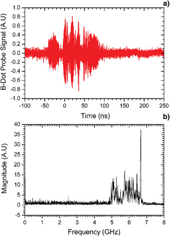
The Figure 6a displays the corresponding HPM signal captured by the B-dot probe. The FFT of the B-dot probe signal is shown in Figure 6b. The dominant frequency occurs at 6.6 GHz. The HPM pulse duration is about 150 ns. A time frequency analysis shows that initially 5.0 GHz frequency was excited and after about 50 ns the 6.6 GHz dominant frequency arises and remains for the rest of the signal.
(a) B-dot probe signal for the SS nail cathode. (b) FFT of the B-dot probe signal.

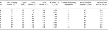
Table 2 summarizes the experimental results carried out with a SS nail cathode for three different AK gaps. One can see from Table 2 that the estimated plasma expansion velocity using the perveance expression from Eq. (4) is 2.8 cm/µs. As compared to the graphite cathode the measured radiated electric field strength for the SS nail cathode at 1 m distance from the RT vircator window was substantially less and a maximum electric field of 18.6 kV/m has been measured for 27 kV Marx generator charging voltage at 10 mm AK gap. For the SS nail cathode, the cathode plasma expands at a velocity of 1.8–2.8 cm/µs. The present measurement of cathode plasma expansion velocity is in close agreement with the 2.2 cm/µs reported earlier (Liu et al., Reference Liu, Li, Zhang, Wen, Wan and Zhang2007) at a current density j = 338 A/cm2.
Summary of the experimental results carried out with a 56 mm diameter SS nail cathode for three different AK gaps

CF Cathode
It was shown that the CF cathode could improve the quality of the electron beam and dramatically enhance the beam-wave energy conversion efficiency as compared with the conventional SS cathode in the RT vircator (Liu et al., Reference Liu, Li, Zhang, Wen, Wan and Zhang2007). The plasma forming on the CF cathode is more uniform as a result of the surface flashover discharge along the whole surface of the CF. The diode voltage and current waveforms for 57 mm diameter CF cathode and 12 mm AK gap is shown in Figure 7a. The experimental impedance and perveance derived from the diode voltage and current is shown in Figure 7b. The best fit for the theoretical perveance was obtained when both the bipolar space-charge limited flow and edge emission were taken into account (Eq. (8)). The estimated cathode plasma expansion velocity was 1.7 cm/µs. The peak current density in this case was j = 353 A/cm2.
(a) Voltage and current waveform with a 57 mm diameter CF cathode at 12 mm accelerating gap. (b) The temporal behavior of the diode impedance and perveance. The continuous line represents the calculated perveance from Eq. (8) assuming v = 1.7 cm/µs. (Corresponding to the shot Sl. No. 3 in Table 3.)

Figure 8a displays the corresponding HPM signal captured by the B-dot probe. The FFT of the B-dot probe signal is shown in Figure 8b. The dominant frequency occurs at 6.8 GHz. The HPM pulse duration is about 200 ns. A time frequency analysis shows that initially 6.0 GHz frequency was excited and during the end of the HPM pulse the 6.8 GHz dominant frequency arises and remains for the rest of the signal.
(a) B-dot probe signal for the CF cathode. (b) FFT of the B-dot probe signal.

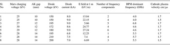
Table 3 summarizes the experimental results carried out with a CF cathode for three different AK gaps. One can see that the estimated cathode plasma expansion velocity for CF cathode is 1.5–1.7 cm/µs, lowest among all three cathodes. The measured cathode plasma velocity is slightly higher than the value 0.9–1.0 cm/μs reported earlier (Liu et al., Reference Liu, Li, Zhang, Wen, Wan and Zhang2007) at a current density j = 286 A/cm2. However, the radiated peak field measured at 1 m distance from the RT vircator window is lower than the graphite cathode but higher than SS nail cathode. The maximum radiated peak electric field is 27.2 kV/m at 12 mm AK gap and 29 kV Marx generator charging voltage.
Summary of the experimental results carried out with a 57 mm diameter CF cathode for three different AK gaps

DISCUSSIONS
It was shown experimentally that the plasma forming on the CF cathode is more uniform as a result of the surface flashover discharge along the whole surface of the CF (Lui et al., 2007). But, the electron emission of the metal cathode is confined to the tips of the emitters on the cathode, which obviously differs from the electron emission mechanism of the CF cathode (Lui et al., 2007). In addition, the slower plasma expansion velocity has been measured with the cathode made with CFs, and the electron beam extracted from the CF cathode has a higher quality than the case of the SS cathode (Lui et al., 2007). Our experimental results also verify the earlier results of slower plasma expansion velocity with the CF cathode, as well as higher radiated HPM field measured with the CF cathodes as compared to the SS nail cathodes.
RT vircator experiments have been reported at a peak diode voltage of 450 kV and with a current density j = 280–440 A/cm2 using both CF and SS nail cathodes (Li et al., Reference Li, Liu, Wan, Zhang, Wen and Liu2009). The microwave frequency using the CF cathode remained almost unchanged throughout the microwave pulse, while a mode hopping occurred in the case of the SS cathode (Li et al., Reference Li, Liu, Cheng, Xu, Wan, Chang and Wen2009). The changes in the emitting area of CF cathode showed a self-quenching process, which is not observed in the case of SS nail cathode (Li et al., Reference Li, Liu, Wan, Zhang, Wen and Liu2009). By examining the cross-section of electron beam, the electron beam for CF cathode was significantly centralized, while the discrete beam spots appeared for SS cathode (Li et al., Reference Li, Liu, Cheng, Xu, Wan, Chang and Wen2009). In the case of SS cathode, two modes (2.45 and 2.66 GHz) are excited, and these radiations are emitted at different times. Indeed, an 80 ns pulse occurred at 2.45 GHz, which is followed by a higher power pulse at 2.66 GHz during 100 ns. In the case of the CF cathode, interestingly, the dominant frequency was around 2.68 GHz throughout the pulse, with the lack of mode hopping (Li et al., Reference Li, Liu, Wan, Zhang, Wen and Liu2009). It was shown that the beam current for CF cathode is higher than the Child-Langmuir space-charge limited current but less than the bipolar space-charge limited until τ d = 350 ns, after that the beam current becomes bipolar (Li et al., Reference Li, Liu, Cheng, Xu, Wan, Chang and Wen2009).
In the present experiment with RT vircator using graphite, CF, and SS nail cathodes at a peak diode voltage 150–200 kV, peak diode current 5–11 kA with AK gap ranging from 10–14 mm shows mode hopping due to sudden change in the diode current and the RT vircator oscillation frequency increases at τ d ≈ 200 ns. The RT vircator peak power may reduce due to the mode hopping (Roy et al., Reference Roy, Patel, Menon, Sharma, Chakravarthy and Patil2011). For the graphite cathode, always more than one radiated frequency has been observed and the dominant frequency remains in the range of 1.55–4.2 GHz. On average the HPM pulse exists for 200 ns for the graphite cathode.
The virtual cathode oscillation frequency is given by
 $$f_{vc} = 10.0 \left({J \over \beta \gamma} \right)^{1/2} ({\rm GHz}),$$
where J is the current density in kA/cm2 and β = v/c, c = velocity of light. It was found that for the RT vircator, the dominant frequency measured by the B-dot probe qualitatively agrees with the Eq. (9) for all of the cathodes.
With the SS nail cathode for the first two shots at 10 mm AK gap the cathode plasma expansion velocity was very high (2.8 cm/µs) compared to the other shots. Interestingly, it was observed that for these first two shots, the RT vircator emits a single frequency. For all other shots at three different AK gaps, the RT vircator emits several frequencies. Also the mode hopping has been observed for several shots. The diode voltage pulse duration (FWHM) for the first two shots is about 170 ns and about 200 ns, respectively. Very fast cathode plasma expansion velocity resulted in a shorter pulse voltage duration compared to the other shots. The shorter pulse duration may result in a single emitted frequency for the RT vircator. In general, except for the first two shots, the emitted frequency is much higher (5.4–6.6 GHz) than the graphite cathode. The average microwave pulse duration obtained for the SS nail cathode is 140 ns.
For the CF cathode, the emitted frequency was in the range of 4–6.8 GHz. In general, for CF cathode, the RT vircator emits several frequencies and also the mode hopping has been observed for few shots. On average the CF cathode emits HPM for 142 ns duration. Therefore, the HPM pulse duration for CF cathode is slightly higher than the SS nail cathode, however much smaller than the graphite cathode. Previous experiments on RT vircator also reported smaller HPM pulse duration for SS nail cathode compared to the CF cathode (Liu et al., Reference Liu, Li, Zhang, Wen, Wan and Zhang2007). However, in another RT vircator experiment, the comparison was made at an AK gap of 10 mm, and it was found that the duration of the microwave pulse was, on average, 10% longer using SS nails instead of carbon velvet (Appelgren et al., Reference Appelgren, Akyuz, Elfsberg, Hurtig, Larsson, Nyholm and Möller2006). The maximum radiated power varied slightly, about 5%, in favor of the carbon velvet cathode, and the mean power was, on average, 15% higher using the carbon velvet emitter (Appelgren et al., Reference Appelgren, Akyuz, Elfsberg, Hurtig, Larsson, Nyholm and Möller2006). Another RT vircator experiment six different cathodes were tested (Chen et al., Reference Chen, Mankowski, Walter, Kristiansen and Gale2007). It was shown that the metal and CF cathodes have uniform current emission in both time and space (Chen et al., 2007/). However, the SS nail cathode exhibited shortest microwave pulse duration, in agreement with our results.
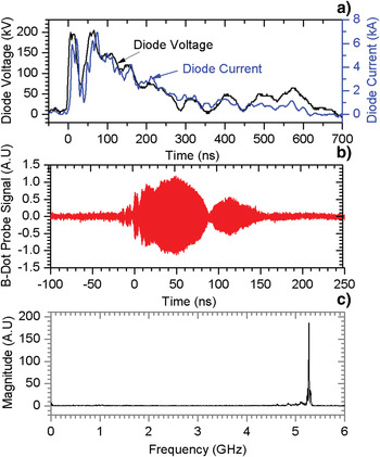
It was found that the cathode plasma expansion velocity for the CF cathode is lowest among all three cathodes; however, the pulse duration for the CF cathode is not the largest. Therefore, the HPM pulse duration is not dominated by the shorting of the diode gap due to cathode plasma expansion (Price & Benford, Reference Price and Benford1998). Figure 9a displays the diode voltage and current waveform using CF cathode at14 mm AK gap. Figures 9b and 9c displays the corresponding B-dot probe signal and its FFT. One can see that the diode voltage pulse duration (FWHM) is about 170 ns and the virtual cathode oscillates at a single frequency of 5.3 GHz. Therefore, the shorter voltage pulse duration has resulted in a single emitted frequency of the RT vircator.
(a) Diode voltage current waveform, (b) Corresponding B-dot probe signal, (c) FFT of the B-dot probe signal for the CF cathode at 14 mm AK gap showing a single emitted frequency. (Corresponding to the shot Sl. No. 6 in Table 3.)

The aluminum reflector position with respect to the cathode center has significant influence on the RT vircator power and frequency. The present experiment has been conducted at a fixed reflector position 350 mm from the cathode centre. In the future, the RT vircator performance will be studied varying the position of the aluminum reflector with respect to the cathode center.
CONCLUSIONS
Intense electron beam and HPM generation studies were carried out in a RT vircator to investigate the effect of the cathode materials on radiated HPM field and frequency. The investigations have been performed for three different explosive field emission cathode materials. The diode voltage has been varied from 150–210 kV and the current density has been varied from 200–400 A/cm2 with 300 ns pulse duration. The electrode plasma expansion velocity has been estimated from the perveance data. It was found that the CF cathode has the lower cathode plasma expansion velocity of 1.7 cm/μs. The cathode plasma expansion velocity for the SS nail cathode is in the range of 1.8–2.8 cm/μs, whereas the same for the graphite cathode is in the range of 1.9–2.5 cm/μs. The graphite cathode exhibited maximum radiated HPM field and pulse duration. The emitted frequency from the RT vircator ranges in between 1.5–6.8 GHz. Although the diode voltage pulse duration (FWHM) is about 300 ns the microwave pulse duration never exceeds 200 ns. Highest microwave pulse duration has been achieved for the graphite cathode and the lowest for the SS nail cathode. The RT vircator emits a single frequency for SS nail and CF cathode when subject to a shorter voltage pulse duration. The highest radiated electric field strength is 47.6 kV/m, measured for graphite cathode at 12 mm AK gap and 30 kV Marx generator charging voltage at 1 m distance from the RT vircator window.
ACKNOWLEDGMNETS
We are very much thankful to Dr. L. M. Gantayet, Director, BTD Group, BARC, and Dr. A. K Ray, Raja Ramanna Fellow, BARC for providing useful guidance, facilities and efficient manpower. We would like to place on record our sincere thanks to Mr. S. R. Raul, Mr. Sachin Patil, Mr. S. Vaity, and Mr. N. K. Lawangare and for technical help.