


1. Introduction
Avalanches, debris and mud flows as well as landslides are common natural phenomena to the inhabitants of high-mountain areas who have learned to accept their occasional occurrence and to avoid the damage that accompanies them. Nevertheless, accidents causing damage to property and loss of life have regularly occurred in the past and continue to occur today. This is why the study of avalanches is a topic of permanent public concern in mountainous regions. The physics of the release or failure of a large mass of soil, gravel or snow and the dynamics of its motion must be understood if the concomitant danger is to be avoided or the impact of a moving mass on the avalanche track or on obstructing buildings is to be estimated. One hopes that understanding their physical basis will enable the appropriate defensive measures to be taken. An exact analysis of an avalanche is perhaps an unattainable goal. Nevertheless, the last few years have witnessed increased efforts devoted to the physical understanding of avalanche formation and motion in complex topography.
In this paper, we present an extension of the Reference Savage and HutterSavage and Hutter (1989) (SH) model by Reference Pudasaini and HutterPudasaini and Hutter (2003) to rapid shear flows of dry granular masses in a non-uniformly curved and twisted channel and some basic numerical results on it. The computations presented here are for a particular case of the extended theory, namely for the basal topography which is curved downhill and laterally channelized. To describe the shock phenomenon observed in granular avalanches when supercritical flow merges into a region of subcritical flow and to ensure the numerical stability, a shock-capturing numerical scheme is used to solve the model equations. The intention is to obtain some basic insights into these new model equations. The results highlight fundamental characteristics of the dynamics of flowing avalanches.
2. Overview of the SH Model
Reference Savage and HutterSavage and Hutter (1989) developed a continuum hydraulic theory to describe the evolving geometry of a finite mass of a granular material and the associated velocity distribution as an avalanche slides down an inclined surface. In order to formulate a realistic model, the following assumptions were made:
(i) The moving dry and cohesionless granular mass is incompressible and obeys a Mohr–Coulomb yield criterion both inside the deforming mass and at the sliding basal surface.
(ii) The geometries of the avalanching masses are shallow in the sense that typical avalanche thicknesses are small in comparison to the extent parallel to the sliding surface.
(iii) To obtain a dimensionally reduced theory the field equations are integrated through the depth of the avalanche.
(iv) Scaling analysis isolates the physically significant terms in the equations and identifies the terms that can be neglected.
The simple spatially one-dimensional model of SH, applicable along a straight sliding surface, has been generalized to higher dimensions, to more complex geometries, and has also been tested against realistic laboratory experiments. Very good agreement was obtained between the theoretical predictions and the experiments (see Reference Savage and HutterSavage and Hutter, 1991; Reference Gray, Wieland and HutterGray and others, 1999; Reference Denlinger and IversonDenlinger and Iverson, 2001; Reference Pudasaini and HutterPudasaini and others, 2003). Here we will focus on a three-dimensional extension of the SH model as well as its application to avalanche motion over a realistic flow path.
3. Effect of the Topography
Curved flow-path surfaces strongly influence the flow dynamics because transverse shearing and cross-stream momentum transport occur when the topography obstructs or redirects the motion due to its curvature and torsion. Local deceleration and deposition of mass may occur due to energy dissipation. Resistance due to basal friction is modified by “centrifugal forces” induced by the bed curvature as well as torsion.
Recently Reference Pudasaini and HutterPudasaini and Hutter (2003) extended the SH theory to flows of dry granular masses in a non-uniformly curved and twisted channel. In the extended theory a general orthogonal coordinate system is introduced that is able to describe a finite region of a natural landscape. Consider an avalanche-prone landscape and a subregion of it where the topography allows identification of the avalanche track. A single space curve parallel to the talweg of the valley is singled out as a master curve C (which can be obtained by shifting the talweg along its normal or vertical direction) from which the track topography will be modelled. The curvature and torsion of the master curve,  are assumed to be known as functions of the arc length x of the master curve. Then, an orthogonal coordinate system along the master curve is introduced and the model equations are derived in this general coordinate system. In the model equations under consideration in this paper, (x; y) form a curved reference surface, where x is the coordinate along the talweg of a mountain valley, while y is the circular arc length in a cross-sectional plane perpendicular to the talweg whose value is determined by the relation y = εθzT, where ε is the aspect ratio between the avalanche height and the extent (both the length and width are assumed to be of the same order of magnitude), θ is the azimuthal angle which accounts for the cross-slope curvature and zT (usually zT ≫ 1) is the radial distance between the master curve ~and the talweg and z is the coordinate perpendicular to the reference topography. Every quantity in this paper is written in non-dimensional form. The channel topography and the geometry of the avalanche in lateral and longitudinal directions are illustrated in Figures 1 and 2, respectively.
First, we discuss some terms and parameters arising in the model equations presented in the next section. gx, gy and gz are the projected components of the gravitational acceleration along the downslope, cross-slope and normal directions, respectively, and are given by
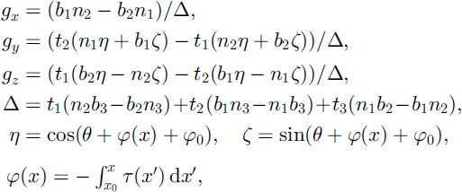
where φ0 is an arbitrary constant and φ(x) accounts for the accumulation of the torsion. (ti); (ni) and (bi); 1 ≤ i ≤ 3, are the components of T, Nand B, respectively, with respect to the standard Cartesian basis (see Fig. 1). The aspect ratio ε, and λ, the measure of curvature relative to the typical avalanche length, are both small numbers. The basal topography (which includes the small-scale features of the topography) will be denoted by b(x; y).
For a given value of the arc length, the avalanche domain in the lateral direction occupies a region in a circular section of a plane perpendicular to the talweg of the valley, and θ is the azimuthal angle in this plane. OO= zT is the radial distance between the master curve and the talweg. The lateral coordinate, y, is determined by the transformation y = θzT. {T;N;B} is the moving orthonormal unit triad following the talweg (equivalently the master curve). ζ̃ is the slope angle of the talweg with the horizontal. The depth of the avalanche in this section is represented by a height function h(x; y; t) and is measured in the radial direction.

The extended theory is designed to model the flow of the (debris) avalanches over curved and twisted channels having general curvature and torsion. Although there are other models that consider the problem of avalanche motion over curved slopes (e.g. Reference Maeno and NishimuraMaeno and Nishimura, 1987; Reference Norem, Irgens and SchieldropNorem and others, 1987; Reference Savage and NohguchiSavage and Nohguchi, 1988; Reference Zwinger, Kluwick and SamplZwinger and others, 2003), the model equations considered in this paper explicitly and simultaneously include the curvature and torsion effects in a systematic and rigorous manner. This makes the extended model amenable to realistic snow and debris motions down arbitrary guiding topographies. In fact, Geographic Information System (GIS) applied to mountainous avalanche- and debris-prone regions can be applied to this model, which provides the geometrical basis for realistic application and tuned to practical use, and thus lays the theoretical foundation towards this end. In contrast to the original SH theory and all its previous extensions (e.g. Reference Gray, Wieland and HutterGray and others, 1999; Reference Wieland, Gray and HutterWieland and others, 1999; Reference Pudasaini, Eckart and HutterPudasaini and others, 2003a, Reference Pudasaini, Hutter and Eckartb), an arbitrary space curve is used to define an orthogonal curvilinear coordinate system. The final governing balance laws of mass and momentum are written in these coordinates. Reference Pudasaini and HutterPudasaini and Hutter (2003) are thus able to study the simultaneous effects of curvature and torsion on the flow avalanche in channels, which have not been investigated analytically before.
4. Model Equations
As in the previous models of the SH theory, Reference Pudasaini and HutterPudasaini and Hutter (2003) recently formulated the balance laws of mass and momentum as well as the boundary conditions in slope-fitted curvilinear coordinates, averaged these equations over depth and then non-dimensionalized the averaged equations. The final thickness-averaged balance laws of mass and momentum in the downslope and cross-slope directions take the form



where h is the depth of the avalanche measured along the normal direction of the reference surface and the factors x and y are defined, respectively, as

The terms sx and sy represent the net driving accelerations in the downslope and cross-slope directions, respectively, and are given by


The magnitude of the velocity field tangential to the reference (basal) topography.
The first terms on the righthand side of Equations (6) and (7) are due to the gravitational accelerations in the down- and cross-slope directions, respectively. The second terms emerge from the dry Coulomb friction, and the third terms are the projections of the topographic variations along the normal direction.
Kx and Ky in Equation (5) are called the earth pressure coefficients. Elementary geometrical arguments may be used to determine these values as functions of the internal () and basal (δ) angles of friction, (Reference Hutter, Siegel, Savage and NohguchiHutter and others, 1993),

where Kx and Ky are active during dilatational motion (upper sign) and passive during compressional motion (lower sign). These values are selected according to

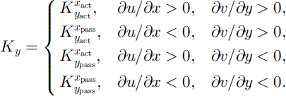
Equations (2–4), which are written in non-dimensional form, constitute a two-dimensional conservative system of equations. These extended model equations can reproduce all previous model equations of the SH theory mentioned at the end of section 2. There are several advantages of the model equations considered in this paper. They are as follows:
(i) They simultaneously include the curvature and torsion of the basal topography. Therefore, the model equations can be utilized to describe the flow of avalanches along non-uniformly curved and twisted channels.
(ii) There is a non-zero gravity term gy in the cross-slope direction. The torsion effect η of the topography is included in the net driving-force components sx and sy in the two flow directions. The y coordinate is curved in the cross-slope direction, including the cross-slope curvature, which was just a straight line before. For a torsion-free master curve, which lies in a vertical plane, these model equations exactly reproduce all previous extensions of the Savage–Hutter equations. Also note that in applications and numerical computations it is convenient to take the sign of gz to be negative, which corresponds to the upward-pointing normal of the talweg. With this convention, these model equations can exactly reproduce the previous equations of Reference Gray, Wieland and HutterGray and others (1999) as a special case. In this sense, there is an enormous application of these equations.
(iii) We can form a three-dimensionally curved and twisted channel using downslope and cross-slope coordinates x and y and we do not necessarily need to superimpose basal topography on top of the reference topography. In principle, it is thus possible to model a given channel or avalanche gully by choosing θ appropriately as a function of the downslope coordinate. These are considerably new contributions in the model equations which we think are crucial to describe the motion of avalanches in curved and twisted channels.
Given the master curve, C, the material parameters δ and and the elevation of the basal topography, b, above the curved reference surface, Equations (2)–(4) allow h; u and υ to be computed as functions of space and time once appropriate initial and boundary conditions are prescribed, where h is the avalanche depth and (u; υ) are the depth-averaged velocity components parallel to the flow surface.
5. Applications to Flows in Cylindrical Channels
Due to the hyperbolicity and non-linearity of the model equations, numerical finite-difference solutions with the traditional high-order accuracy are often accompanied with numerical oscillations of the depth profile and velocity field. This usually leads to numerical instabilities unless these are properly counteracted by a sufficient amount of artificial numerical diffusion. Here, a non-oscillatory central (NOC) difference scheme with total variation diminishing (TVD) limiter for the cell reconstruction is employed which gives high-resolution solutions without spurious oscillations (for more detail, see, e.g., Reference LeVequeLeVeque, 1992; Reference TaiTai, 2000).
In order to test the model equations of section 4, we consider an idealized mountain subregion in which the non-twisted talweg is defined by the slope function
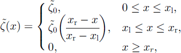
where  is the straight upper part of the talweg which merges into a horizontal run-out plane as shown in Figure 2, and xl = 11.5 and xr = 14.5 are the (non-dimensional) initial and final points of the continuous transition. The azimuthal angle θ (which includes the cross-slope curvature) is confined to the interval [-14.32˚; 14.32˚], and the non-dimensional distance is set to zT = 20, corresponding to
 (see Fig. 1). A hemispherical cap with non-dimensional radius R0 = 1.04 holding the granular material in it is placed at (x0; y0) = (3.0; 0.0) of the chute and suddenly lifted. The granular mass commences to slide and deform continuously along the chute unless the bed friction is larger than the downslope component of gravity. The values of the material parameters are chosen as γ = 33˚ and = 43˚ which correspond to marble chips with mean diameter 2–4mm.
Avalanche passing through the transition into the run-out zone in a vertical plane containing the talweg of the valley. In this picture, xl and xr are the left and right end-points of the continuous transition between the straight inclined upper part with inclination angle ζ̃0 and the horizontal run-out in the valley.
Figure 3 depicts the thickness contours of the avalanching body at ten non-dimensional time-steps. Figure 3a–d clearly show that once the cap is opened, the avalanche accelerates and spreads rapidly in the downslope direction due to the channelling effect in the cross-slope direction. The avalanche decelerates rapidly as soon as it enters the run-out zone, from Figure 3d for t > 4.5. Due to the continued mass flux from the tail, its front is then able to spread out laterally as seen in Figure 3e–g. After t = 7.5 (Fig. 3f), due to the channelling effect of the cross-section, the tail of the avalanche is reducing in width, but the head of the avalanching body is expanding in width in the run-out zone. The curvature of the transition zone induces a shock associated with the height of the avalanche and moving upstream from time t = 9.0 (Fig. 3g) onward. The avalanche comes to rest after t = 13.5. Figure 3a–c indicate that due to the dilatations, the granular body is extending in all directions, mainly in the downhill direction. Although the front is descending rapidly, the tail moves upward in the beginning because of the earth pressure. At t = 4.5 (Fig. 3d) the front reaches the transition zone while the tail also starts to move downward. At t = 6.0 (Fig.3e), the front part of the body has fully reached the transition zone. Therefore the mass at the front is contracting due to the effect of the passive earth pressure coefficient, but the mass in the tail is still extending. At t = 7.5 (Fig. 3f), the deposition of the mass starts in the vicinity of the lower end of the transition zone. Owing to the effect of the curvature, the flowing body starts contracting longitudinally but extending laterally. After t = 9.0 (Fig. 3g), a steep surface (height) gradient starts to develop on the tail side of the avalanche. Although the front of the body is almost at standstill, the mass from the tail is continuously flowing down and is deposited on the tail side of the body. This is the main mechanism for the development of the shock front moving upstream. The physical explanation for this is that from the front there is a strong resistive force from the bed which prevents the body from further sliding. So, mass arriving from the upper part of the channel must be deposited at the back side of the body. Consequently, the stopped body must extend upward. Figure 3h–j show the continuous development of the upward-moving shock. At the same time, there is no motion at the front. Due to the partial lateral confinement, the extension of the body in the cross-slope direction is almost negligible.
A sequence of numerical snapshots of avalanching motion of a granular material with internal and basal friction angles = 43˚ and δ = 33˚, for different time points (a–j). The contours of equal thickness are plotted at ten time intervals using “unrolled” projected non-dimensional curvilinear coordinates (x; y). The transition zone lies between x = 11.5 and x = 14.5. The 45˚ inclined section lies on the left, and the horizontal part lies on the right of each panel. The talweg of the valley is indicated by the line y = 0. The panels thus demonstrate the deformation and settling of avalanches in cylindrically curved (in both down-slope and cross-slope directions) channels.
Figure 4 depicts the channelling effects for different channel curvatures. Parameter values are the same as in Figure 3. The contours represent the final deposits of avalanches for four different channel curvatures. As the value of the parameter θ increases, lateral curvature increases and the width of the channel decreases. The values of θ = 0˚; 15˚; 25˚ and 45˚ correspond to the non-dimensional distances (representing, to some extent, the radius of curvature of the lateral bed profile) 1; 19.1; 11.46 and 6.4, respectively, while the range of y is kept fixed as before, i.e. Consequently, with the increase of θ the granular material tends to accumulate around and along the talweg of the channel, the geometries of the deposited piles are changed, and both the pile heights and the run-out distances increase considerably. This effect is directly associated with the lateral component of the gravitational acceleration (gy) which depends on the lateral curvature (this was always zero in previous extensions of the theory).
Channelling effects; parameter values are as in Figure 3. The contours represent the final deposits (at t = 13.5) of avalanches for four different channel widths (curvatures) corresponding to the parameter θ. As the value of the parameter θ increases, the width of the channel decreases. Consequently, the granular materials tend to accumulate around and along the talweg of the channel, the geometries of the deposited piles are changed, and both the pile heights and the run-out distances increase.
In order to analyze the dispersion of the avalanching mass quantitatively, we consider the total volume  and define the center of the mass as follows:
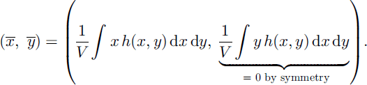
The dispersion of the deformable granular body can then be computed by the following (standard deviation) formula (where “dis” stands for dispersion):
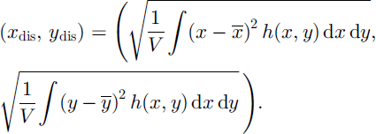
Table 1 represents the data for the dispersion of the sliding and deforming granular body for different non-dimensional time-steps and azimuthal angles. Other parameter values are the same as in Figure 4. Analyzing the table, we arrive at the following conclusions:
(i) Since x(t) is the same for all θ the center-of-mass position is independent of the azimuthal angle θ, at all times. This is exactly what one would expect since the equation of motion for the center of mass will not be affected by lateral spreading. The dispersion in the downhill direction first increases then decreases but the dispersion in the cross-hill direction increases monotonically for all values of θ.
(ii) In general, the dispersion in the downhill direction increases as θ increases, but this relation is reversed for the dispersion in the cross-slope direction, as expected. In other words, increasing θ reduces lateral dispersion, and the resulting increased depths lead to higher pressures causing increased x dispersion increasing the maximum runout.
(iii) Finally, since the channel is flatter around the talweg and has larger cross-slope gradients at the outer rims in the downhill direction than elsewhere, dispersion in both directions is more pronounced in the first two panels than in the last two panels of Figure 4. This is exactly what is quantitatively shown in Table 1.
The dispersion of the avalanching body at different non-dimensional time-steps t and azimuthal angles θ. The first and the second coordinates in each column represent the dispersion of mass in the x and y directions, respectively, as evaluated with Equation (13)

6. Conclusion
In summary, we have presented the Savage–Hutter extended theory by Pudasaini and Hutter and simulations using the NOC difference scheme with a TVD limiter, which gives high resolution of shock solutions without any spurious oscillations near the discontinuities. The main reason for using such a scheme is that shocks are an important property of granular flows when the flow path is non-trivial and contains obstructions. In such situations, traditional numerical schemes do not work properly. The numerical simulations presented here, even though they cover only a particular case, are a step forward in demonstrating that the extended depth-averaged theory is capable of predicting the flow of granular avalanches over realistic mountain topography.
Acknowledgements
Special thanks go to D. Issler and J. McElwaine for fruitful comments, suggestions and discussions that improved the paper considerably. Financial support was provided by the Deutsche Forschungsgemeinschaft through project Hu 412/33-1: “Avalanche Dynamics in Complex Topography”.



