I. INTRODUCTION
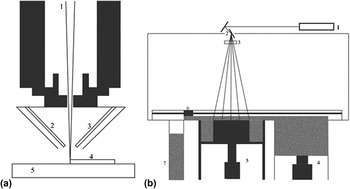
Additive Manufacturing (AM) is a group of technologies that builds near net shaped components by a track-by-track, layer-by-layer method. There are two main approaches to the technology for metallic materials Reference Gu, Meiners, Wissenbach and Poprawe1 ; the Direct Metal Deposition (DMD) approach and the powder bed approach. In the DMD approach the substrate is melted by a heat source, which can be a Tungsten Inert Gas (TIG) torch, laser, or an electron beam, and when powder or a wire is fed into the melt pool, this melts, Fig. 1(a). This formed track of material is controlled in length and position by a computer robotic system. Tracks of material are placed side by side in such a fashion as to build a layer of a desired shape. The next layer is then built on top of the previous layer and this is repeated until the component has been built. The major limiting factor with this technology is that overhanging features cannot be produced. The powder bed approach uses a substrate plate initially, which sits on a table that can be moved vertically, Fig. 1(b). A layer of powder is swept over the substrate (typically as thick as the powder being used) and is melted to the substrate. The heat source is computer controlled and the layers are melted in such a fashion that a layer of the part is produced much like the DMD technology. The bed is then lowered and a new layer of material is swept over. The heat source then melts the next layer together. This is repeated until the desired part is built. The advantage of this technology over DMD is support structures can be built allowing for overhanging features to be produced. Also the dimensional accuracy of this approach is superior.
Schematics of AM processes showing the key components; (a) DMD where (1) the laser beam, (2) nozzle shielding gas, (3) powder feeding nozzle, (4) deposited track, (5) substrate; (b) selective laser melting (SLM) where (1) laser, (2) double rotating mirror system, (3) beam focus lens, (4) powder feeding system, (5) building platform, (6) recoater, (7) powder recovery/recycle.

One of the strengths of AM processes is their low cost for producing prototypes or low volume production runs of metallic components. This has led to applications in aerospace, Reference Arcella and Froes2,Reference Brice and Hofmeister3 rapid tooling, Reference Vayre, Vigna and Villeneuve4 and biomedical implants. Reference Murr, Quinones, Gaytan, Lopez, Rodela, Martinez, Hernandez, Martinez, Medina and Wicker5 The other major strength of AM is the production of complex shapes such as spline curves, hollow sections, and lattice structures, Reference Tsopanos, Mines, McKown, Shen, Cantwell, Brooks and Sutcliffe6 which is changing the way components can be designed. Another advantage of AM DMD technology is the production of parts made from dissimilar materials such as copper backed tool steel for increasing cycle times in die casting and injection molding. Reference Imran, Masood, Brandt, Bhattacharya and Mazumder7 The production of tooling using AM draws on many of the advantages of AM and as such is the topic of this investigation.
H13 tool steel is one of the most commonly used tool steels for producing die casting and forging dies. The production of these dies involves the machining of the dies from large blocks of material after which a heat treatment is used to achieve the full strength of the material. This process is costly and time consuming and AM offers the ability to reduce the amount of machining and hence wastage of this expensive material. DMD is the main technology that has been used to produce blocks of material for evaluation of the process. Hofmeister et al. Reference Hofmeister, Griffith, Ensz and Smugeresky8 evaluated the effect of laser parameters on the thermal aspects of the processing, in particular, the cooling rate and its effect on the microstructure. It was found that the cooling rate produced by the DMD process for H13 is around 3 K/s, which is quite fast and as such produces a cellular microstructure. For the range of laser parameters tested, the dimension of the cellular structures only varies by several micrometers. Maziasz et al. Reference Maziasz, Payzant, Schlienger and McHugh9 evaluated the residual stress of spray formed and DMD deposited H13 and found that a tensile stress is produced during DMD in the deposited region, which was balanced with a compressive stress in the substrate. It was also noted that the DMD process produced an over tempering of the previous tracks, which is undesirable. Pinkerton and Li Reference Pinkerton and Li10 evaluated the effect of the powder morphology on the deposition of H13 and found that the main difference was a rougher surface finish for the water atomized powder due to its irregular shape. Spray forming of H13 has also been studied Reference McHugh, Lin, Zhou and Lavernia11 and it was found that process parameters influenced the microstructure produced, but more importantly, the compressive residual stress state of the formed material increased tool life due to its ability to resist fatigue cracking.
An understanding of residual stress formation in DMD AM is still lacking. To date much of the work has focused on simple structures such as walls Reference Moat, Pinkerton, Li, Withers and Preuss12–Reference Rangaswamy, Holden, Rogge and Griffith14 and square pillars. Reference Rangaswamy, Griffith, Prime, Holden, Rogge, Edwards and Sebring13,Reference Chen, Conlon, Xue and Rogge15 The residual stress is compressive in the center of all these structures and tensile is near the edges for both Waspaloy and stainless steel. A comparison between the wall and the pillar Reference Rangaswamy, Griffith, Prime, Holden, Rogge, Edwards and Sebring13 reveals that the magnitude of the stress does not change significantly and the distribution of stress is dictated by the geometry, which can be linked to the cooling rates. For H13 there has been a comprehensive study of residual stress, including full thermal and mechanical modeling of the process, Reference Ghosh and Choi16 that were compared with experimental results. However, an agreement between the experimental results and modeling was missing. The difference can be attributed to the fact that the effect of transformation plasticity and tempering of the microstructure were not taken into account in the model. It is clear that H13 tool steel residual stresses are important for their use in making forming dies from a fatigue point of view, this appears to be connected to the microstructure produced. These effects on a simple 3D build/component have not been evaluated and this is the next step in developing the technology for this material/application.
II. EXPERIMENTAL
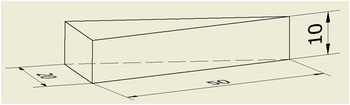
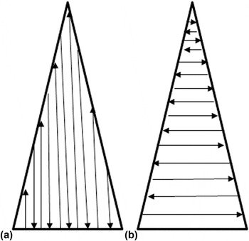
A POM DMD 505 equipped with a 5 kW CO2 laser was used to manufacture the H13 tool steel wedge shape, Fig. 2. The STEP file of the wedge was open in the DMD CAM software where a raster strategy was produced. The 90° cross-hatched path was used, Fig. 3, where the raster moves through 90° between each layer, as this has been found to produce good material properties by the equipment manufacturer. The DMD processing parameters use a laser power of 2500 W, a traversing speed of 300 mm/min, and a powder feed rate of 4.5 g/min. These parameters were developed in a previous trial and produced track dimensions of 2 mm in width and 1 mm in height. Two layers were deposited sequentially followed by a 5 min interval, which was repeated six times giving a build height of 12 mm.
Dimensions of the AM wedge in mm.

Schematic of raster pattern used in the production of H13 wedge with the DMD system; (a) initial raster pattern, (b) alternate raster pattern.

Residual strain through-sample-thickness scanning was carried out by neutron diffractometry at ANSTO in Kowari, NSW, Australia. The residual stress of the wedge was measured down its center thus allowing for the influence of section thickness to be resolved as a function of position. Three cross-sections were measured to ascertain the distribution of stress across the wedge and were also used to derive the variation of d0 (the unstrained lattice parameter) based on a stress balance. A 6 × 15 grid of measurement points were used across the length of the wedge, a 7 × 6 grid across the end of the wedge, a 5 × 6 grid 2/3 of the total length of the wedge, and a 3 × 6 grid in the front section of the wedge. A gauge volume of 2 mm was used to measure each point, and the wave length for the measurement was adjusted in such a way that the (311) reflection could be used for the stress measurement because this plane gives the best diffraction signal. Each point in the sample was measured in three orientations, thus allowing the calculation of the stress in three orthogonal orientations of the wedge.
Microstructural characterization was carried out by sectioning the sample along the long axis in the same orientation as the main neutron diffraction measurements. The sample was then ground flat to a 600 grit size and the microhardness measurements were conducted. A map of the hardness was developed by taking microhardness measurements every 0.5 mm through the thickness of the sample and 1 mm along its length. A load of 500 g was used to make the hardness impressions. The sample was then ground and polished down to 0.5 µm using colloidal silica. To reveal the microstructure the sample was etched in 5% Nital solution for 5 min. The microscopic image was taken using a digital camera set up on a stage where the height could be adjusted. Scanning electron microscopy (SEM) was conducted on a field emission gun microscope using the secondary electron detector. Images were taken to show the changing microstructure as a function of position through the sample.
Temperature measurements were taken using K type thermocouples supplied by Omega. To ensure a fast response time of the thermocouple a 0.005 mm gauge wire was used. The two wires were spot welded together and inserted into a 1.5 mm OD alumina tube. Holes 1.5 mm in diameter were drilled into the back of the mild steel substrate 2 mm from the top surface. A thermally conductive ceramic glue was placed on the end of the thermocouple and alumina sheath and pushed into the hole to attach the thermocouple to the plate. Three thermocouples were used and spaced 15 mm apart where the central thermocouple was placed in the middle of the wedge, thus allowing the temperature in the different regions of the wedge to be monitored simultaneously. The data were logged using Data Translator data logger model number DT302. The data were logged at 200 points/s where each data set ran for 10 min.
III. RESULTS AND DISCUSSION
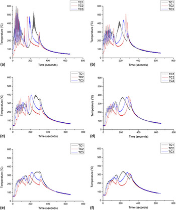
Figure 4(a) shows the temperature measured with the three thermocouples for the first two layers built. In the first layer the raster of the laser is up and down the length of the wedge, Fig. 3(a), hence there is a large variation in the thermal profile as the laser passes the three thermocouples. Initially the laser starts at the rear corner (the thick end) of the wedge and builds parallel to the thermocouples. Each time the laser passes the thermocouple the temperature rises and quickly decreases due to cooling from the substrate. The peak temperatures reached increases from track to track up to the point where the laser runs over the thermocouples. Beyond this point the laser is moving away from the thermocouples, therefore, a decrease in the peak temperature is observed because the heat has further to travel to reach the thermocouples which increases thermal losses due to the thermal resistance of the material. The peak temperature reached is around 600 °C, which is reasonable given that the thermocouples were 2 mm below the top of the substrate. By the end of the first layer the average temperature in the block has reached 150 °C, which is not that significant in terms of its effect on the microstructure. The laser then puts a track of material around the edge of the build to increase dimensional accuracy, which produces the second small trend in the temperature data.
Temperature measurements in three thermocouples placed 2 mm below the surface of the substrate, where the central thermocouple was positioned in the middle of the wedge and the other two were 15 mm either side; (a) layers 1&2; (b) layers 3&4; (c) layers 5&6; (d) layers 7&8; (e) layers 9&10; (f) layers 11&12.

The laser then moves to the tip of the wedge and starts to build in an orthogonal orientation, Fig. 3(b). The thermocouple near the tip immediately spikes due to it being close to the tip and then falls as the laser moves down the wedge away from the thermocouple. Because the wedge is thinner at the tip, the rate at which it moves down the wedge decreases with processing time. Therefore, as the laser approaches the middle thermocouple, the temperature begins to rise more gradually than the previous thermocouple measurements when the laser is on top of the thermocouple, and cools as the laser moves away. The rate of cooling is slightly slower than the central thermocouple because the length of the tracks increases with the wedge thickness, and hence more heat is put into the structure reducing the cooling rate. The laser then approaches the thermocouple in the thick section. Like the middle thermocouple its temperature rises due to the heat from the approaching laser at a rate that is slower than the middle thermocouple. This is due to the increasing length of the tracks as the wedge thickens. Small spikes appear in the thermocouple data as the laser passes the thermocouple similar to the temperature profiles of the previous layer. The laser then deposits a track of material around the edge of the wedge, which leads to the final thermal temperature excursions. The sample was then cooled for 5 min after the two layers resulting in the temperature decay.
The trends in the thermal data are essentially the same for Figs. 4(b)–4(f) with the only difference being that with each increasing layer the distance between the thermocouple and the laser increases. The major effect this has on the measurement is that it decreases the peak temperature reached due to thermal resistance of the material. This effect increases as the number of layers increases and it is due to the heat from the laser diffusing from the meltpool. This produces a more even temperature as the heat from the different points combines and the thermal resistance of the material decreases the temperature measured. Interestingly by the fifth layer the average temperature reached and stabilizes at around 200 °C for the rest of the build. The fact that the temperature remains elevated even in the substrate during the build would be the cause of the tempering in the microstructure observed.
Potentially the temperature in the wedge would be higher and perhaps would exceed the tempering temperature of H13 of 565 °C. The thermal excursion of the first layer only reaches a maximum temperature of 600 °C, which is low considering that the melting point of H13 is around 1430 °C, depending on composition. The steep temperature gradient is due to the low thermal conductivity of H13 (24.5 W/m K). This illustrates the very localized heating during DMD processing. This coupled with the complex thermal excursion the underlying material experiences makes the analysis of the temperature reached in the wedge difficult to calculate without the use of a complex finite element model, which is beyond the scope of this study.
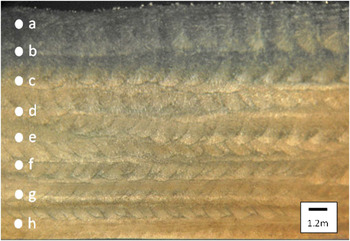
The macroscopic image of the cross-section of the H13 wedge is shown in Fig. 5. The pattern in this image alternates, which is a result of the change in raster orientation between layers. Essentially one layer is the track in cross-section and the next is the track along its length. It is also noticeable that the top layer has a different hue to the rest of the sample, which is due to the fact that the top region of the samples did not etch as much as the layers below, which can be attributed to a changing microstructure. The white dots labeled a to h indicate the position of the SEM images in Fig. 5.
Macroscopic image of H13 tool steel wedge in cross-section where the image was taken in the central cross-section of the wedge. The dots on the image indicate the regions where close up SEM images were taken.

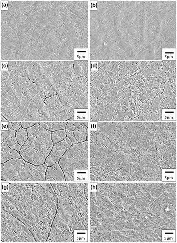
SEM of the etched microstructure in Fig. 6 shows how the microstructure changes with position from the top of the wedge. The top layer shows a very fine martensitic microstructure, which appears to have regions of retained austenite between the martensite laths. This has not been confirmed with x-ray diffraction. This is a reasonable assumption, however, as H13 has a very low martensitic transformation temperature. Reference Ghosh and Choi16 Figure 6(b) shows a coarsening of the microstructure but essentially the microstructure is still the same. Figure 6(c) shows that the microstructure has coarsened further and is dominated by martensitic laths, implying that the retained austenite in the other images has been transformed. The formation of austenite and its subsequent transformation to martensite in tool steels by the heat from a laser was observed by Colaco and Vilar. Reference Colaco and Vilar17 This is a reasonable assumption since this material has spent time at elevated temperature. Figure 6(d) shows that some of the martensite in the structure is being broken down and is similar to a microstructure of tempered H13 where carbide precipitation has occurred. Figures 6(e)–6(h) all show this tempered microstructure with prior austenite grain boundaries evident, which suggests the temperature in this region of the billet is lower and has less impact on the structure.
SEM of the H13 tool steel wedge taken from the central cross-section. The positions of the images correspond to the position of the white dots in Fig. 5.

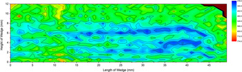
The hardness map shown in Fig. 7 supports the changing microstructure discussed above. The hardness of the top of the wedge is consistent at between 580 and 650 Vickers and corresponds to the dull region of the macroscopic image of Fig. 5. The coarsening of the microstructure and the transformation of the austenite to martensite with increased depth in this top zone negates each other in terms of mechanical properties, resulting in this region having consistent hardness with changing microstructure. At between 6 and 8 mm the hardness drops off significantly down to as low as 278 Vickers, which is the hardness of fully annealed microstructure. 18 This reduction in hardness is exaggerated near the top of the wedge where it is conceivable that a high temperature has been reached due to the smaller cross-section of the material. Beyond this the hardness is relatively unchanged, which is consistent with the microstructure not changing and suggests that temperatures reached in the initial layers are not enough to change the microstructure further due to the heat from the upper layers. This result emphasizes the fact that the section thickness does play a role in the mechanical properties produced, particularly when the microstructure can transform due to heat.
Micro-Vickers microhardness map of H13 tool steel wedge, measured in the central cross-section, where the start of the hardness map is the thick end of the wedge.

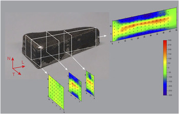
The residual stress distributions for the H13 wedge are shown in Fig. 8. The distribution of stress is not symmetrical like a quenching stress, Reference Cottam, Luzin, Liu, Wong, Wang and Brandt19 in that the side walls of the wedge are not in compression and the size of the compression zone in the top and bottom regions of the wedge does not match in depth. The compressive stress is around 250 MPa in magnitude in both the top and bottom regions and there is a thin band of tensile stress just above the central region of the sample that is around 150 MPa in magnitude. However, the stress distribution is compressive near the top and bottom surface and tensile near the center, which is the opposite to that reported by other investigations. Reference Moat, Pinkerton, Li, Withers and Preuss12,Reference Rangaswamy, Holden, Rogge and Griffith14,Reference Chen, Conlon, Xue and Rogge15 They found the opposite trend where the center was in compression and the surface was in tension like an inverse quench.
Residual stress map of H13 tool steel wedge showing results of four different orientations where measurements were made. The units of the scale are MPa.

The compressive stress at the very top of the wedge can be attributed to the low martensitic transformation temperature of this steel. Reference Ghosh and Choi16 It is well known in the welding literature that steels with a low martensitic transformation temperature produce compressive residual stresses in their martensitic regions. The formation of the compressive stress is due to the contraction (dilation) of the material during the transformation. Reference Murakawa, Beres, Davies, Rashed, Vega, Tsunori, Nikbin and Dye20 When this occurs at a low temperature tensile stresses that have formed during cooling are either reduced or they become compressive. The final stress magnitude and sign depends on the thermal expansion of the material, the size of the dilation component of the transformation, and the elastic modulus of the material. Reference Withers and Bhadeshia21 This phenomenon is the cause of the compressive residual stress in the top layer of the wedge. Then further down it was observed that retained austenite was transforming to martensite again, and this transformation exerts a compressive stress on the structure resulting in the region of compressive stress existing up to 2 mm into the structure. This corresponds to the dull region of the macrostructure in Fig. 5.
The residual stress then transitions into a tensile residual stress just above the center of the wedge. This region corresponds with the change in hardness and also the tempering of the microstructure. Essentially the tempering of martensite to form ferrite and iron carbide causes tension in the microstructure due to the lattice spacing decreasing with the precipitation of the iron carbide. Reference Novelo-Peralta, Gonzales and Lara-Rodriguez22 No further microstructure changes occur and as such, the stress transitions back to compressive to balance the tensile stress in the center of the wedge. Due to the layered nature of the wedge construction, the stress in plane is largely unaffected by the metallurgical transformations and therefore the changes in residual stress occur in the N direction and not the L and T directions, Fig. 8.
The residual stress distribution of the wedge is the opposite of that found in other studies where the center was in compression and the exterior was in tension. The work of Moat et al. Reference Moat, Pinkerton, Li, Withers and Preuss12 used Waspalloy, which does not undergo a martensitic phase transformation during cooling and has very low thermal expansion and conductivity. Rangaswamy et al. Reference Rangaswamy, Griffith, Prime, Holden, Rogge, Edwards and Sebring13,Reference Rangaswamy, Holden, Rogge and Griffith14 evaluated Inconel, another nickel based alloy, and austenitic stainless steel, both of which do not undergo a martensitic phase transformation during cooling. Therefore, the residual stress produced is due only to the cooling of the component once built. As confirmed by the finite element modeling of Wang Reference Wang, Felicelli and Pratt23 this is the cause of the residual stress distribution observed in these studies. However, as shown above there are three metallurgical factors that influence the residual stress distributions formed in the H13 wedge, which have a greater influence on the residual stress formed than just the cooling rate alone being the cause of the residual stress distribution of the previous studies.
The wedge shape of the construction has had almost no effect on the residual stress distribution formed, which is illustrated by the fact that the magnitude and sign of the residual stress changes in the N orientation and not the T and L. Again this supports the explanation that the stresses have arisen due to metallurgical effects, which are consistent through the different layers of the material. However, the hardness map in Fig. 7 shows that tempering effects are more pronounced at the tip of the wedge than the thick end of the wedge. This can be attributed to the temperatures reached in the tip of the wedge being higher for longer compared to the thick end. This is reasonable as the volume of material is small and as such requires less energy to be heated. Also the heat has a smaller area to diffuse into, which also acts to increase the temperature in the thinner sections. This suggests that perhaps lower laser powers should be used to produce thin sections of H13 by DMD.
The high hardness in the top 4 mm of the wedge is higher than the strength typically developed during heat treatment and post-machining in conventional manufacturing. Therefore, it is possible to use the tool steel in the as-deposited condition, hence removing the heat treatment step and saving time and money in production. The compressive stress in this top layer is also desirable as this will resist fatigue of the die during service, adding another advantage over the traditional machining method. However, tempering of the structure below a 4 mm depth is undesirable. Perhaps this could be avoided by making the bulk of the die with a cheap material like mild steel and then using H13 for the final 4 mm of the die. While this idea needs to be proven, it would considerably benefit AM production of tool steel dies over conventional machining and heat treatment.
IV. CONCLUSIONS
Characterization of the H13 tool steel wedge has revealed the complex relationship between the effect of heat from the laser, the metallurgical characteristics of the H13, and their effects on the microstructure and residual stress formed. The compressive stress state at the top of the wedge can be attributed to the low martensitic transformation temperature of the H13 material. The significant depth of the compressive stress region was attributed to retained austenite transforming to martensite due to the heat from the laser. The region of tensile stress was attributed to the martensite being tempered by the heat from the laser causing the carbon trapped in solution to precipitate out as iron carbide. While the residual stress was not influenced by the geometry, the tempering of the H13 was. It was suggested that lower laser power levels should be used to produce thin sections of H13. The as-deposited hardness and the compressive stress state in the top 4 mm of the wedge are ideal for use in die casting and forging dies and this illustrates the potential of the AM process as a method to produce tooling.
ACKNOWLEDGMENTS
The authors would also like to thank Mr. Girish Thipperudrappa for his help with conducting the DMD experiments, Mr. Andrew Moore for his help with the thermal measurements, and AINSE for supplying funding for neutron proposal 2747.