1. Introduction
1.1. Brief
Unmanned aerial vehicles (UAVs), particularly multirotors, have been widely deployed across a spectrum of applications. Conventional UAVs, however, are predominantly designed for aerial operations, lacking the capability to traverse terrestrial or aquatic environments effectively. Consequently, operating standard UAVs in unstructured or confined environments remains a formidable challenge [Reference Elmokadem and Savkin1]. In contrast, multi-domain multirotors (MDMs) exhibit substantially broader utility [Reference Kawasaki, Zhao, Okada and Inaba2]. Their adaptability to multiple operational domains enhances robustness in unpredictable scenarios – such as adverse weather, complex terrains, and cluttered indoor settings like disaster zones – while also benefiting from reduced energy consumption during ground or water-based locomotion compared to flight.
Although several reviews have briefly noted the emergence of adaptable multi-domain UAVs [Reference Darvishpoor, Roshanian, Raissi and Hassanalian3–Reference Meng, He and Han5], there is a notable scarcity of dedicated surveys that comprehensively address MDMs. In particular, detailed studies focusing on the mechanical design of such systems are largely absent from the literature. As observed, the structural layout of MDMs frequently diverges from that of conventional UAVs, in some cases incorporating more sophisticated mechanisms to accommodate multi-domain mobility. These designs vary extensively in complexity and integration strategies.
This survey concentrates notably on cross-domain multirotors. It represents one of the few efforts to systematically analyze and synthesize mechanical design principles emerging in recent MDM research, thereby providing a focused foundation for future developments in this discipline.
1.2. Notices
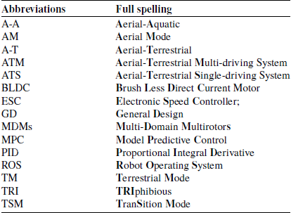
As detailed in Table I, the abbreviations used in this survey are as follows.
Frequently used abbreviations in this survey.

This survey also serves as foundational work for the author’s ongoing MDM project, “AMOEBA” [Reference Kunlun, Zheng, Xia and Vlasov6], which aims to develop an amphibious (potentially triphibious) robot based on a single propulsion system. The authors classify “AMOEBA” as a multi-wheeled structure driven by a unified propulsion unit. The design objective is to enhance functional versatility while maintaining structural simplicity.
1.3. Classification methods of the MDMs
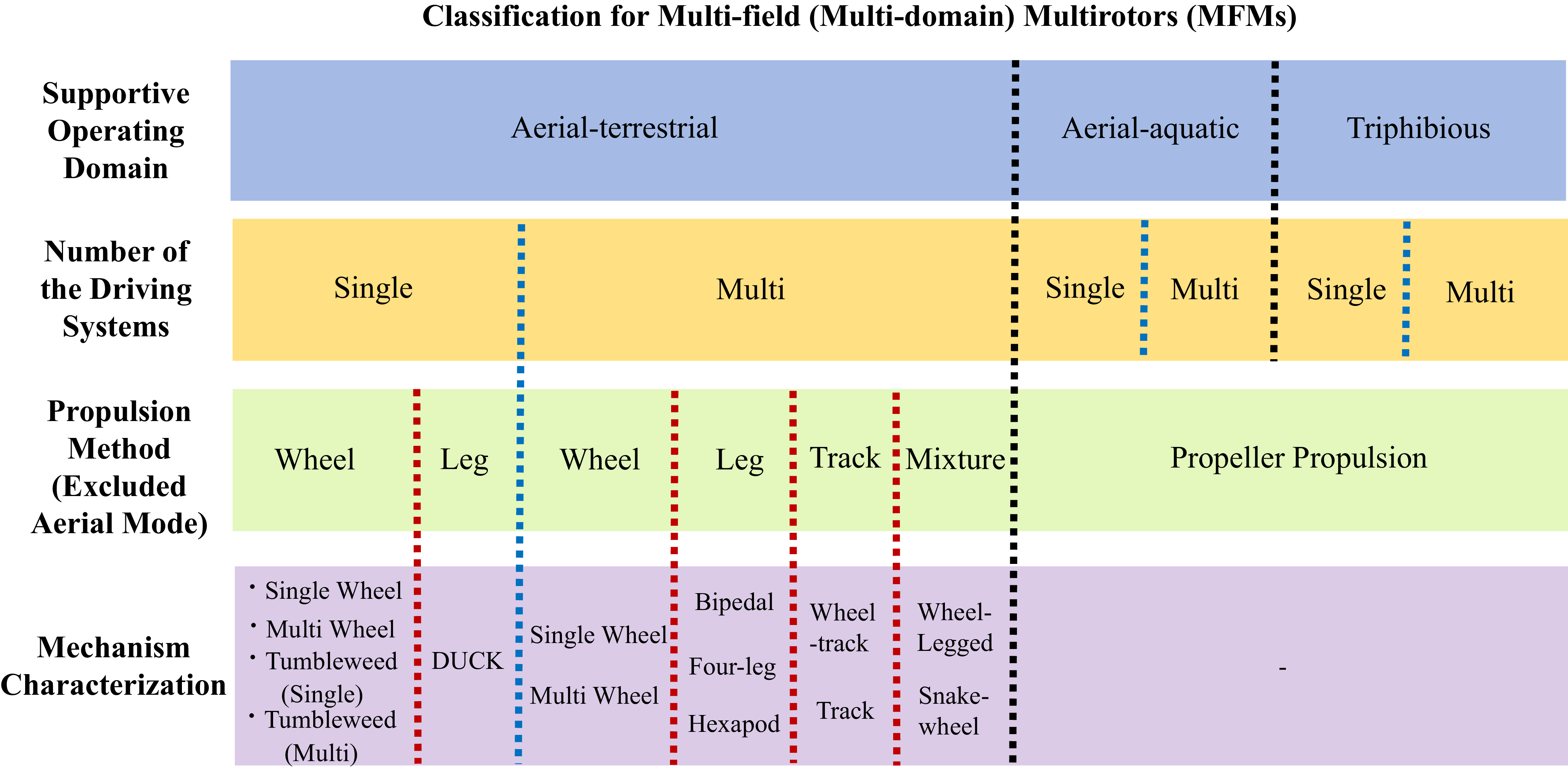
MDMs are categorized primarily by their operational media. Secondary classification is based on the number of distinct drive systems, followed by a third level focusing on propulsion methods across different domains, noting that all systems employ multirotors for aerial locomotion.
Following the organizational framework of [Reference Darvishpoor, Roshanian, Raissi and Hassanalian3], this survey adopts an expanded sectional structure as illustrated in Figure 1. Emphasis is placed on aerial-terrestrial MDMs, which have received the most extensive research attention.
The survey is structured as follows: General design for all MDMs are presented in Section 2. Section 3 addresses aerial-terrestrial MDMs; Section 4 covers aerial-aquatic systems; Section 5 discusses triphibious MDMs; Section 6 introduces the overall designs of electrical systems of these MDMs; Section 7 analyzes current limitations and proposes future research directions; and Section 8 provides concluding remarks. A detailed outline of Sections 3–5 is provided in Figure 1.
Content of this survey.

Figure 1 Long description
The table categorizes multi-field multirotors (MFMs) based on their supportive operating domain, number of driving systems, propulsion method, and mechanism characterization. The operating domains include aerial-terrestrial, aerial-aquatic, and triphibious. The number of driving systems is divided into single and multi. Propulsion methods for terrestrial modes include wheel, leg, track, and a mixture, while aerial modes use propeller propulsion. Mechanism characterization details various configurations such as single wheel, multi wheel, bipedal, four-leg, hexapod, wheel-track, wheel-legged, snake-wheel, and more. The table provides a structured overview of how different multirotors are designed to operate across multiple environments.
1.4. Contribution
This survey places emphasis on studies that have developed functional prototypes, premised on the understanding that theoretical models alone may not fully capture the practical intricacies of implementation. While the authors have endeavored to include all relevant publications, several may have been inadvertently omitted. Nonetheless, this survey offers a broad yet systematic overview of the current landscape in MDM research, with a particular focus on mechanical architectures. Detailed dynamic and kinematic analyses are beyond the scope of this work and are reserved for future research.
The emphasis on mechanical design stems from its fundamental role in MDM development. This survey highlights notable (and potentially instructive) mechanical innovations reported across the literature. Given that these structures are usually obscure and complicated to interpret individually, this survey synthesizes them under a unified framework to facilitate comprehension. Where appropriate, the authors provide simplified, consistently styled renderings to intuitively illustrate crucial mechanisms, with the aim of supporting reproducibility and further development. Critical factors such as complexity, stability, and manufacturability are considered throughout. Moreover, certain original figures and annotations from cited works have been refined to improve clarity and emphasize salient design features.
Hence, all figures in this survey are delivered in scalable vector format (PDF) to retain clarity when viewed at higher magnifications. Nevertheless, several original figures sourced from the literature are inherently of limited resolution, and the readers’ discretion is acknowledged. Additionally, to ensure consistency in presentation and to enhance clarity in identifying specific mechanisms – which may not have been explicitly annotated in the original publications – the author have reprocessed selected illustrations and annotations using image editing and typesetting software. Some labels and notes have been revised for uniformity and ease of interpretation and possibly therefore differ from those in the cited sources.
The focus on multirotor-based MDMs is motivated by several practical advantages. Multirotors are recommended as the preferred base platform for MDMs [Reference Zhong, Cao, Chai and Bai7], owing to their simpler control relative to fixed-wing systems [Reference Zhiyu8], ability to take off and land vertically with minimal space requirements, and potential for enhanced energy efficiency and obstacle negotiation through multi-domain power reuse [Reference Kalantari and Spenko9]. This approach – particularly the reuse of a single propulsion unit such as a brush less direct current motor (BLDC) motor across multiple domains – has been successfully demonstrated in several studies [Reference Zhu, Guo, Li and Wang10]. Furthermore, multirotor configurations facilitate miniaturization, a critical factor in cross-domain vehicle design [Reference Bai, Jin, Liu, Zeng and Lian11].
Additionally, an evaluation framework based on the analytic hierarchy process (AHP) is introduced to assist researchers in identifying the appropriate MDM designs for distinct usages.
2. General mechanical design of the MDMs
2.1. Excerpt of general design
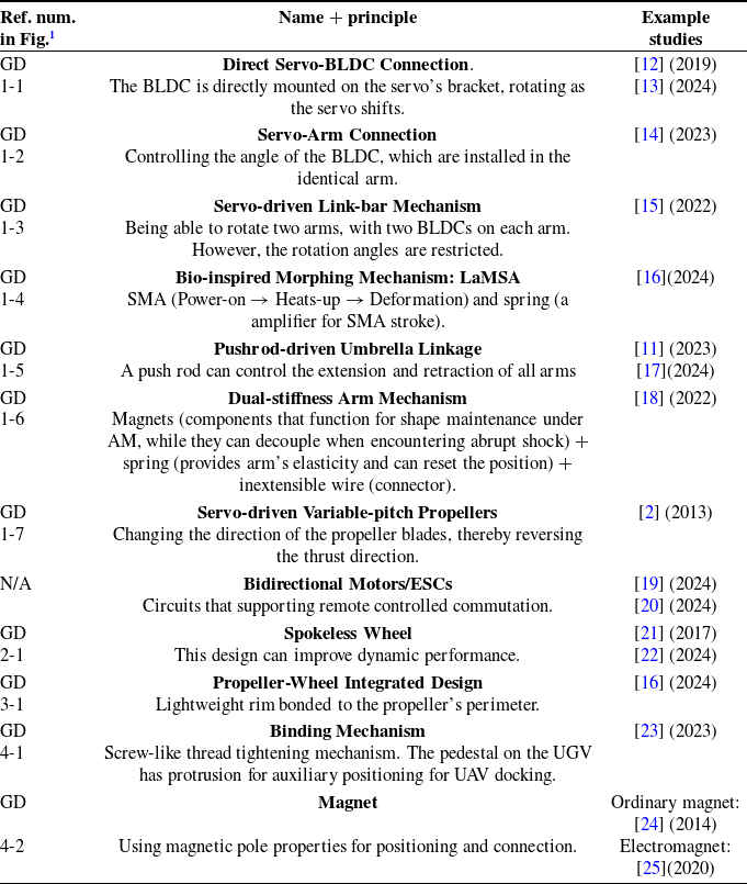
Both single-drive and multi-drive designs share generic characteristics, as summarized in Table II.
Mechanical design excerpt of general designs (GD).

Table II Long description
A table comparing various mechanical design principles and their example studies. The table has five columns: Reference Number, Name and Principle, Example Studies, and two additional columns for further details. It includes rows with specific design principles such as Direct Servo-BLDC Connection, Servo-Arm Connection, Servo-driven Link-bar Mechanism, Bio-inspired Morphing Mechanism, Pushrod-driven Umbrella Linkage, Dual-stiffness Arm Mechanism, Servo-driven Variable-pitch Propellers, Bidirectional Motors/ESCs, Spokeless Wheel, Propeller-Wheel Integrated Design, Binding Mechanism, and Magnet. Each row lists the reference number, the name and principle of the design, and the example studies with their respective years. The table provides a comprehensive overview of different mechanical designs and their applications.
1 GD 1-X: Frame Reconfiguration Mechanism Thrust Vector Control.
GD 2-X: Ground Movement.
GD 3-X: Aerial-terrestrial Coupling.
GD 4-X: Docking Module.
These are relatively general designs. The corresponding figures are shown as follows.
Figure for the mechanical design excerpt of general designs (1/3).

Figure 2 Long description
The image consists of multiple elements, including photos and diagrams, showcasing different prototypes and designs of multi-domain multirotors. The first section features two prototypes: Prototype I, which includes a drone with a tilt servo mechanism, and Prototype II, which shows a drone with a sprawl movement mechanism. The second section displays a prototype with a hardware overview, detailing the components and their connections. The third section includes a 3D model of a drone with a link-bar mechanism and diagrams illustrating the sprawl movement and servo angle. The fourth section presents a rendering of the bistable LaMSA system, showing the shifting procedure and a force diagram side view of the morphing system.
Figure for the mechanical design excerpt of general designs (2/3).

Figure 3 Long description
The image presents a detailed diagram of the mechanical design of adaptable multi-domain unmanned aerial vehicles (UAVs). It includes multiple sub-diagrams labeled GD 1-5, GD 1-6, and GD 1-7, each depicting different aspects of the UAV's structure and functionality. The first sub-diagram (GD 1-5) shows the arm motivation mechanism and PVBS cooperation process, illustrating the arm in fully expanded, transforming, and totally folded states. The second sub-diagram (GD 1-6) focuses on the dual-stiffness mechanism, highlighting components such as magnets, inextensible wire, and spring, along with the top view of the quadrotor under different configurations: nominal, partially folded, and compact. The third sub-diagram (GD 1-7) demonstrates the increase and decrease of pitch, with arrows indicating the movement of the link-bar mechanism and the propeller. The diagram also includes detailed views of the arm foldable and self-deployable mechanism, showing the drive base, hinged support, torsion spring, and connecting rod.
Figure for the mechanical design excerpt of general designs (3/3).

Figure 4 Long description
The image consists of multiple elements, including photos, diagrams, and illustrations, showcasing different mechanical designs and prototypes. The first element is a photo of a drone prototype with a frame, spoked wheels, and a roller. The second element is a cross-section view diagram of the drone's design, labeled with parts such as the frame and roller. The third element is a photo of a propeller prototype with a polycarbonate rim, cyanoacrylate adhesive, and a commercial propeller. The fourth element is a diagram of an electromagnet and a matrix of ordinary magnets, showing the docking arm and docking face. The fifth element is a photo of a separated prototype with spiral landing gear and a pedestal, along with a guiding surface. The sixth element is a photo of an assembled prototype. The seventh element is a diagram of the binding system, showing the interaction between the spiral landing gear and the guiding surface.
2.2. AHP analysis based on GD 1-1 to GD 1-7
To evaluate the scores of various frame-reconfiguration methods, designs GD1-1 to GD1-7 are taken as examples. This evaluation sample can be regarded as a preliminary reference to evaluate other designs.
Six evaluation criteria are defined: conciseness, integrity, energy consumption, functionality, reliability, and weight. A preliminary assessment using the AHP is applied to score these designs.
The definitions of these six metrics are as follows:
-
• Conciseness: Refers to structural and control simplicity, which often correlates with lower development cost and reduced operational complexity.
-
• Integrity: Denotes the degree of integration with the MDM airframe, influencing overall aerodynamic performance and structural coherence.
-
• Energy Consumption: Indicates power usage efficiency. Due to severe constraints in onboard battery capacity, energy-efficient design is critical.
-
• Functionality: Evaluates whether the design offers additional capabilities beyond its primary intended functions.
-
• Reliability: Reflects structural robustness and durability under repeated operation cycles.
-
• Weight: As MDMs belong to the UAV family, weight directly impacts takeoff capability, flight performance, and maneuverability.
The scoring employs a two-stage subjective AHP method, with the procedure as follows:
-
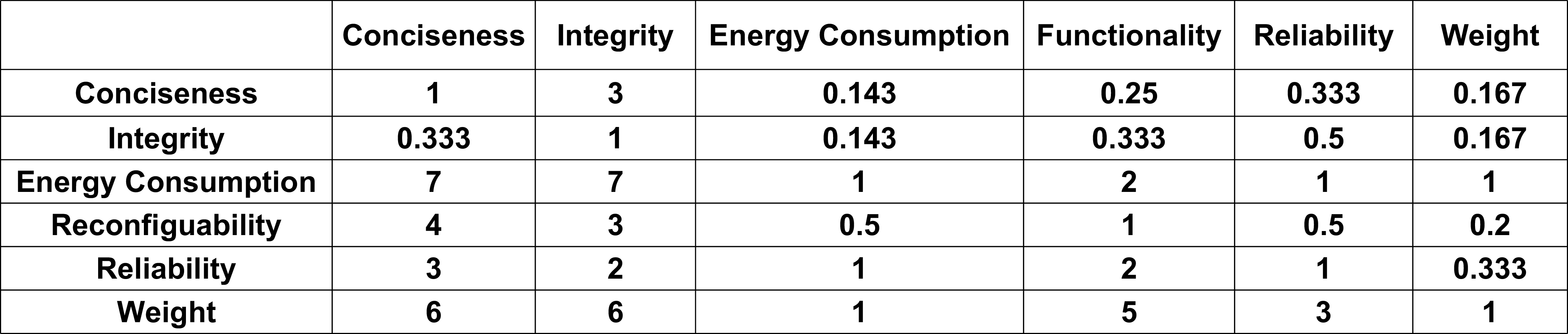
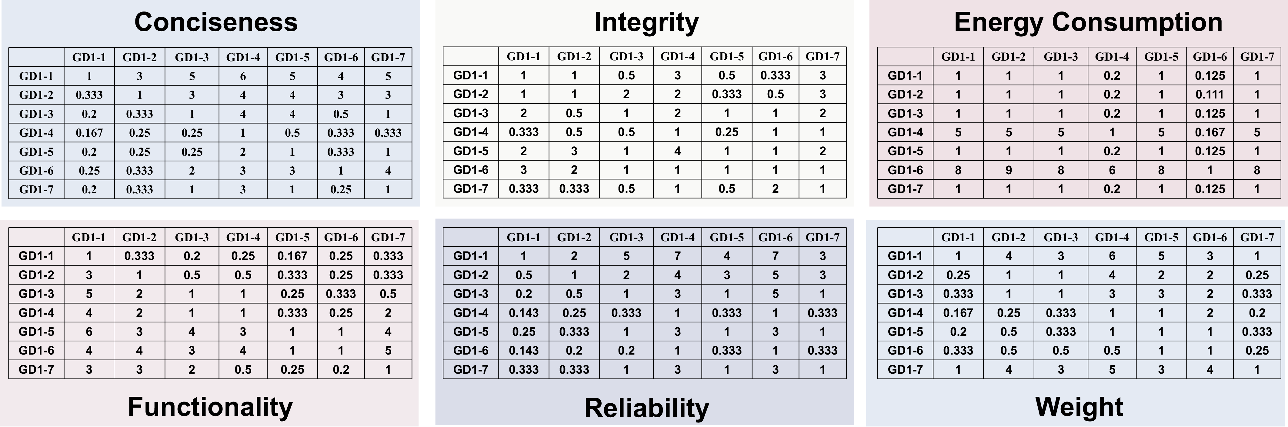
1. Establish the main criteria (priority comparisons among evaluation metrics), denoted as Matrix A, as shown in Figure 5.
-
2. Construct the alternative-level scoring (priority comparisons among designs under each metric), denoted as Matrix B, as shown in Figure 6.
-
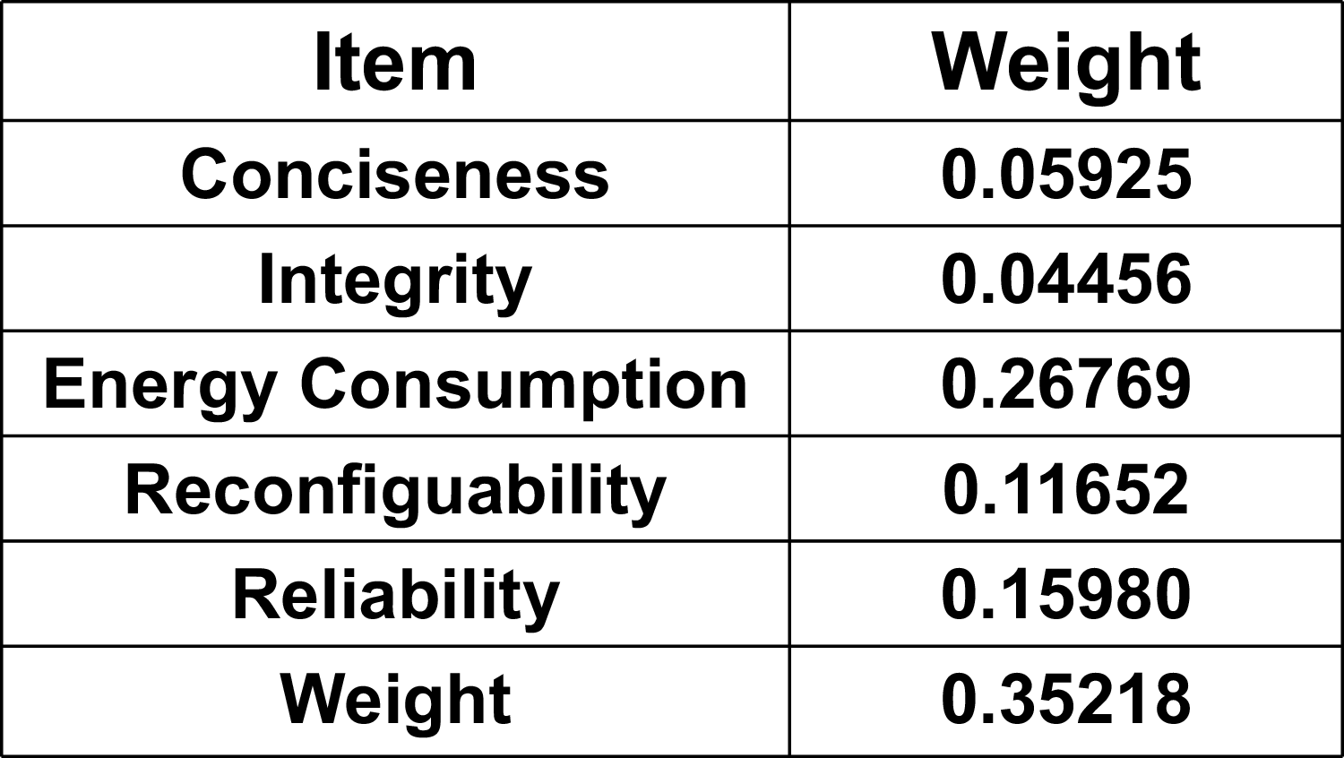
3. Validate the confidence of Matrix A and Matrix B using an online AHP solving platform (SPSSPRO), calculating the weights of each metric (as shown in the Figure 7) and the weights of designs GD1-1 to GD1-7 under each respective metric (as shown in the Figure 8).
-
4. Compute the overall weights for designs GD1-1 to GD1-7 using the formula
 $A^T \times B$
, yielding respective scores of (0.211, 0.117, 0.102, 0.295, 0.098, 0.214, 0.151).

The main criteria (Matrix A).

Figure 5 Long description
The table presents a comparison of various criteria including conciseness, integrity, energy consumption, reconfigurability, reliability, and weight. It consists of six rows and seven columns. The columns are labeled Conciseness, Integrity, Energy Consumption, Functionality, Reliability, and Weight. Each row represents a different criterion and contains values that compare it against the others. Notable values include high weights for energy consumption and reliability, indicating their importance. The table provides a detailed matrix for evaluating these criteria.
The alternative-level criteria (Matrix B).

Figure 6 Long description
The matrix presents correlation values between various criteria for evaluating a multi-wheeled amphibious robot design. It consists of six rows and six columns, each labeled with specific criteria such as Conciseness, Integrity, Energy Consumption, Functionality, Reliability, and Weight. The matrix is symmetrical, with correlation coefficients ranging from 0.2 to 1. Notable trends include high correlations between certain criteria, such as between Functionality and Reliability, and between Energy Consumption and Weight. The highest correlation values, indicated by 1, appear along the diagonal, representing self-correlation. The matrix provides a detailed comparison of how different criteria interrelate, highlighting the importance of balancing various factors in the design of an amphibious robot.
Weights (Matrix A_W) of the main criteria.

Figure 7 Long description
A table with two columns labeled Item and Weight, and seven rows. The items listed are Conciseness, Integrity, Energy Consumption, Reconfigurability, Reliability, and Weight. The corresponding weights are 0.05925, 0.04456, 0.26769, 0.11652, 0.15980, and 0.35218 respectively. The table provides a quantitative assessment of different criteria relevant to multirotor-based MDMs.
Weights (Matrix B_W) and confidences of the alternative-level criteria.

Figure 8 Long description
The table presents the weights and confidences of alternative-level criteria for items such as conciseness, integrity, energy consumption, reconfigurability, reliability, and weight. It includes seven columns for different criteria weights (GD1-1 to GD1-7), a column for Max Eigen, CI, and CR. Each row lists the values for these criteria. For example, the row for conciseness shows values like 0.37895 for GD1-1, 0.20978 for GD1-2, and so on, with a Max Eigen of 7.521, CI of 0.087, and CR of 0.065. The table provides a detailed comparison of how each criterion contributes to the overall assessment.
For detailed process derivation, please refer to Ref. [Reference Wu and Sergey26].
Based on the AHP results, the low-energy-consumption design GD1-4 achieved the highest ranking, while the passive design and the extremely streamlined servo-controlled arm received comparable scores.
It should be noted, however, that these results are suggestive rather than definitive. Each design possesses merits within its specific operational context. Selection should be based on particular application requirements. For instance, the lower-scoring GD1-5 is designed for amphibious use, which necessitates high-power thrusters (due to highly nonlinear effort caused by water resistance) and a waterproof housing – factors that inherently affect its score under the assigned criteria.
3. Aerial-terrestrial
3.1. Single -driving system
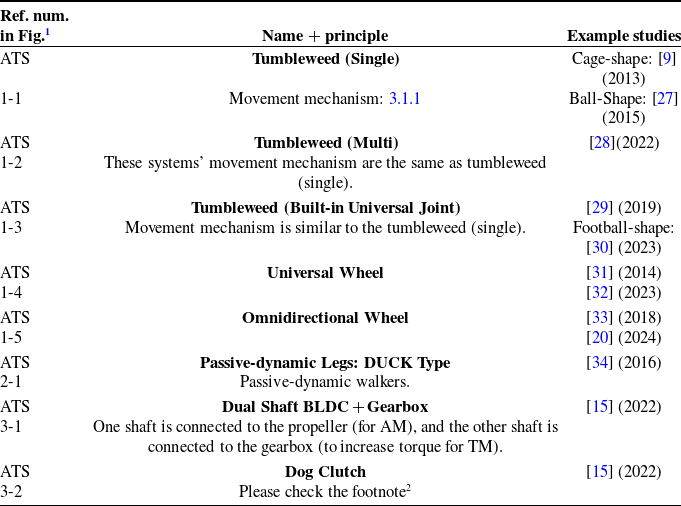
For A-T single-driving systems, the representative mechanical designs are summarized in Table III.
Mechanical design excerpt of aerial-terrestrial systems that use single-driving system (ATS).

Table III Long description
A table with three columns and eight rows detailing mechanical designs of aerial-terrestrial systems that use a single-driving system. The columns are labeled 'Ref. num.', 'in Fig.', 'Name + principle', and 'Example studies'. The table lists various designs such as Tumbleweed (Single), Tumbleweed (Multi), Tumbleweed (Built-in Universal Joint), Universal Wheel, Omnidirectional Wheel, Passive-dynamic Legs: DUCK Type, Dual Shaft BLDC + Gearbox, and Dog Clutch. Each design includes a reference number, figure number, name and principle, and example studies with years ranging from 2013 to 2024.
1 ATS 1-X: Chassis for Terrestrial Locomotion.
ATS 2-X: Passive Leg.
ATS 3-X: Coupling for Aerial-terrestrial Locomotion.
2 TM: Under the influence of the servo-driven linkage mechanism (referenced as Reference Kawasaki, Zhao, Okada and Inaba2), the arm rotates through a specific angle, thereby disengaging the fork. Subsequently, two clutches are decoupled by the action of the return spring, resulting in the decoupling of the BLDC from the propeller.
AM: The arm then reverts to its horizontal position, prompting the fork to be pushed in. This action depresses the clutch, facilitating re-engagement, and subsequently re-couples the BLDC motor to the propeller.
The corresponding figures are shown as follows
Figure for the mechanical design excerpt of aerial-terrestrial systems that employ single-driving system (1/2).

Figure 9 Long description
The image contains four diagrams showcasing different prototypes of aerial-terrestrial systems with single-driving systems. The first diagram on the top left shows Prototype 1 with a cage shape, highlighting components like the planar bearing, rolling cage, and shaft axle. The second diagram on the top right shows Prototype 2 with a ball shape, featuring a lightweight exoskeleton, perching surface, and axles with bearings. The third diagram on the bottom left illustrates a 3D model of two passive rotating hemispherical shells, including a gimbal shaft, sub-axis, and main axis. The fourth diagram on the bottom right displays Prototype 1 and Prototype 2 of the ATS 1-4 system, with components like bearings and axles clearly labeled.
3.1.1. Wheel
The operating principle of single-wheel drive systems is relatively straightforward: the thrust generated by the BLDC propels the UAV’s motion, which in turn drives the rotation of an outer shell connected to the airframe via bearings.
3.1.1.1. Single wheel
Gemini, introduced by Ref. [Reference Qin, Li, Wei and Zhang35], employs a dual-rotor system with a servo-actuated tilting mechanism for each motor. Terrestrial locomotion is facilitated by a single passive wheel. The design emphasizes energy efficiency and improved maneuverability, notwithstanding the inherent stability challenges associated with a dual-rotor platform. During TM, the system exhibits dynamics analogous to an inverted pendulum and is controlled using a terminal-sliding-mode controller. It should be noted, however, that the vehicle requires auxiliary support in stationary conditions to avoid tipping over.
Reference [Reference Pan, Jiang, Zhang, Xu and Gao32] introduced Skywalker, a quadrotor integrated with a passive omnidirectional wheel (see ATS 1-4 in Figure 9 (ii)). The platform is equipped with a Pixhawk 4 Mini flight controller and an NVIDIA Xavier NX module for onboard computation and state estimation. A unified cascaded control architecture, leveraging differential flatness transformation, serves as the primary strategy to facilitate smooth mode transitions and precise trajectory tracking. In TM, the system is modeled as a hybrid dynamical system with inverted pendulum characteristics, incorporating ground reaction forces and friction into the dynamics – thereby simplifying analysis compared to more complex strategies such as tumbling-based locomotion. Furthermore, the omnidirectional wheel design decouples yaw control from translational velocity control, significantly enhancing agility and trajectory tracking precision.
3.1.1.2. Multi wheel
The choice of wheel count depends on practical requirements. While several research described their designs as unicycles, certain implementations incorporate auxiliary wheels [Reference Zheng, Wang, Wu, Cai, Yu, Zhang, Tu, Meng, Lu and Gao36], while others utilize discrete, independently mounted wheels [Reference d’Andréa Novel and Thorel37]. In most cases, these systems’ wheels operate asynchronously, with speeds varying according to various terrains and control inputs. Moreover, their mechanical architecture differs substantially from that of conventional unicycles or two-wheel systems, complicating structural analysis and influencing subsequent dynamic and kinematic modeling.
For instance, although the design in Ref. [Reference Yang, Dong, Li, Zhang, Xiang, Li and Tu38] employs two sets of serially connected wheels with synchronized speeds, its stability characteristics distinguish it from typical dual-wheel configurations. Thus, it is classified as the four-wheel system. It should be noted that this categorization is adopted for organizational consistency within this survey and is not regarded as a universal standard. Analogous classification approaches are applied throughout subsequent sections. Common multi-wheel configurations include 2W, 3W, and 4W systems.
2W: A significant amount of research has focused on this configuration.
Reference [Reference Pimentel and Basiri39] presents an X-configuration quadrotor with passive wheels symmetrically mounted on both sides and develops a nonlinear motion controller for TM on inclined surfaces. The study provides a comprehensive dynamic and kinematic model of the proposed system and identifies critical design considerations for controlling such a MDM in TM.
Reference [Reference Zhang, Wu, Zhang, Xu and Gao40] proposes a quadrotor combined with dual wheels, focusing on enhancing autonomous navigation. The system employs a hierarchical safe motion planner to search for kino-dynamic terrestrial-aerial hybrid paths and refines them into safe, smooth, and dynamically feasible trajectories via B-spline optimization.
Reference [Reference Lin, Zhang, Pan, Xu and Gao41] introduces the Skater, a two-wheel design combined with a dual-rotor system (each arm has a servo to change the thrust direction). The NMPC (nonlinear model predictive control) controller is used. The paper asserts that dual rotors have superior steering capabilities than quadrotor design.
Reference [Reference Ding, Ji, Zhang, Zhu, Dong, Wu, Han and Yang42] introduces Chat-PM (Composite Hybrid Aerial/Terrestrial Precise Manipulator), which integrates conventional dual-wheel design, a quadrotor, and a 4-degrees of freedom (DOF) manipulator. This study predominantly focus on using a Moving Horizon Estimation-based estimator to stabilize the operation of the manipulator on surfaces with diverse inclinations. The control diagrams for AM and TM are also provided, along with force analysis and kinematic analysis due to the inclusion of the manipulator.
Reference [Reference Itasse, Moschetta, Ameho and Carr43] introduces the MAVion, a hybrid platform comprising dual rotors and dual wheels, with an emphasis on aerodynamic characterization of the airframe through wind tunnel evaluation. Although a prototype was constructed, no experimental results from terrestrial or multi-modal operation are reported.
3W: Reference [Reference Jeong and Jung44] introduces Flymobile, which features servos on each of its arms, with servo angles ranging from
 $0^\circ$
to
 $90^\circ$
. This design allows BLDC for forward propulsion in TM mode, with three passive omnidirectional wheels powered by differential thrust from the motors, enabling the vehicle to move flexibly. The system utilizes a non-model-based proportional integral derivative (PID) control approach.
Reference [Reference d’Andréa Novel and Thorel37] focuses on the mathematical analysis of the stability and control of peculiar mechanical systems (such as unicycle robots and sliders). With their analysis, the researchers proposed a experimental platform comprises a quadrotor and three omnidirectional wheels, forming a hybrid air-ground UAV. The paper delivers detailed mathematical modeling and analysis.
4W: This category has seen a similar volume of research to 2W, with more straightforward control strategies.
Reference [Reference Premachandra, Otsuka, Gohara, Ninomiya and Kato33] emphasizes fully autonomous aerial-ground operation, a concept that had not been explored before 2019. Additionally, the system uses a R8C-25 processor and IMAPCAR2 camera to obtain image data, which powers autonomous navigation and obstacle avoidance.
Reference [Reference Wilcox, Joyce and Bartlett16] is used for rescue operations, featuring a quadrotor combined with propeller wheels (polycarbonate rims and five-bladed bullnose propellers bonded with cyanoacrylate adhesive, as shown in GD 3-1, Figure 4), enabling both aerial and terrestrial operation. Compared to conventional propellers, the power loss is reduced by less than 10% which is an acceptable value. The LaMSA mechanism (Latch-mediated, spring-actuated morphing mechanism, as shown in GD 1-4, Figure 2), inspired by the mantis shrimp [Reference Longo, Cox, Azizi, Ilton, Olberding, St Pierre and Patek45] and the Myrmecia ant [Reference Zhakypov, Mori, Hosoda and Paik46], uses SMA (Shape Memory Alloy) wires, which shrink when heated, and spring-powered folding mechanisms to amplify the relatively small stroke of the SMA into a larger displacement. The mechanism works swiftly, with actuation occurring in approximately 120 milliseconds (excluding preheating for about 1 s), with a total energy consumption of about 11.5J during the process. Detailed working principles are provided, including the transformation of stored spring energy into fast movement via a torque reversal latch.
Reference [Reference Dias and Basiri14] introduces the BogieCopter, which integrates a quadrotor with rotating arms (two servos, two tiltable axles) and four passive wheels. By tilting the motors, the direction of thrust is actively adjusted, enabling the robot to climb slopes (up to
 $60^\circ$
) and scale walls, capabilities that are difficult to achieve with wind-powered systems. The energy consumption for climbing walls is also reported to be 50% lower than for flight.
Reference [Reference Ye, Wang, Yu, Ma and Zhou20] presents the LAOR (Land-Air Omnidirectional Mobile Robot) for rescue missions. It combines a quadrotor (with rotating arms) and omnidirectional wheels (as shown in ATS 1-5 (Figure 10 (ii))), with a servo-based steering mechanism (
 $0-90^\circ$
). In aerial mode, it operates as a standard quadrotor, while in terrestrial mode, the wheels are placed perpendicularly, enabling movement in any direction. The vehicle can climb walls, and the propulsion principle is based on a McWheel vehicle, with the thrust source changed from geared motors to BLDC motors. The system uses the SpeedyBee F7V3 flight controller and BL32 four-in-one electronic speed controller (ESCs) to enable motor direction switching.
Figure for the mechanical design excerpt of aerial-terrestrial systems that employ single-driving system (2/2).

Figure 10 Long description
The image features a collage of multiple elements related to the mechanical design of aerial-terrestrial systems. It includes several prototypes, mechanical drawings, and structural diagrams. The first section shows two prototypes of aerial-terrestrial systems, labeled as Prototype 1 and Prototype 2, along with a detailed structure of the wheel. The second section displays a prototype with mechanical drawings of the legs and a motion illustration showing passive and active walking. The third section presents another prototype with a passive wheel and a 3D model of the transmission mechanism. The final section includes a prototype with a section view of the clutch mechanism and an exploded view of the rotating shaft and gears.
Reference [Reference Ootsuka, Premachandra and Kato31] features a standard quadrotor with springs added beneath each motor to enhance stability during terrestrial movement. The system uses omnidirectional wheels (as shown in ATS 1-4 (Figure 9 (i))), and the kinematics are similar to tumbleweed systems. The system operates in both aerial and terrestrial modes, with a focus on obstacle avoidance using image recognition, employing a Hobbyking KK2.0 flight controller, Futaba T8J remote control, and an NEC IMAPCAR2 image processor.
Flying Star is a renowned research project. As shown in ATS 3-1 and ATS 3-2 (Figure 10), Flying Star 2 [Reference Gefen and Zarrouk15] still uses a 2WD (motor-coupled land wheel system), with a dual-output shaft motor connected to gears. This system adds a clutch mechanism that decouples the servo and propeller in TM, which enhances work efficiency (though flight efficiency is still affected). The system still uses a single servo (as shown in GD 1-3, Figure 2) for steering (
 $50^\circ$
) and a propeller clutch (based on a one-way dog clutch mechanism).
Reference [Reference Buzzatto and Liarokapis47] presents a coaxial dual-rotor system with servos to adjust the direction of BLDC motors, combined with a cylindrical outer shell (resembling a wind-powered system) and passive omnidirectional wheels.
Reference [Reference Li, Ma, Wang and Sun48] introduces a quadrotor where each arm has a rotating servo, and four wheels, each positioned perpendicular to the rotor plane, enabling more versatile movement.
Reference [Reference Guo, Guo, Shi, Zhou and Ma22] features the Agile Land-Air Aircraft (AIAA), which closely follows the previous research [Reference Li, Ma, Wang and Sun48] but uses two concentric wheels (with no hubs in the outer layers).
Reference [Reference Zhang, Xu, Zhu, Guo, Zhong, Lu and Zheng49] introduces the AQT-HR (Autonomous Quadrotor Tilting Hybrid Robot), which resembles our ”AMOEBA” project. It uses a quadrotor with a servo-based tilting platform, with the servo arm tilting the system forward to a
 $0\!-\!37.5^\circ$
range. The system also includes two passive omnidirectional wheels and two direction-controlled wheels (one servo per wheel), controlled by the servos that adjust the direction of thrust in the BLDC motors. The system utilizes the Pixhawk V4 flight controller, Arduino Uno ground control, Nvidia Jetson TX2 (for visual-inertial odometry (VIO) and inertial measurement unit (IMU) fusion), and a T265 stereo camera for indoor localization. The robot has autonomous obstacle avoidance capabilities (e.g., taking off when encountering obstacles).
6W: Reference [Reference Page and Pounds50] introduces the Quadroller, a hybrid UAV/UGV featuring a quadrotor and three coaxial wheels (six wheels in total, as a single three-wheel system is unstable). The wheel arrangement places the middle wheel holder higher than the side wheels (similar to a seesaw), utilizing skateboard steering trucks to affect steering. In TM, all motors run to provide forward thrust, and the side motors (on the side without wheels) operate in differential drive mode for turning. To decelerate, the vehicle tilts backward to reverse the thrust direction and cancel velocity. The dynamics of this propulsion system are analyzed, and PID control is used.
3.1.1.3. Single-wheel tumbleweed
The author categorizes the wheeled system with an enclosing shell as tumbleweed due to the impact of its shell on aerodynamic performance. Additionally, the system’s inertia during rolling differs from conventional wheeled systems, necessitating separate analysis.
The tumbleweed system features a simple architecture, with the shell also serving as a protective measure for UAVs. This configuration not only improves energy efficiency [Reference Dudley, Woods and Leang27] (the efficiency on land is 260% higher than that of a pure flying vehicle, although the flying mode is 39% less efficient than a pure UAV due to additional weight and structural drag) but also enhances functionality.
In addition to spherical tumbleweeds, there are also cylindrical tumbleweeds, which provide more stable movement on land.
The aerial mode of tumbleweed systems typically resembles that of a conventional multirotor [Reference Kalantari and Spenko9].
Ball-shaped configuration
Reference [Reference Dudley, Woods and Leang27] describes a quadrotor, an aerial-terrestrial robot (ATR), a miniaturized flying vehicle used for reconnaissance and search-and-rescue missions. The system’s tumbleweed mode is likened to a yaw rotation in aerial mode, with dynamics analysis presented. The ATmega328P microcontroller, XBee 2.4G RC, and coreless brushed DC motors (which do not require ESCs, thus reducing significant weight) are used. The shell is made from 0.508 mm diameter spring steel wire, formed using polypropylene molds with surface texture, shaped in halves for easy assembly. A detailed illustration of the assembly process can be found in the reference literature.
Some designs [Reference Dudley, Woods and Leang27] feature a nesting mode (a standby mode in which the system remains stationary at a given location, as it tends to roll away in its typical state). In this mode, the skeleton at both ends of the cage forms a flat surface, allowing the system to roll and transition into an upright state.
Reference [Reference Khalil, Jaradat, Mukhopadhyay and Abdel-Hafez30] describes a system with two algorithms and two processors: Raspberry Pi with direct model reference adaptive control (DMRAC) for instantaneous angle control, and PIXHAWK with PID for low-level motor speed control. The article includes detailed algorithm designs, simulation validation, and system block diagrams. A typical single-wheel tumbleweed configuration employs a coaxial octocopter with a polyhedral shell (soccer-ball-shaped, as shown in ATS 1-3, Figure 9 (iii)–(iv)) and is equipped with Light Detection and Ranging (LiDAR) and thermal camera sensors for Heating, Ventilation and Air Conditioning inspection tasks.
Cage-shaped configuration
Reference [Reference Kalantari and Spenko9] presents the HyTAQ (Hybrid Terrestrial and Aerial Quadrotor), a well-known research system. It combines a quadrotor with a cylindrical shell, introducing both rolling and turning resistance (due to the length of the shell). The study provides detailed force analysis and an in-depth explanation of the tumbleweed mechanism. In terrestrial mode, conering is controlled by the YAW angle, and roll controls forward and backward movement. The system employs the Arducopter APM flight controller, with successful experiments conducted on various terrains, including pavement, sand, and grass.
Reference [Reference Tagliabue, Schneider, Pavone and Agha-mohammadi25] describes the “Shapeshifter” project for Saturn exploration, featuring an electromagnet-based reconfigurable robot platform (as shown in GD 4-2, Figure 4) composed of multiple agents. The system integrates a four-rotor with a semicircular cage. When combined, the configuration forms a coaxial octocopter (but with opposing thrusts from motors on the coaxial axis). The ground movement mode uses diagonal motors running in tandem (refer to the original figure in Figure 7). While the narrative is compelling, the actual prototype is relatively rudimentary, with the idealized polyhedral shape being simplified to a cylindrical cage. The study proposes an exploration system using a home-base plus cobot architecture, analogous to a “mother-nest and worker-ant” system.
Reference [Reference Jia, Bai, Ding, Shu, Deng, Khoo and Chirarattananon51] describes a system where a single wheel serves as a protective shell for the UAV. The design is compact, with a shell thickness of only 7 cm and a diameter of 18 cm. The unique four-rotor design includes fixed motors on one diagonal and compliant joint motor arms (key for mode switching) on the other diagonal. These arms rotate passively based on motor thrust, which alters the thrust direction, allowing for transitions between flight and ground modes. The design eliminates the need for additional actuators, relying instead on dynamic maneuvering to switch between modes, such as utilizing rapid deceleration inertia and bottom-mounted motors to impart an impulse torque to the vehicle, causing it to fall. The study provides a thorough analysis of mode switching and the design’s pros and cons, noting that turning is difficult.
Reference [Reference Jia, Ding, Dong, Bai and Chirarattananon52] is an improved version of the above system. It features the same passive folding mechanism, but with all four arms capable of folding, allowing for local turning. In forward mode, the motors operate at a thrust level that does not cause arm bending, moving the wheels instead. In turning mode, the motors generate enough thrust to deform the arms, aligning the motor axes with the wheel’s central axis (similar to the flight mode), allowing for precise control of the vehicle’s position. The paper includes a detailed description of the control mechanisms, including the switching of turning servos based on body angle (see the original figure for specific configurations).
Reference [Reference Xu and Chirarattananon53] still from the same group uses a first-generation system with two passive and two fixed wings.
3.1.1.4. Multi-tumbleweed
The multi-tumbleweed system shares the same motion mechanism as the single tumbleweed system, but each BLDC (Brushless DC motor) is paired with an external shell (tumbleweed), or a multi-wheel design with a common frame is adopted.
2W
Reference [Reference Yamada, Nakao, Hada and Sawasaki21] describes a cage shell design with two spokeless wheel (as shown in GD 2-1, Figure 4). Thus, it does not fit into the single-wheel tumbleweed category, so the author classifies it under the 2W system. The system uses a quadrotor body intended for bridge inspections and wall climbing. The dual-wheel design provides more maneuverability for turning. The author suggests making trade-offs between aerodynamic performance and structural strength, as the cage frame affects aerodynamic performance. Tests are conducted in a real bridge scenario.
As shown in ATS 1-2 (Figure 9), Ref. [Reference Yang, Zhu, Zhang, Dong and Ding28] introduces the SytaB (Smooth-transition Hybrid Terrestrial/Aerial Bicopters), which features tiltable dual rotors and independent tumbleweed shell on each rotor. This design results in reduced vibrations (minimizing sensor interference) and lower energy consumption. In addition to AM and TM, a transitional mode, TSM (landing mode), is proposed to ensure smooth landings and reduce impact forces. A detailed dynamics analysis is provided, and the system is controlled by a PID controller.
As shown in ATS 1-3 (Figure 9 (i)–(ii)), Ref. [Reference Salaan, Tadakuma, Okada, Sakai, Ohno and Tadokoro29] presents a quadrotor design intended for search-and-rescue missions, with two perpendicular axes forming wheels (semi-wheels to avoid interference between mechanisms). The design achieves omnidirectional propulsion similar to mecanum wheels, known as “Omni-Balls” [Reference Tadakuma, Tadakuma and Berengeres54]. The mesh-shaped wheels also help absorb impact forces upon landing, making them suitable for complex terrains. The system also equipped with a hammering test device to measure structural strength.
3.1.2. Leg
Reference [Reference Pratt and Leang34] introduces the dynamic underactuated flying-walking (DUCK) robot, which integrates a quadrotor with duck-motion bipedal walking mechanism (as shown in ATS 2-1 (Figure 10)). Under TM, the system can operates in passive walking on downhill slopes and active walking on flat or uphill surfaces. During tests, active walking was achieved by rocking the robot laterally while generating forward motion through rolling and pitching the quadcopter, with yaw rotations used for steering. The key to the walking mechanism is passive-dynamic walking, where size distribution is crucial as it affects the robot’s center of mass and stride length. The study provides detailed dynamics analysis using the Newton–Euler method equations.
3.2. Multi-driving system
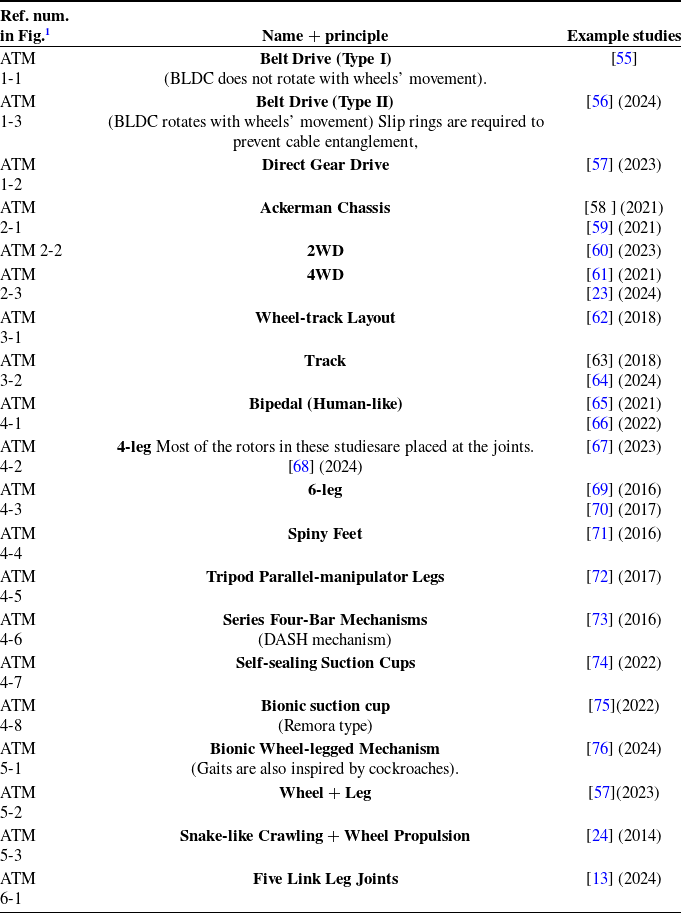
The design examples of ATM are listed in the following Table IV.
Mechanical design excerpt of aerial-terrestrial systems that use multi-driving system.

Table IV Long description
The table presents design examples of ATM, categorized by reference numbers, names, principles, and example studies. It includes various drive types such as Belt Drive, Direct Gear Drive, and Ackerman Chassis, along with different wheel and leg configurations like 2WD, 4WD, Track, Bipedal, 4-leg, 6-leg, Spiny Feet, Tripod Parallel-manipulator Legs, Series Four-Bar Mechanisms, Self-sealing Suction Cups, Bionic suction cup, Bionic Wheel-legged Mechanism, Wheel + Leg, Snake-like Crawling + Wheel Propulsion, and Five Link Leg Joints. Each entry is associated with specific studies and years, providing a comprehensive overview of mechanical design excerpts of aerial-terrestrial systems that use multi-driving systems.
1 ATM 1-X: Transmission Mechanism for Wheel Type.
ATM 2-X: Wheel Type Chassis.
ATM 3-X: Track.
ATM 4-X: Leg.
ATM 5-X: Mixture.
ATM 6-X: Chassis Lifting.
Corresponding figures are shown as follows:
3.2.1. Wheel
The multi-powered wheeled system primarily consists of multiple wheels.
Similar to the single-powered system, the multi-powered system also includes configurations with 2W, 3W, and 4W, as well as a special variable-wheel-count (VW) design.
Based on the previous studies [Reference Kossett, Purvey and Papanikolopoulos77, Reference Kossett, D’Sa, Purvey and Papanikolopoulos78, Reference Kossett and Papanikolopoulos79], the first design iteration involves a dual-wheel configuration combined with coaxial dual rotors to cancel out torque. The A-T mode transition involves disengaging the rotary drive shaft from the main transmission system in TM and controlling the claw-like clutch mechanism with servos during the AM. The second design iteration is similar to the first, with an improved supporting structure. The third iteration adds a tail rotor, transforming the design into a helicopter-like system with dual wheels.
The transition between AM and TM relies on two mechanisms: the supporting mechanism, where the robot is held up by “small tilt,” with similar principles but different specific designs. The wheel diameter is larger than the folded flight system, which helps protect the rotor system in TM. The folding blades enable compact storage, and the system is coupled with motors for deployment when needed.
The group later proposed a new design [Reference Morton and Papanikolopoulos80], which shares similarities with the previous designs but employs a quadrotor for AM and switches the frame extension mechanism to a screw + gear + four-bar linkage. The wheels no longer use long rod transmissions, instead placing motors directly at the wheel edges. A stabilizing bar was introduced. This likely reflects the group’s recognition of the complexity in previous designs.
Reference [Reference Zheng, Cai, Wang, Xu, Cao, Yu, Li, Meng and Lu81] introduces CapsuleBot, a dual-rotor system with a 2WD self-balancing vehicle. In TM, the servo-controlled wheels are powered by BLDC motors (with electrical slip rings to prevent wiring issues). The study proposes a new mechanism for the actuated wheel rotor: it uses a servo motor and a brushless motor to function as both a tilting rotor in the air and an actuated wheel on the ground, thus reusing the servo to control the wheel motion in TM while functioning as a rotor during AM. Detailed hardware diagrams are provided. The system is designed to produce low noise (ideal for reconnaissance missions).
Reference [Reference Cao, Xu, Yuan, Cao, Liu and Xie60] presents DoubleBee: a dual-rotor system with a rotating arm and a 2WD chassis (balance bike model), resembling a double-linked bamboo-copter design. This system includes dynamic modeling and supports four operation modes: AM, TM, and TSM, and decoupled mode (in which the robot’s pitch angle is changed by BLDC thrust rather than differential motor speed, allowing for “stooping” through low-height areas).
Reference [Reference Xu, Zheng, Wang and Liao13] describes a system where dual rotors with independent tilt and 2WD wheels with lifting capabilities are connected via a five-link mechanism (as shown in ATM 6-1 (Figure 15)) to improve adaptability and stability across different terrains. The multi-mode controller is included, with a detailed hardware BOM. The system operates in three modes: AM, TM, and TSM (to prevent tipping). In TM, the robot model is self-balancing.
Reference [Reference Zheng, Wang, Wu, Cai, Yu, Zhang, Tu, Meng, Lu and Gao36] introduces the Roller-Quadrotor, a three-wheeled design (one active wheel with rubber for enhanced friction and two passive wheels), coupled with a quadrotor and a motor for TM. In TM, the quadrotors primarily assist with steering. Compared to single-powered systems relying solely on rotors, this system has a longer operational time. It is modeled based on a planar unicycle motion model and a first-order inverted pendulum model, with necessary dynamic analysis provided. During TM operation, the quadrotor’s yaw motion propels the wheels forward, enhancing obstacle-crossing capabilities and propulsion. The A-T switching mechanism involves two BLDC motors that analogize the motion to that of a first-order inverted pendulum model. Steering is accomplished using the quadrotor’s roll motion.
Reference [Reference Fabris, Aucone and Mintchev18] presents a quadrotor with a variable soft-frame structure, which deforms through controlled collisions, featuring dual-stiffness properties (as shown in GD 1-6, Figure 3). The reset mechanism uses non-elastic wires, springs, and magnets for positioning (improving the frame’s stability in AM to prevent folding due to excess BLDC torque while allowing detachment during sudden collisions). The robot includes one active wheel and two passive wheels. The frame is designed to protect the propellers. This system is built on the synergies between a soft foldable frame, multimodal mobility, and autonomous navigation, using the Khadas VIM3 development board for data processing and advanced control tasks, along with various sensors, including an Intel T261 camera, a RADIX LI flight controller.
Reference [Reference Chang, Yu, Ji, Li, Yuan, Zhao, Ren and Zhan17] presents a similar design to ref. [Reference Morton and Papanikolopoulos80], but with a reversed umbrella-style quadrotor (controlled by linear servos and push-rod mechanisms for retracting or extending the frame), dual active wheels, and one passive stabilizing wheel. The system uses GAN-based NMPC (GAN-NMPC), with a detailed kinematic model, aimed at mitigating interference from strong winds.
Reference [Reference Zhiyu8] presents the Reconfigurable Land-Air Amphibious Robot (RLAAR), which uses motors (RoboMaster M2006) to drive the wheels and four-axis propellers for hybrid propulsion. The reconfiguration mechanism is based on servo-driven tilting. The study includes detailed dynamics analysis (based on the Kane method), kinematics analysis, and multi-body system analysis using Newton–Euler and Lagrangian methods. The wheel-wing structure features a coaxial design with the BLDC motors fixed at the end of the axle. The wheels are essentially gears along the axle’s midpoint, driven by motor gears. This design allows the wheels to remain stationary when not in use, which improves flight stability. The system uses backstepping control to design ground/air trajectory tracking controllers.
Reference [Reference Kalantari, Touma, Kim, Jitosho, Strickland, Lopez and Agha-Mohammadi55] introduces the Drivocopter, featuring a four-arm coaxial octocopter with four active wheels and a fixed tube-mounted wheel frame. The system uses GT3 2 MM belt drive (as shown in ATM 1-1, Figure 11) and includes detailed hardware flow diagrams. The robot is capable of autonomous navigation with Intel NUC processors, Velodyne Puck Lite radar (3D), Garmin radar (1D), and Realsense D435i cameras, controlled by a PIX 2.1 flight controller and a Teensy 3.2 ground controller. The system uses VIO and IMU to determine orientation and A* path planning for navigation.
Reference [Reference Wang, Zhang, Pan, Su and Li61] introduces an air-ground amphibious robot (AGAR) with a hybrid four-rotor system and 4WD chassis. The system includes dynamic analysis and PID control, discussing short-distance takeoff with 4WD at speed to avoid collisions.
Figure for the mechanical design excerpt of aerial-terrestrial systems that use multi-driving system (1/5).

Figure 11 Long description
The collage consists of five images. The first image shows a prototype of a spherical structure with labeled components such as gear and GT2 belt. The second image provides a top view of the relevant position of the spherical structure. The third image displays a prototype in wheel mode with labeled driving gear and wheel gear. The fourth image illustrates a comprehensive structural diagram of a multi-driving system with components like unified motor, active wheg, fixed wheg, rotor, timing belt, slip ring, and transform servo. The fifth image shows a prototype of a vehicle with a steering mechanism and a structure diagram of an Ackerman chassis with labeled steering servo, rear motor, and center of turning circle.
Reference [Reference Tan, Zhang, Liu, Jiao, Zhou and Li59] presents a six-rotor system with four wheels (Ackermann chassis with two-drive, two-steer wheels) using MPC control. The study focuses on dynamic analysis and improving algorithm stability during landing (resisting impact shifts).
Reference [Reference Jian82] features a quadrotor with four wheels (two active and two passive), comparing PID and backstepping control (with the latter showing better performance).
Reference [Reference Wang, Li, Chu and Qu83] introduces a quadrotor with a 4WD system designed for agricultural information collection using wide-angle lenses.
As shown in ATM 2-1 (Figure 11), Ref. [Reference Zhang, Guo, Ren, Zhu, Xu and Lu58] presents a quadrotor with an Ackermann chassis.
Reference [Reference Deng, Yang, Dong, Cui, Gao, Li and Tu23] explores a new decoupling method (as shown in GD 4-1, Figure 4) for UAV and UGV systems, allowing for air-ground docking and detachment via screw-like self-spinning motion, with BLDC torque or 4WD differential torque used for fastening. With the synergy of the UAV with a mobile landing platform, the BLDC differential torque or 4WD differential torque is used to provide the fastening force, allowing docking with an error of only 4 cm (thanks to the optimized connector guide surface design and spiral guide rails). After a 360-degree full connection, the UAV and UGV are in the same direction.
Reference [Reference Gao, Jin, Gao, Zhao, Zhu and Cai84] introduces a two-wheel-legged land-air locomotion robot (TLR) combining two-wheel-legged self-balancing robot (TSR) with stable cooperative algorithms and walking cooperative algorithms to enhance stability and load capacity. It features flight mode (quadrotor), dual-wheel mode (two active wheels), and four-wheel mode (two active wheels + 2 passive wheels with arm joint-based passive wheels). The crawling mechanism, a pantograph-shaped height-variable mechanism, is used to change the robot’s operating mode. The motors can tilt to provide forces along the X and Z axes in TM, enhancing stability. Detailed dynamics and kinematics analyses are provided.
3.2.2. Track
Reference [Reference Hu, Liang and Diao63] presents a design involving a quadrotor (with a foldable frame inspired by membrane-winged insects, which reportedly enhances maneuverability in low-speed regions during terrestrial mode) combined with a simple tracked chassis (powered by a pair of motors). The folding mechanism is a crank-slider design.
Reference [Reference Fan, Zhu, Zhang, Xu, Xu, Zhou, Zhang, Sun and Wen64] describes a quadrotor with outward-facing angled rotors paired with two active tracks (with the tracks wrapped around the frame and powered by motors on each side). The focus of this study is on Yaw stability and wind resistance. It includes kinematic analysis, an inflow model, and a simplified Dryden model. The study employs an adaptive stability augmentation (ASA) controller in conjunction with a standard cascade PID controller to improve performance.
3.2.3. Leg
Bipedal robots
As shown in ATM 4-1 (Figure 13(i)), Ref. [Reference Kim, Spieler, Lupu, Ramezani and Chung65] introduces the LEgs ONboARD drOne (LEONARDO, abbreviated as LEO), a design that integrates an inverted quadrotor with a bipedal robot. Each leg is equipped with three servos: one at the pelvis for lateral movement in the frontal plane and two at the front and rear of the hip for driving a parallel leg mechanism (as shown in Figure 3A in the original article). This robot employs synchronized control to distribute rotor thrust and leg movement, achieving remarkable balance (capable of skateboarding) and resilience against wind gusts up to 3.8 m/s. The study provides detailed dynamics and kinematics analysis, with hardware flow diagrams included. The TSM algorithm is activated by receiving data from foot sensors. The robot uses dual computers: a NanoPC-T4 (high-performance, running Robot Operating System (ROS2)) and a microcontroller (interfaces directly with the leg actuators, propeller motor controller, and inertial measurement unit (IMU), as well as collecting data from foot sensors). It can walk on slacklines and skateboards with assistance from the thrusters, although this increases power consumption (as noted in the original study). The algorithm design and mechanism analysis are quite detailed.
Based on the Jet HR1 [Reference Huang, Wang, Wei, Yu, Zhou, Lao, Huang, Zhang and Zhang85], Ref. [Reference Li, Zhou, Huang, Wang, Zhu, Wu, Zheng, Luo, Cao, Zhang and Huang66] presents the humanoid Jet-HR2, designed for search-and-rescue missions in hazardous terrain (cliffs, loose ground, and collapse-prone areas). As shown in ATM 4-1 (Figure 13 (ii)–(vi)), this system uses four ducted fans (two mounted at the waist and two placed under the feet), with a total of 10 joints. The study provides detailed hardware diagrams and discusses the distribution of the joints’ motors. It explores the stability of brief flight in conditions of low thrust-to-weight ratios (1.17), with experimental verification based on thrust vector control acting on the pitch axis.
4-LEG
As shown in ATM 4-2 (Figure 13 (iv)–(v)), Ref. [Reference Martynov, Darush, Fedoseev and Tsetserukou68] introduces MorphoGear, a system that uses six rotors and four legs (each leg powered by three Dynamixel MX-106 and MX-28 servos at the hip joints and MX-64 servos at the knee joints). This robot features a gripper at the foot. The legs can also serve as landing gear. The robot operates with three gaits (Trot Gait, Canter Gait, and Gallop Gait), providing precise placement accuracy (within centimeters) for straight-line and angular trajectory tracking (though straight-angle tracking has a total error of 20.7 cm). Videos of this system are provided for further clarification.
As shown in ATM 4-2 (Figure 13 (i)–(iii)), Ref. [Reference Zhao, Anzai and Nishio67] presents SPIDAR (SPherIcally Vectorable and Distributed Rotors Assisted Air-Ground Quadruped Robot), featuring distributed ducted fans. Compared to centralized motor systems (such as those in quadrotors or hexacopters), this layout is advantageous for handling variations in the center of mass of the operator. The rotors are equipped with spherically vectorable rotor apparatus [Reference Zhao, Anzai, Shi, Chen, Okada and Inaba86], and each leg provides four DOFs. The study includes detailed kinematic modeling due to the complexity of the system.
Reference [Reference Hu, Zhou, Gui, Zhai, Zhang and Dong87] features a quadrotor with a quaddrupedal dog design [Reference Hu88].
As shown in ATM 4-5 (Figure 14), Ref. [Reference Ceccarelli, Cafolla, Carbone, Russo, Cigola, Senatore, Gallozzi, Di Maccio, Ferrante, Bolici, Supino, Colella, Bianchi, Intrisano, Recinto, Micheli, Vistocco, Nuccio and Porcelli72] focuses on cultural heritage conservation, featuring a quadrotor and quadruped robot combination. The quadruped legs are based on a tripod (three-push-rod) mechanism [Reference Russo and Ceccarelli89].
Reference [Reference Ouyang, Chi, Lu, Wang and Ren90] presents the QQR (Quadruped-Quadrotor Robot), which integrates a quadrotor (CUAV Nora flight controller with TMOTOR F40 BLDC motors at the joints of the quadrupedal legs, allowing the robot’s configuration to change, such as into an X-H shape). The system uses a biorobotics-inspired central pattern generation controller for motion. Kinematic and aerodynamic models are created for body dynamics and flight dynamics. The study also explores a hierarchical coordination control scheme combining low-level locomotion control and high-level motion control. Reinforcement learning is employed to enhance walking capabilities and autonomously select the optimal movement mode (jogging or walking).
As shown in ATM 4-6 (Figure 14), Ref. [Reference Mulgaonkar, Araki, Koh, Guerrero-Bonilla, Aukes, Makineni, Tolley, Rus, Wood and Kumar73] introduces the “Flying Monkey,” a hybrid quadrotor and origami-style four-legged robot (each leg has two feet), which operates based on the DASH mechanism [Reference Birkmeyer, Peterson and Fearing91]. This system uses a single motor to drive folded laminate devices with numerous linkages, producing circular foot trajectories with a
 $180^\circ$
phase difference between the two feet on the same leg, enabling movement. The crawler has only one DOF (moving forward or backward), while steering is achieved through the yaw torque of the integrated quadrotor and compliance in the crawler’s joints. A small mechanical hand using an SMA actuator is included, capable of grasping objects weighing between 1 and 2 g and measuring 6 mm or less.
Reference [Reference Guo, Shen, Zhang and Zhang92] describes two prototypes: Type-A, with a quadrotor and quadruped legs (each leg has two DOFs), and Type-B, with a quadrotor and quadruped legs (each leg has three DOFs, using LX-15D servos). The study explores gait planning with a PID control. The kinematic model of the Type-B prototype’s crawling mode is established.
Hexapod (6-LEG)
As shown in ATM 4-3 (Figure 13 (iii)–(iv)), Ref. [Reference Pitonyak and Sahin70] presents a six-legged robot combined with a quadrotor, using inverse kinematics analysis. This system supports three gaits: tripod, wave, and ripple gait. The folding propellers are specifically chosen for their ability to fold between bifurcated femur segments and remain constrained while walking. The study also investigates unique motor mounting positions. An integrated IR transceiver is used at the motor base, with the IR light direction aligned with the motor axis, enabling the detection of wing position states (whether the wings are folded or extended). The design includes pockets on the legs to increase tibia arm stability during flight. Transition between modes is achieved by rotating the tibia servos by
 $270^\circ$
.
In the six-legged magnetic adhesion robot [Reference Kriengkomol, Kamiyama, Kojima, Horade, Mae and Arai93, Reference Ratsamee, Kriengkomol, Arai, Kamiyama, Mae, Kiyokawa, Mashita, Uranishi and Takemura69], a hexacopter is combined with an electromagnetic six-legged system, and each leg has three DOFs (as shown in ATM 4-3 (Figure 13 (i)–(ii))). The system applies vibration control methods applied through a vibrator installed at the first link to mitigate oscillation. The system employs PID flight control and LQG active vibration compensation.
Reference [Reference Liu, Wang, Sheng and Dong74] presents a quadrotor system combined with suction cups (as shown in ATM 4-7 (Figure 14), each side equipped with a pulley, with three suction cups on each pulley, all using a single pump). This gripper offers greater adaptability to attitude errors and tangential velocities compared to conventional suction cup grippers. Its primary function is to perch on a surface of a moving vehicle, thereby extending its range of motion and operational endurance. The gripper achieves a high success rate in attaching to objects with initial velocities (
 $\ge 1.07 \mathrm m/\mathrm s$
) or inclinations (up to
 $90^\circ$
). The working principle of the suction cup involves a trigger cup and a cup holder with side openings: when not in contact with an object, the trigger cup remains unaltered, tightly closing the cup holder’s opening. Upon contact with an object at an initial speed, the trigger cup deforms, breaking the seal with the cup holder, allowing air to flow through and be drawn out by the vacuum pump. The research includes complex mechanism design, detailed kinematic modeling, and trajectory analysis.
3.2.4. Mixture
Reference [Reference Sihite, Kalantari, Nemovi, Ramezani and Gharib57] introduces the M4 robot developed at Caltech, which utilizes 22 DOFs to enable six distinct motion forms (running, walking, crouching, quadrotor, tumbling, and dual-rotor assisted propulsion (MIP), as shown in ATM 5-2 (Figure 15)). Nonlinear collocation programming is used to compute control quantities in real time, allowing for thrust control. Without this, open-loop thrust calculations could lead to slippage. The wheel-wing design is similar to that of the RLAAR [Reference Zhiyu8], though the motors are positioned at the edges rather than the center (as shown in ATM 1-2, Figure 11).
Reference [Reference Sugihara, Zhao, Nishio, Makabe, Okada and Inaba94] presents a humanoid robot featuring three tiltable rotors (EDFs: electric ducted fans) for flight with vector control and a body equipped with footed legs that include passive wheels. The feet can be lifted to convert into wheel form, and the system uses BLDC-powered propulsion during wheeled mode. Three modes of operation are available: flight, walking, and running. The system is accompanied by detailed dynamics analysis, and a clutch mechanism, driven by a servo, locks the robot’s posture.
Figure for the mechanical design excerpt of aerial-terrestrial systems that use multi-driving system (2/5).

Figure 12 Long description
The image consists of multiple elements, including photos and diagrams, illustrating different mechanical designs for aerial-terrestrial systems. The top left section features a prototype of a rover with motors and wheels, labeled as ATM 2-2. The top right section shows a drone prototype with motors and propellers, labeled as ATM 2-3. The bottom section includes diagrams of different designs, such as servo-arm connections, link-bar mechanisms, and bio-inspired morphing mechanisms. Each design is labeled with specific identifiers like ATM 3-1 and ATM 3-2, and includes detailed views of mechanisms and prototypes. The diagrams highlight various components like wheels, tracks, driving wheels, and road wheels, with annotations explaining their functions. The image aims to compare and illustrate the mechanical designs and principles used in aerial-terrestrial systems.
Reference [Reference Mintchev and Floreano62] describes a robot with an H-shaped frame, incorporating a quadrotor for flight, dual wheels, and dual-side tracks that work in synchrony (as shown in ATM 3-1, Figure 12). This design may enhance terrain passability, although the effectiveness of the narrow tracks may not provide enough grip. The standout feature is the foldable arm mechanism, actuated by a screw to enable
 $180^\circ$
rotation, allowing the robot to recover from a rollover or perform a flip.
As shown in ATM 5-1 (Figure 15), Ref. [Reference Qin, Xu, He, Qi, Zheng, Hu, Cheng, Zuo, Zhang and Ji76] presents an air-land amphibious inspection drone (AAID) inspired by cockroach-like half-wheel-foot (6W) chassis combined with a quadrotor. The system includes dynamic analysis and uses infrared optoelectronic sensors for obstacle detection, enabling autonomous AM–TM mode switching. The system is compared using LQ, cascade PID, and fuzzy PID controllers, with the former demonstrating the best performance in this setup.
As shown in ATM 5-3 (Figure 15), Ref. [Reference Latscha, Kofron, Stroffolino, Davis, Merritt, Piccoli and Yim24] introduces the Hybrid Exploration Robot for Air and Land Deployment (H.E.R.A.L.D), which combines a quadrotor with two parallel serpentine multi-functional chassis featuring three active wheels (two on the ends and one in the middle). The chassis is capable of four DOFs and can fold for crawling functionality. The air-ground platform can dock using a matrix of passive magnets (alternating pairs of six magnets) [Reference Yim, Shirmohammadi, Sastra, Park, Dugan and Taylor95].
Figure for the mechanical design excerpt of aerial-terrestrial systems that use multi-driving system (3/5).

Figure 13 Long description
The image features a collage of various photos and diagrams illustrating the mechanical design of aerial-terrestrial systems that utilize multi-driving systems. The first row includes prototypes and diagrams of different components such as propellers, arms, and legs, highlighting their mechanical structures and functions. The second row shows additional prototypes and diagrams, focusing on the mechanical structure and different modes of operation. The third row presents exploded views and motion demonstrations of the systems, detailing the mechanical design and functionality. Each element in the collage is labeled with specific parts and their roles, providing a comprehensive overview of the mechanical design principles.
Figure for the mechanical design excerpt of aerial-terrestrial systems that use multi-driving system (4/5).

Figure 14 Long description
The image contains a table and multiple diagrams. The table lists various mechanical designs for aerial-terrestrial systems, each with a reference number, name, principle, and example studies. The diagrams illustrate different designs such as direct servo-BLDC connection, servo-arm connection, servo-driven link-bar mechanism, bio-inspired morphing mechanism, pushrod-driven umbrella linkage, dual-stiffness arm mechanism, servo-driven variable-pitch propellers, bidirectional motors/ESCs, spokeless wheel, propeller-wheel integrated design, binding mechanism, and magnet mechanisms. Each diagram shows the structure and function of the respective design, highlighting components like servos, BLDCs, springs, magnets, and propellers. The designs are categorized into four groups: frame reconfiguration mechanism, thrust vector control, ground movement, aerial-terrestrial coupling, and docking module.
Figure for the mechanical design excerpt of aerial-terrestrial systems that use multi-driving system (5/5).

Figure 15 Long description
The image consists of multiple elements, including photos, diagrams, and illustrations, showcasing the mechanical design of aerial-terrestrial systems that use multi-driving mechanisms. The first section features a prototype of a robotic system alongside a 3D stereo view and a 2D side view model demonstration. The second section illustrates cartoon depictions of the system's transformation into different modes, such as crouching, tumbling, walking, and flying. The third section displays another prototype with a detailed CAD model of the MK II leg, highlighting components like the wheel with motor, 2-Degree of Freedom servo mechanism, and docking plate. The final section shows a prototype of a system with a parallel leg structure, including a 3D view and a side view model diagram that labels different links and joints. The images are overlaid and side-by-side, providing a comprehensive view of the system's design and functionality.
As shown in ATM 1-3, Figure 11, Ref. [Reference Shi, Jiang, Ma, Qi and Jin56] discusses the MTABot, featuring a balanced tail, dual rotors, and a multifunctional wheel-leg appendage system. The robot operates in three modes: rolling, crawling, and flying. The wheel radius, sector angle, and wheel axis offset relative to the body center of gravity (BCoG) are optimized to improve climbing ability and land–air maneuverability. The appendage structure includes a unified motor that drives the wheels using a timing belt and a BLDC vector control system – owered via an electrical slip ring. The transform motor is responsible for mode switching between flying, walking, and wheeled modes. The BLDC motor and servo are both connected to the wheels and are powered through electrical slip rings, which prevent wire entanglement during mode transitions.
As shown in ATM 4-4 (Figure 13), Ref. [Reference Pope, Kimes, Jiang, Hawkes, Estrada, Kerst, Roderick, Han, Christensen and Cutkosky71] introduces the Stanford Climbing and Aerial Maneuvering Platform (SCAMP), a micro-aerial vehicle (MAV) that integrates a quadrotor with 2-DOF spiny feet capable of gripping rough surfaces. The feet are actuated by two servos: the Hitec HS-5035HD servo controls the up-and-down extension and the Hobbyking HK-5,320 servo handles rotation and in-out motion (as shown in Figure 2 of the original paper). The robot also features two passive wheels mounted at the rear, enabling perching capabilities. The research focuses on allowing the robot to reattach after a failed step, energy consumption, and stability algorithms. The climbing mechanism is mounted on the top to prevent vibrations during contact with vertical surfaces that might cause detachment, ensuring a successful reattachment. The robot uses ground-effect suction to enhance wall adhesion, and the vertical acceleration threshold (0.8 g in less than 100 ms) is used to determine successful attachment. The study emphasizes the process of wall climbing and detaching from the wall using a takeoff rod and quadrotor ground-effect assistance. Videos of the robot can be accessed for a clearer understanding [96].
4. Aerial-aquatic
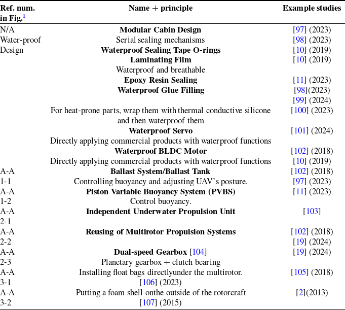
In comparison to A-T systems, the aerial-amphibious (A-A) systems face greater design challenges due to the differing mediums [Reference Bai, Jin, Liu, Zeng and Lian11]. Typically, two separate power systems are required for two different mediums. However, recent research has explored the reuse of quadrotor systems, enabling the use of a single power source for both aerial and underwater modes. Since the research in this domain is relatively scarce, this section includes studies focused on both aquatic and surface mediums (with the underwater medium presenting more design challenges).
Comparison of these systems are presented in the Table V.
Mechanical design excerpt of aerial-aquatic systems (A-A).

Table V Long description
The table presents a comparison of different waterproof design principles and their corresponding example studies in aerial-aquatic systems. It includes columns for reference numbers, names and principles, and example studies. The table lists various waterproofing techniques such as modular cabin design, serial sealing mechanisms, waterproof sealing tape O-rings, laminating film, epoxy resin sealing, and waterproof glue filling. It also mentions specific components like waterproof servo, waterproof BLDC motor, ballast system, piston variable buoyancy system, independent underwater propulsion unit, reusing of multirotor propulsion systems, dual-speed gearbox, and float bags. Each design principle is associated with specific studies and years, providing a comprehensive overview of advancements in waterproofing technologies for aerial-aquatic applications.
1 A-A 1-X: Buoyancy Control.
A-A 2-X: Underwater Propulsion.
A-A 3-X: Passive Floating Mechanism.
The corresponding figures are shown as follows.
Figure for the mechanical design excerpt of aerial-aquatic systems (1/2).

Figure 16 Long description
The image consists of three elements: a photo, a diagram, and an illustration. The photo on the left shows a prototype of an aerial-aquatic system with a water ballast system. The diagram in the middle provides a side view of the ballast system, highlighting components such as the water cylinder, water pump, two-way valve, and piston. The illustration on the right depicts the process diagram of the mechanisms in three stages: expanded, transforming, and folded. The combined visual meaning illustrates the mechanical design and functionality of the aerial-aquatic system, focusing on the foldable and self-deployable arm mechanism.
For underwater operations (with depths greater than 20 cm), communication challenges arise [Reference Liu, Wang, Tang, Qin, Zhang, Yang and Zou99], especially with common control bands like 2.4/5G [Reference Zhu, Guo, Li and Wang10]. Suggested solutions include adding a mode recognition system for autonomous underwater control and a low-frequency communication system, which accepts only critical instructions, storing exploration data on cards.
4.1. Single-driving system
In terms of biomimetic design, wings are designed to fold when submerged in water (similar to an osprey), reducing the drag during entry. The wings can also adjust their angle in the air to change flight dynamics [Reference Liu, Wang, Tang, Qin, Zhang, Yang and Zou99]. The system utilizes a tri-rotor (with one rotor at the front and two at the rear) and a dual-propeller fixed wing (with two BLDC motors) combined with a submersible underwater vehicle (which operates without a water tank). The single-drived system relies on PID control. Detailed dynamic analyses are conducted, addressing the relationship between the body parameters and buoyancy in both water and air, laying the groundwork for flight and diving controls.
The Nezha series of amphibious aerial vehicles developed by the Zheng Zeng team at Shanghai Jiao Tong University deserves attention. This research continues to focus on this direction [Reference Bai, Jin, Liu, Zeng and Lian11], involving a quadrotor combined with a piston-variable buoyancy system (PVBS, as shown in A-A 1-2, Figure 16) for ocean monitoring. As shown in GD 1-5 (Figure 3) the system uses a crank-slider structure [Reference Bai, Wang, Chen, Zheng, Xin, Deng and Sun108] to operate the buoyancy system, along with a torsion spring to aid in the extension and retraction of the quadrotor during submersion and flotation. When submerging, the push rod retracts, expelling air and folding the rotors. During flotation, the push rod extends, inflating, and the rotors are deployed. The reuse of components minimizes operational delays, with a system framework diagram included. This design uses PID control for both aerial and aquatic modes, and post-fitting mapping is applied to linearize the linear actuator in nonlinear situations (such as changes in water depth affecting the performance of the acturators).
Reference [Reference Wang and Hui97] introduces ABDragon (named after the Chinese toy ”Bamboo-copter”), which operates in three modes: underwater submersion, passive water-surface floating, and flight. The vehicle utilizes coaxial motors and a VBS system consisting of a water-drawdown tank resembling a submarine.
Figure for the mechanical design excerpt of aerial-aquatic systems (2/2).

Figure 17 Long description
The table presents various mechanical design excerpts for aerial-aquatic systems, categorized into different general designs (GD). Each row lists a design type, its principle, and example studies. The designs include Direct Servo-BLDC Connection, Servo-Arm Connection, Servo-driven Link-bar Mechanism, Bio-inspired Morphing Mechanism, Pushrod-driven Umbrella Linkage, Dual-stiffness Arm Mechanism, Servo-driven Variable-pitch Propellers, Bidirectional Motors/ESCs, Spokeless Wheel, Propeller-Wheel Integrated Design, Binding Mechanism, and Magnet. Each design is illustrated with specific examples and references to studies. The table also categorizes the designs into Frame Reconfiguration Mechanism, Thrust Vector Control, Ground Movement, Aerial-terrestrial Coupling, and Docking Module.
Reference [Reference Cacace, Lippiello, Paduano and Pierro106] presents the PlaCE Project, which incorporates a hexacopter with a passive buoyancy system (a large buoyancy chamber in the center and six buoyant cones below the motors, as shown in A-A 3-1(Figure 17)). This system is designed for ocean data collection and offshore monitoring. The vehicle is capable of autonomous operation via a high-performance onboard computer or manual control, and carries multispectral optical detection equipment.
Reference [Reference Esakki, Mathiyazhagan, Moses, Rao and Ganesan12] describes a quadrotor system that integrates an algae collection device. The design includes structural analysis and Finite Element Analysis (FEA)-based optimization to reduce weight.
Reference [Reference Alzu’bi, Mansour and Rawashdeh102] discusses the Loon Copter, which operates in three modes: flight, water surface, and underwater. The quadrotor system (with waterproof BLDC motors) addresses the challenges of reusing airborne propulsion systems (as shown in A-A 2-1 (Figure 16)) underwater, such as cavitation damage at high speeds. Through underwater thrust experiments, optimal rotational speeds (around 800 RPM) are determined. The system also includes a VBS (as shown in A-A 1-1 (Figure 16), The cylinder contains a water pump and a water tank. The water in the tank is isolated from the air in the cylinder by a piston.) that enables the vehicle to tilt
 $90^\circ$
when submerged, turning into an underwater propulsion mode. This design uses the Multiwii Pro flight controller (ATmega 2560) and Futaba 72 MHz for underwater communication. The vehicle weighs 2.7 kg and employs PD control for aerial mode and open-loop control for underwater mode.
Reference [Reference Rao, Xie, Yang, Xu, Lv, Zheng, Deng and Guo100] introduces a coaxial octocopter with tiltable arms (with two arms independently rotating), addressing stability concerns when tilting the rotors. The system uses PID-based attitude control and transition control, with preliminary experiments validating its performance. Kinematic models for both aerial and underwater modes are also established.
Reference [Reference Tan, Liang, Su, Qin, Li and Huo98] describes a hexacopter system primarily focused on stability control algorithms, comparing PID, sliding mode control (SMC), and active disturbance rejection control (ADRC). The study includes dynamic and kinematic modeling and features waterproof compartments and seals.
Reference [Reference Liu, Dou, Yan, Huang, Gao, Wang, Cui, Ren, Dou, Gao, Chen and Chen19] discusses the TJ-FlyingFish, a quadrotor system with a dual-speed planetary gearbox [Reference Tan, Siddall and Kovac104] and neutral buoyancy design. As shown in A-A 2-3 (Figure 17), the key mechanism in the planetary gearbox is the two clutch bearings / one-way clutchs which are connected in reverse series (working principle: In a locking state, the sleeve will tend to move with the shaft due to the friction. If the shaft force is large enough, the sleeve will move with the shaft (in the same movement direction.), cooperating with BLDCs which are capable of bidirectional rotation, each rotating direction can correspond to a thrust output system. This design can maintain rotational speed in aerial mode and increase torque in aquatic mode. Besides, the study also explores cross-medium positioning based on multi-sensors. The study investigates aerial-water mode switching (with specific motor actions required) and an independent propulsion vectoring mechanism for improved aquatic agility in yaw and horizontal movement. However, autonomous underwater navigation performance is noted to be suboptimal due to the vehicle’s non-streamlined shape and motor configuration, as well as the lack of an underwater movement model.
4.2. Multi-driving system
The Nezha series also includes [Reference Bi, Jin, Lyu, Zeng and Lian109], which presents the Nezha-mini, a miniature hybrid aerial-underwater vehicle (HAUV) with a modal transition strategy. The vehicle is equipped with an X-shaped quadrotor and three underwater propellers (one at the bow for vertical lift and two at the stern for forward motion and differential steering). This layout was analyzed through fluid dynamics modeling and has been shown to be more efficient than a alternative configuration (two-bow, one-stern propeller), which may fail to submerge effectively. The system also includes dynamic modeling, along with a basic introduction to its control strategy.
The research team behind refs. [Reference Bai, Jin, Liu, Zeng and Lian11] and [Reference Bi, Jin, Lyu, Zeng and Lian109] also proposed the Nezha-B, a compact system with a 124 mm diameter. As shown in A-A 2-1 (Figure 16), it features an interesting streamlined shell design, with misaligned upper and lower quadrotor motors (to reduce volume and balance torque), along with an underwater propulsion system (one Z-axis propeller at the front and two X-axis propellers at the rear, similar to the configuration in ref. [Reference Bi, Jin, Lyu, Zeng and Lian109]). The system has separate control systems for both aerial and underwater modes. This prototype has no isolation chamber because all components are directly installed after waterproofing treatment. The study includes both aerial and underwater dynamic analysis, with PID control. The experiments conducted are comprehensive.
Reference [Reference Li, Wang, Zhang, Song, Wang, Tan, Zhao, Wang, Sun, Yang, Liu, Chen, Xu, Nguyen, Kovac and Wen75] draws inspiration from the remora (Echeneis naucrates), known for its adhesion redundancy, where it can adhere to a surface even with only 1/2 or 1/3 of its suction disk in contact. Using micro-computed tomography (micro-CT), the researchers investigated the morphological features that enable partial adhesion of the disk. These researchers’ previous studies [Reference Wang, Yang, Chen, Wainwright, Kenaley, Gong, Liu, Liu, Guan, Wang, Weaver, Wood and Wen110] indicated that the soft lip of the disk acts as a seal and that the rotatable lamellae, covered in sharp spinules, enhance friction. As shown in ATM 4-8 (Figure 14), The principle of the bionic suction cup: multiple lamellae are controlled by a microfluidic driver and form a lever mechanism with an elastic stainless steel sheet. When the driver sucks liquid, the lamellae compress the volume of the chamber, increasing the corresponding chamber pressure while increasing the area of the lamellae contacting the target object (clever thin sheet mechanism design). At the same time, the chamber pressure acts on the lamellae, making them stick closer to the target surface. This is a very clever design. However, just as the gecko-like suction cup needs an initial velocity to attach to the target object, the remora-like suction cup also needs to be impacted by a certain initial velocity before it can attach to the target object. The study also explores the relationship between the number of lamellae and suction force, concluding that more lamellae increases suction. The three-blade folding propeller (based on Gemfan 5-inch blades) compared to commercial propellers shows about 19% shorter detachment time from the water surface. It is passively folded underwater and deployed in the air after sufficient torque is applied by the BLDC motors. This propeller provides both swimming power in the water and lift in the air.
Reference [Reference Esakki, Ganesan, Mathiyazhagan, Ramasubramanian, Gnanasekaran, Son, Park and Choi105] focuses on water quality monitoring. The theoretical model uses a coaxial octocopter (one arm with four BLDC motors and a servo for rotation to serve as a surface propeller), while the practical model features a quadrotor with each BLDC motor connected to an individual servo.
5. Triphibious
The term “triphibious” refers to vehicles that offer superior environmental adaptability [Reference Zhong, Cao, Chai and Bai7]. Research in this mode is scarce, so a detailed description is provided. Key highlights from previous studies have already been listed in the table. The four multi-environment robots are shown in Figure 18.
Triphibious systems.

Figure 18 Long description
The image contains multiple photos and diagrams illustrating triphibious systems in different operational modes. The first row shows a quadrotor in aerial mode, a boat in aquatic mode, and a mono-wheel on land. The second row features a prototype and its transformations into aerial, terrestrial, and aquatic modes. The third row displays another prototype in aerial, aquatic, and terrestrial modes, with a note on replaceable wheel designs. The fourth row includes a system in aerial and terrestrial modes, and another in aquatic and terrestrial modes with wheels. Each image highlights the versatility and adaptability of the triphibious systems across different environments.
5.1. Single-driving system
As shown in TRI 1-1 (Figure 18), Ref. [Reference Kawasaki, Zhao, Okada and Inaba2] introduces MUWA (Multi-field Universal Wheel for Air-Land Vehicle), designed for disaster rescue operations and equipped with 3D measurement capabilities (xtion and onboard cameras). This system combines a quadrotor with a water-surface floating shell (as shown in A-A 3-2 (Figure 17), a ring-shaped shell made from polystyrene foam), which can be reused as a single-wheel for TM. It employs variable-pitch propellers (as shown in GD 1-7, Figure 3), which are controlled by a servo mechanism (rotating pair-moving pair-rotating pair), are key to normal operation in terrestrial mode. Because changing the propeller angle alters the direction of thrust. The vehicle can transition to a single-wheel mode by applying lift to raise the vehicle. A special motion modes, the Tornado Motion, are also introduced. The paper provides dynamic and kinematic analysis.
As shown in TRI 1-2 (Figure 18), Ref. [Reference Zhu, Guo, Li and Wang10] describes a tumbleweed-like system with a cylindrical wind tumbleweed design. The system features a coaxial octocopter, equiped with waterproof BLDC JFEC U2216 KV2400 motors. Two communication units, NRF24L01 for signal transmission and Futaba FM72 MHz for manual control (up to 3 m underwater), are used.
Reference [Reference Takahashi, Yamashita, Sato, Kutsuna and Yamada107] essentially adopts the wind tumbleweed system, where passive wheels of different shapes (spherical, round, or made from lightweight materials such as foam board for sufficient buoyancy, as shown in TRI 1-3 (Figure 18),) are swapped to achieve different functions. The article uses an Linear Quadratic Regulator (LQR)-based adaptive-feedback controller to achieve trajectory tracking in uncertain inertial conditions caused by wheel changes. Detailed dynamic analysis and algorithm design are also provided. The study also introduces a new charging device that simplifies the complex issue of automatic drone charging by converting it from a three-dimensional (precise landing) to a two-dimensional (direct backing into a charging dock) problem. This research shows that developing a triphibious vehicle is not as challenging as it might seem.
5.2. Multi-driving system
As shown in TRI 1-4 (Figure 18), Ref. [Reference Zhong, Cao, Chai and Bai7] presents the TR-TRS (a triphibious robot with a tilting-rotor structure), which combines flight, walking, small windmills/wind tumbleweed (with passive wheels and reused BLDC motors by using tilting servos), and water-surface propulsion. The passive wheels are equipped with brake pads, which can be retracted into the thighs. The calves are equipped with push rods that affect the position of the brake pads. The legs are rotated by a servo to switch between the small windmill and leg/windmill configurations.
6. Overall construction of the MDMs and designing suggestions
This section provides a concise overview of the practical implementations commonly adopted in existing MDM systems. A general overview of the hardware architecture commonly adopted in MDMs is presented in Figure 19.
Overall hardware configuratoins of MDMs.

Figure 19 Long description
The diagram illustrates the on-vehicle components for a multi-domain system. It includes several key sections: RF Communication, Control Unit, Power Supply, Propulsion System, IMU, and Mission Specific Optional Module. The RF Communication section features a 2.4GHz UHF and 72MHz VHF system connected to a host or operator via a remote controller and laptop. The Control Unit section includes an ordinary flight control system and a high-performance mini PC, interfacing with the IMU and mission-specific modules through PC, UART, or SPI connections. The Power Supply section comprises a PMU/BEC and a battery, providing power to various components. The Propulsion System includes an ESC and motor, driven by PWM signals. The IMU and Mission Specific Optional Module section features various sensors and devices like cameras, GPS, LIDAR, optical flow, strength evaluation, and ultrasonic sensors. The diagram shows the interconnectedness and flow of signals and power between these components, highlighting the integration of different systems for the operation of the multi-domain vehicle.
6.1. Hardware
6.1.1. Control system
Flight controllers such as Pixhawk (the most prevalent in hardware-focused studies) or just 32-bit microcontrollers (e.g., STM32) are typically employed. For basic flight operations, 8-bit microcontrollers like Arduino Mega are sufficient. More demanding applications – such as onboard image processing or robotic arm manipulation – often utilize a dual-MCU architecture: one dedicated to flight control and the other to high-speed computation.
6.1.2. Propulsion system and operators
Servo motors are widely used in legged locomotion (e.g., DYNAMIXEL servos with angle feedback), BLDC thrust vectoring (e.g., standard servos such as RDS3218), wheel-driven propulsion (high-speed servos), and crawling mechanisms. The selection of BLDC motors is determined by thrust requirements and mission profiles.
6.1.3. Communication
The majority of systems employ 2.4 GHz or 5 GHz communication modules. For extended range or underwater operations, lower-frequency alternatives (e.g., 72 MHz) are adopted.
6.1.4. Environment sensing
Sensor suites are tailored to specific applications. Vision-based or computationally intensive tasks often incorporate high-performance embedded computers (e.g., NVIDIA Jetson) paired with stereo cameras (e.g., Intel RealSense). LiDAR is commonly used for simultaneous localization and mapping (SLAM) and obstacle avoidance. Optical flow sensors measure relative displacement, while ultrasonic sensors provide distance measurements. Domain-specific sensors (e.g., for water quality, radiation, or structural integrity monitoring) may also be integrated.
6.1.5. Mechanical structure
Frames are typically custom-fabricated from carbon fiber, with non-load-bearing components often 3D-printed.
6.2. Software and alghorihm
6.2.1. Mechantronic design
Most systems use SolidWorks and its built-in toolbox for development and simulation [Reference Gefen and Zarrouk15], with CATIA [Reference Esakki, Mathiyazhagan, Moses, Rao and Ganesan12] or Ansys [Reference Esakki, Mathiyazhagan, Moses, Rao and Ganesan12, Reference Esakki, Ganesan, Mathiyazhagan, Ramasubramanian, Gnanasekaran, Son, Park and Choi105], or Adams for FEA simulation. Some use UG simulations [Reference Guo, Shen, Zhang and Zhang92], with Mujoco for mechanical simulations. PCB designs are made using Altium Designer or KiCad, depending on the project requirements, with no restrictions.
6.2.2. Algorithms
PID controllers are most common, though LQR, MPC, and LQG are also applied [Reference Ratsamee, Kriengkomol, Arai, Kamiyama, Mae, Kiyokawa, Mashita, Uranishi and Takemura69]. Algorithms are frequently simulated in MATLAB [Reference Xian, Zhao, Zhang and Zhang111]. Ardupilot is widely used for ground control and firmware, with ROS often deployed on higher-performance onboard computers.
7. Discussion
7.1. Limitations and challenges
For all systems, it is essential to consider the smooth transition between modes.
7.1.1. Aerial-terrestrial systems
Whether using single- or multi-powered systems, many designs leverage the ground effect of multirotors [Reference Matus-Vargas, Rodriguez-Gomez and Martinez-Carranza112] to enhance obstacle traversal and reduce friction [Reference Gao, Jin, Gao, Zhao, Zhu and Cai84]. However, while the ground effect can be advantageous, it also introduces disturbances to the drone’s stability. The presence of turbulent airflow around the rotors can lead to variations in lift and drag, which directly impact motion control precision [Reference Zheng, Wang, Wu, Cai, Yu, Zhang, Tu, Meng, Lu and Gao36].
For optimal performance, a simple structure is preferable. Overuse of folding mechanisms increases nonlinearity, making control more difficult [Reference Zheng, Wang, Wu, Cai, Yu, Zhang, Tu, Meng, Lu and Gao36], and complex mechanisms are harder to implement in practical scenarios.
There is a balance in choosing the optimal size [Reference Kossett and Papanikolopoulos79], as larger robots provide better endurance and payload capacity, while smaller robots offer lower cost and superior maneuverability in narrow terrains.
The structural integrity and collision resilience of wind tumbleweed designs can be relatively weak [Reference Yamada, Nakao, Hada and Sawasaki21]. Also, wind tumbleweeds may struggle with rugged terrain [Reference Shi, Jiang, Ma, Qi and Jin56]. Integrating interesting shell designs (such as those using universal joints) [Reference Briod, Kornatowski, Zufferey and Floreano113] into the wind tumbleweed design may enhance its structural integrity. Besides, direct coupling can also reduce stability because any collision-induced disturbances or vibrations affect the quadrotor’s attitude, making trajectory tracking and adjustments difficult. Hence, adding a universal joint can mitigate these issues, as the cage may rotate compliantly in response to obstacles, leaving the multirotor unaffected. The addition of a universal joint makes the system more complex, requiring more intricate force and control analysis. Whether or not to add a universal joint depends on the specific design requirements. Alternatively, a cage with non-hub wheels can be used [Reference Yamada, Nakao, Hada and Sawasaki21].
Single-driving systems: Despite the simplicity of the design, single-powered systems need to prioritize stability. In aerial-terrestrial systems, if one submodule of the propulsion system fails, it can cause the entire system to fail, thus impacting the execution of tasks [Reference Deng, Yang, Dong, Cui, Gao, Li and Tu23].
For wind tumbleweed systems with partial wheeled components, the yaw angle control is performed while compensating for large friction forces. As a result, the control performance deteriorates under low thrust conditions [Reference Pan, Jiang, Zhang, Xu and Gao32]. Also, for the wind tumbleweeds, control remains a significant challenge. Due to their larger size [Reference Pimentel and Basiri39], their shell can negatively affect aerodynamic performance [Reference Yamada, Nakao, Hada and Sawasaki21].
Coupling aerial and terrestrial modes for optimization is difficult [Reference Zheng, Cai, Wang, Xu, Cao, Yu, Li, Meng and Lu81], and the large external shell and rotor operations can lead to dust disturbance [Reference Kalantari, Touma, Kim, Jitosho, Strickland, Lopez and Agha-Mohammadi55], which is detrimental to image detection [Reference Dias and Basiri14]. Dust disturbance can be dangerous in certain specialized inspection scenarios.
Multi-driving System These systems involve complex mechanisms, requiring extensive dynamic modeling and analysis [Reference Zhiyu8]. In these systems, the more functions they incorporate, the more components are needed, leading to an increase in weight [Reference Jia, Bai, Ding, Shu, Deng, Khoo and Chirarattananon51]. This weight increase affects performance in other modes, especially flight mode, where endurance and maneuverability can be compromised [Reference Sihite, Kalantari, Nemovi, Ramezani and Gharib57]. Overly intricate designs lead to highly complex structures, and the integration of hardware and experimental validation is often prone to failure, making development extremely challenging, as evidenced by the nearly three-year-long research span from [Reference Kossett and Papanikolopoulos79].
For bipedal systems, achieving the robustness and stability similar to human motion remains a significant challenge [Reference Kim, Spieler, Lupu, Ramezani and Chung65]. Control is also difficult, and stability is distinct from that of quadrupeds [Reference Guo, Shen, Zhang and Zhang92].
For quadruped and hexapod systems, the increased number of devices results in higher energy consumption and greater weight.
7.1.2. Aerial-aquatic system
Operating across two media with vastly different properties – such as density, drag, and structural requirements – poses considerable challenges for the design of propulsion systems in aerial-aquatic robots. These constraints often lead to compromised performance compared to dedicated UAVs or unmanned underwater vehicles (UUVs) operating in their native environments [Reference Bi, Jin, Lyu, Zeng and Lian109]. For instance, waterproofing and pressure resistance requirements increase overall weight and volume, adversely impacting aerial agility and endurance. Designers must therefore make deliberate trade-offs to balance performance in both domains.
For diving-capable multimodal systems, special attention must be given to attitude stabilization and power management during water exit, since wave-induced perturbations may introduce significant body oscillations [Reference Bi, Jin, Lyu, Zeng and Lian109].
From a mechatronic standpoint, employing multiple dedicated transmission systems for different media generally results in reduced energy efficiency [Reference Bai, Jin, Liu, Zeng and Lian11]. Thus, designs that maximize component reuse across operational modes are often preferred. Additionally, a streamlined design is essential to minimize drag during both aerial and aquatic locomotion, as highlighted in Ref. [Reference Bi, Xu, Shen, Zeng and Lian103].
Communication presents another significant challenge in underwater operations. Systems often employ acoustic modems for subsea communication or utilize predefined commands acquired at the surface before submerging [Reference Bi, Jin, Lyu, Zeng and Lian109]. Alternatively, some platforms integrate depth sensors with autonomous scheduling to periodically surface for communication.
Furthermore, control systems must account for substantial nonlinearities introduced during cross-domain transitions, and robust waterproofing is critical for all electronic and actuation components. Mode transition – particularly water-to-air emergence – represents a major research focus, as evidenced in refs. [Reference Li, Wang, Zhang, Song, Wang, Tan, Zhao, Wang, Sun, Yang, Liu, Chen, Xu, Nguyen, Kovac and Wen75] and [Reference Bi, Xu, Shen, Zeng and Lian103].
7.2. Application and prospect
Representative application scenarios of MDMs are summarised in Figure 20.
7.2.1. Application
Disaster response and rescue
In disaster scenarios, the environment is often highly complex, with a large amount of uneven terrain that hinders the deployment of unmanned ground vehicles (UGVs). Narrow spaces, as well as numerous hazards that can cause UAVs to fail, make the deployment of UAVs particularly difficult [Reference Salaan, Tadakuma, Okada, Sakai, Ohno and Tadokoro29]. In seismic events [Reference Hu, Liang and Diao63], researchers in earthquake-prone areas have made significant contributions to MDMs. UAVs alone face challenges in direct contact with target objects, as maintaining stable contact in flight requires highly precise algorithms and the addition of robotic arms. In contrast, hybrid aerial-terrestrial UAVs are advantageous in this regard [Reference Salaan, Tadakuma, Okada, Sakai, Ohno and Tadokoro29, Reference Premachandra, Otsuka, Gohara, Ninomiya and Kato33]. Some MDMs can even deform to navigate through extremely narrow spaces [Reference Fabris, Aucone and Mintchev18, Reference Latscha, Kofron, Stroffolino, Davis, Merritt, Piccoli and Yim24].
Application.

Figure 20 Long description
The image contains six separate photos showcasing drones used in various applications. The first image shows a drone on a floating platform in water, labeled as Environment Protection. The second image depicts a drone inspecting a concrete wall, labeled as Industrial Detection. The third image features a drone carrying a package, labeled as Delivery/Logistic. The fourth image includes a diagram of a drone flying towards a target building, labeled as Military. The fifth image shows a drone launching a missile, labeled as Mine Clearance. The sixth image presents a diagram of drones navigating around a building, labeled as Rescue.
For disaster response, particularly in the context of fires or hurricanes, UAVs are essential tools for rapid deployment and assessment in otherwise inaccessible environments. Hybrid systems equipped with a combination of aerial and terrestrial functionalities offer an ideal solution for accessing challenging environments and facilitating rescue operations.
Military applications
Recent conflicts such as the Russo-Ukrainian War, tensions between the Democratic Republic of the Congo and Rwanda, and the Israel–Hamas war have underscored the growing importance of UAVs in modern warfare. UAVs play critical roles in tasks ranging from artillery calibration and reconnaissance to direct combat applications involving armed drones [Reference Zheng, Cai, Wang, Xu, Cao, Yu, Li, Meng and Lu81]. The strategic use of hybrid systems for stealthy search missions and intelligence gathering benefits from their low-noise profiles and multi-terrain capabilities [Reference Jian82, Reference Fan, Zhu, Zhang, Xu, Xu, Zhou, Zhang, Sun and Wen64].
While military drones are often used for offensive purposes, there is a growing potential for using these versatile MDMs for post-conflict search-and-rescue missions. In hazardous environments, such as those contaminated with unexploded ordnance, UAVs provide the ability to conduct search operations without risking human lives, making them invaluable for saving survivors [Reference Hu, Liang and Diao63, Reference Ye, Wang, Yu, Ma and Zhou20]. Their ability to quickly locate and avoid triggering further hazards makes them ideal for these sensitive tasks.
Furthermore, MDMs are increasingly being explored for demining operations. The complex and hazardous terrain in minefields makes it nearly impossible for standard UAVs to operate effectively in these environments. MDMs, with their adaptability and terrain capability, provide a promising solution for such dangerous tasks. As the cost of UAVs continues to decline, the deployment of these systems in mine clearance becomes a more feasible option.
Industrial inspection
MDMs are highly suited for high-risk industrial inspections, including those in toxic environments [Reference Premachandra, Otsuka, Gohara, Ninomiya and Kato33], nuclear reactors [Reference Qin, Xu, He, Qi, Zheng, Hu, Cheng, Zuo, Zhang and Ji76], high-voltage power lines [Reference Kim, Spieler, Lupu, Ramezani and Chung65], narrow spaces such as ventilation ducts or heat pipes [Reference Khalil, Jaradat, Mukhopadhyay and Abdel-Hafez30], and heritage preservation [Reference Ceccarelli, Cafolla, Carbone, Russo, Cigola, Senatore, Gallozzi, Di Maccio, Ferrante, Bolici, Supino, Colella, Bianchi, Intrisano, Recinto, Micheli, Vistocco, Nuccio and Porcelli72]. Their ability to access difficult and dangerous locations makes them invaluable for performing inspections in challenging conditions. Additionally, for bridges and other high-risk structures, hybrid systems can be deployed for safe, efficient inspections [Reference Ratsamee, Kriengkomol, Arai, Kamiyama, Mae, Kiyokawa, Mashita, Uranishi and Takemura69].
Transportation and logistics
Equipped with robotic arms [Reference Ding, Ji, Zhang, Zhu, Dong, Wu, Han and Yang42] or grippers [Reference Martynov, Darush, Fedoseev and Tsetserukou68], MDMs can also be used for transportation and logistics. While delivery drones are widely used for outdoor operations, aerial-terrestrial UAVs [Reference Gefen and Zarrouk15] are able to deploy quickly in delivery areas and then transition to terrestrial mode for room-entry deliveries, offering both safety and convenience.
Environmental monitoring
In the field of environmental monitoring, MDMs are ideal for monitoring ocean conditions [Reference Cacace, Lippiello, Paduano and Pierro106] and agricultural landscapes [Reference Wang, Li, Chu and Qu83]. Their ability to operate both above and below the water surface provides unique capabilities for tracking environmental parameters in diverse habitats.
7.2.2. Prospect
The use of commercial off-the-shelf components can expedite development cycles and reduce costs; however, such solutions may not fully meet the specialized demands of multimodal UAVs, particularly in actuation and control [Reference Kossett and Papanikolopoulos79]. Developers must therefore make informed trade-offs between adaptability and performance and, in many cases, develop custom subsystems tailored to specific operational requirements.
Promising research directions include the adoption of unique mechanical designs and purpose-built components, supported by rigorous structural and kinematic validation prior to fabrication [Reference Sihite, Kalantari, Nemovi, Ramezani and Gharib57, Reference Kim, Spieler, Lupu, Ramezani and Chung65, Reference Gao, Jin, Gao, Zhao, Zhu and Cai84]. Such approaches are often complemented by extensive experimental verification to ensure functional reliability.
In multi-actuation systems, achieving hybrid mobility requires more than the simple addition of independent drives; it demands intelligent integration and algorithmic coordination across domains. This represents a central research challenge in MDM development.
Algorithm design is equally critical. Although PID controllers remain widely used due to their simplicity and ease of tuning, they may be inadequate under highly dynamic and multi-domain conditions. Adaptive and robust control strategies are needed to accommodate divergent aerial and terrestrial dynamics.
Research into autonomy mobility and environment recognition remains essential, particularly for systems with simplified actuation architectures [Reference Zhang, Wu, Zhang, Xu and Gao40]. Biomimetic approaches also offer considerable potential, drawing inspiration from natural organisms to explore novel morphologies and locomotion strategies [Reference Ouyang, Chi, Lu, Wang and Ren90]. For instance, although current suction-based mechanisms often operate passively [Reference Liu, Wang, Sheng and Dong74, Reference Li, Wang, Zhang, Song, Wang, Tan, Zhao, Wang, Sun, Yang, Liu, Chen, Xu, Nguyen, Kovac and Wen75], future designs could incorporate active adhesion and mobility features to improve environmental adaptability.
Manufacturing processes [Reference Bárnik, Vaško, Sága, Handrik, Sapietová, Malujda, Dudziak, Krawiec, Talaśka, Wilczyński, Berdychowski, Górecki, Warguła and Wojtkowiak114–Reference Majko, Vaško, Handrik and Sága116] also play a role in the realization of MDM structures and should be considered early in the design phase.
Looking forward, triphibious systems – capable of operating across land, air, and water – represent a particularly promising yet underexplored frontier. Earlier studies in this area have not fully leveraged recent advances in mechatronics and materials science. Large-scale outdoor experiments and integrated system demonstrations will be essential to progress.
Finally, as sensing and computation continue to improve, future MDMs are expected to achieve greater autonomy, including enhanced path planning, obstacle avoidance, and real-time environmental perception, further expanding their application in complicated and absolutely unknown environments.
8. Conclusion
This survey systematically summarizes the current state of research on the mechanical systems of MDMs, focusing on significant innovations that enable mobility across aerial, terrestrial, and aquatic environments. The survey highlights the distinct challenges of multi-domain vehicle design, including mode transitions and mechanical complexity. Despite substantial progress, crucial limitations remain, particularly in the seamless integration of diverse locomotion and propulsion systems, which are critical for reliable performance in real-world scenarios.
Moving forward, more in-depth studies are still required to address the dynamic and kinematic complexities of MDMs, with a particular emphasis on enhancing robustness and operational efficiency across domains. As MDMs hold immense potential for applications in rescue, monitoring, and environmental missions, this survey provides a foundation for further exploration into their design and functionality.
Acknowledgments
The author would like to thank the researchers and scientists dedicated to advancing robotic technologies for humanity. The author specially thank Asuka Langley Soryu again for the unceasing encouragement.
OpenAI O1 Pro provides assistance in grammar correction and polishing of the whole manuscript.
Author contributions
Kunlun Wu provides the idea and review of the entire references, along with the writing and polishing of the whole manuscript.
Financial support
This research received no specific grant from any funding agency, commercial or not-for-profit sectors.
Competing interest
The authors declare no conflicts of interest exist.
Ethical approval
Not applicable.