I. INTRODUCTION
Since the discovery of self-ordered porous alumina in 1995,Reference Masuda and Fukuda1 anodized aluminum oxide (AAO) has become one of the most popular periodic templates to create low-dimensional materials such as nanodots, nanowires, and nanotubes for various nanotechnology applications.Reference Lei, Cai and Wilde2, Reference Li, Koshizaki and Li3 More recently, some efforts have been made to use AAO as a material for implant surface coatings on Ti-based substrates for enhanced bone in growth,Reference Briggs, Walpole, Wilshaw, Karlsson and Palsgard4 stent coating,Reference Wieneke, Dirsch, Sawitowski, Gu, Brauer, Dahmen, Fischer, Wnendt and Erbel5 and drug deliveryReference Gultepe, Nagesha, Casse, Banyal, Fitchorov, Karma, Amiji and Sridhar6 because of its pored structures together with the biocompatible properties of aluminum oxide.
It is well known that ordered porous AAO can be obtained in broad processing windows. Masuda and co-workersReference Masuda, Hasegwa and Ono7 reported ordered porous AAO in several self-ordering regimes, i.e., 25 V in sulfuric acid, 40 V in oxalic acid,Reference Masuda and Fukuda1 and 195 V in phosphoric acid.Reference Masuda, Yada and Osaka8 In addition, Lee and co-workersReference Lee, Nielsch and Gösele9–Reference Schwirn, Lee, Hillebrand, Steinhart, Nielsch and Gösele13 recently reported a new self-ordering regime: 110~140 V in malonic acid and 110~150 V in oxalic acid, which drew renewed attention to a hard anodization (HA) process associated with high anodic currents and formation of unique nanoarray structures.
In addition to regular porous AAO, various novel AAO nanostructures were reported in the literature such as modular,Reference Lee, Ji, Gösele and Nielsch10 serrated,Reference Li, Jiang, Jiang and Lu14 perforated,Reference Losic and Losic15 pore size-oscillated,Reference Lee, Kim and Gösele16 and bimodalReference Zhao, Chan, Yelon and Veres17 geometries by using modified anodizing parameters. HA techniques with high current densities involved, have several key advantages over conventional mild anodization (MA), such as an ultrafast growth rate and improved controllability, and hence can provide highly ordered AAO structures that could not be obtained previously using MA techniques. These enhanced nanostructures could open up new opportunities for advanced device applications.
Alumina in a nanotube configuration is of particular interest due to its unique structure and outstanding materials properties. We have recently investigated periodically spaced-apart aluminum oxide nanotubes as a potential candidate for drug loading and controlled release vehicles for biomedical applications,Reference Noh, Brammer, Choi, Kim, Frandsen and Jin18 in particular orthopedic implant application. In comparison to nanoporous structure often seen in the HA alumina,Reference Schwirn, Lee, Hillebrand, Steinhart, Nielsch and Gösele13 nanotubular configuration was observed in our samples. Nanotubular AAO obtained by a combination of HA technique and subsequent chemical etching process, contains much more active surface areas than in porous AAO due to inside and outside wall surfaces, possibly improved mechanical flexibility due to separated configuration, and in addition has smaller diameter features (~20 nm) with a uniform size distribution. In this report, we demonstrate that individual separation of AAO nanotubes is achieved by chemical etching, and that selective opening and closing of the nanotube entrance can be accomplished with novel self-assembly processing.
As an exemplary potential application, we also show enhanced osteoblast cell adhesion and spreading on nanotube configured AAO surfaces. In terms of topographic effects on bone cell (osteoblast) behavior, it has been shown that ceramics, such as alumina, with textures on the nanoscale, created by AAO, exhibit enhanced effects on growth rates and bone-forming ability.Reference Briggs, Walpole, Wilshaw, Karlsson and Palsgard4, Reference Swan, Popat, Grimes and Desai19, Reference Popat, Swan, Mukhatyar, Chatvanichkul, Mor, Grimes and Desai20 Many orthopedic biomaterial researchers use the typical AAO nanotexturing technique, focusing on the porous structure’s effect on osteoblast behavior to design a better oxide surface for bone implants. In this work, however, we choose to use an alternative porous structure, namely AAO nanotubes, as a new method for probing osteoblast adhesion for potential use as an implant surface coating.
II. EXPERIMENTAL
A. Aluminum pretreatment and anodization
A 0.5 mm thick annealed Al foil purchased from Alfar Aesar (Ward Hill, MA; 99.99%) was used as the starting material. The Al foil was successively degreased by isopropyl alcohol and acetone with ultrasonication followed by a deionized water rinse and nitrogen gas blow. The Al foil was slightly etched in 1 M NaOH aqueous solution to remove any possible surface contaminations before the electropolishing process conducted at 20 V in a solution of perchloric acid (70%) and ethanol (99.9%) (1:4 volume ratio) at 5 °C using a Pt counter electrode.
To prevent nonuniform oxide growth during HA, porous AAO (1~2 μm thick) layer was formed first at 25 V in 0.3 M sulfuric acid, and then the concentration of electrolyte was diluted to 0.06 M (for 35 V anodization) and 0.01 M (for 40 V anodization), and the voltage was slowly increased from 25 V to target voltage (V T), and was then maintained at V T with vigorous stirring to dissipate heat evolution due to high current until the anodization process was completed. The electrolyte temperature was maintained at 1 °C during both mild and hard anodization processes using a powerful refrigeration bath (Thermo Scientific, NH; NESLAB RTE7) in which the coolant circulates in a double-wall glass chamber. The power supply (Agilent, CA; E3612A) was connected to a digital multimeter (Keithley, OH; Model 2100) to monitor and record voltage-current evolutions.
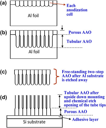
After the anodization process, the top side of the AAO layer was glued onto Si substrate using thermoplastic adhesive (Electron Microscopy Sciences, PA; crystalbond) for ease of handling. The Al substrate that supported the AAO layer was then selectively etched and removed using a mixed HCl and CuCl2 solution for a few tens of minutes until the reaction ended. The AAO barrier layer near the bottom of the anodized pores (now the top surface as the sample was mounted upside down on Si substrate) was then removed by pore-widening chemical etch solution (5 wt% phosphoric acid). The microstructure was then examined under scanning electron microscope (Phillips; XL30 ESEM). Overall fabrication processes are schematically illustrated in Fig. 1. The Cr sputter deposition was performed using direct current sputtering for a nominal thickness of ~5 nm.
Schematic illustration of nanotubular AAO fabrication. (a) MA to form porous AAO layer in 0.3 M sulfuric acid, (b) HA to form tubular AAO layer, (c) selective aluminum removal by etching in (CuCl2 + HCl) solution, (d) attaching AAO upside down on Si substrate and pore-widening etch in 5 wt% phosphoric acid.

B. Cell culture assay for adhesion and viability
For cell culture studies, MC3T3-E1 mouse osteoblast (CRL-2593, subclone 4, ATCC, Manassas, VA) bone cells were used. Cell growth media consisted of alpha minimum essential medium (α-MEM; Invitrogen, Carlsbad, CA) in the presence of 10% fetal bovine serum (FBS; Cellgro, Antioch, IL) and 1% penicillin-streptomycin (PS; Invitrogen). The cells were incubated under the standard 37 °C, 5% CO2 environment. When the concentration of the MC3T3-E1 osteoblastic cells reached ~3 × 10⁵ cells/mL, they were seeded onto the substrate of interest (electropolished flat Al versus AAO nanotube surface), which were placed individually in a 12-well polystyrene plate and stored in a CO2 incubator for 24 h. The concentration of the cells seeded onto the specimen substrate was ~5 × 10⁴ cells/well. Next, to observe cell adhesion, spreading, morphology, and viability of the attached cells, a fluoroscein diacetate (Sigma, MO; FDA) staining was conducted. The cells on the substrates were washed with 1X PBS (phosphate-buffered solution pH 7.4, Invitrogen) and incubated for ~5 min with FDA stock (5 mg dissolved in 1 mL acetone) dissolved in 1X PBS (10 μL/10 mL), and washed once more. The samples were then inverted onto cover-slips, mounted, visualized, and photographed using a green filter by a fluorescence microscope. (DM IRB; Leica Co., Deerfield, IL).
III. RESULTS AND DISCUSSION
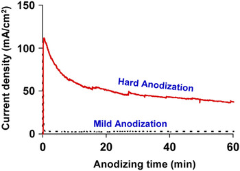
Conventional MA for AAO formation is associated with a relatively low current density over the entire anodizing period, but there is an initial current jump followed by a rapid drop within a few tens of seconds at the beginning stage. In the case of HA, however, a large amount of current flows at the beginning and it is slowly decreased over the anodizing time span, as shown in Fig. 2. High current during the HA process ensures not only fast AAO film growth but also highly ordered AAO cells, as will be discussed later. However, it is worthwhile to mention that samples should be preanodized in MA condition to produce a certain thickness of porous AAO film layer before HA. Otherwise, undesirable local oxide thickening or dielectric breakdown can readily occur during HA.
Representative anodic current changes during anodization experiments. MA (black dotted line) was conducted at 25 V in 0.3 M sulfuric acid at 1 °C, and HA (red solid line) was conducted at 40V in 0.01 M sulfuric acid. MA for 30 min led to the porous AAO structure, which was used as the basis to start the subsequent HA.

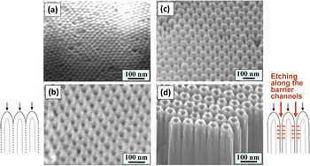
The SEM micrographs in Fig. 3 compare conventional porous AAO and newly obtained nanotubular AAO by HA and nanotube tip etching. In the case of conventional porous AAO, hexagonally ordered AAO pores are vertically grown in the underlying Al substrate under the well-known self-assembly condition. The pore channels are straight and parallel to each other, and the bottom of each vertical pore is closed with a hemispherical end that forms a continuous oxide layer over the whole anodized area, which is known as a barrier layer,Reference Keller, Hunter and Robinson21 as indicated in Fig. 3(a). The SEM image in Fig. 3(a) represents the top view of the upside down barrier layer for the porous AAO sample after MA with 0.3 M sulfuric acid at 25 V. The porous AAO structure after the barrier layer is removed is given in Fig. 3(b).
SEM images showing: (a) top view of upside down barrier layer for the porous AAO after MA with 0.3 M sulfuric acid at 25 V, (b) porous structure after the barrier layer is removed, (c) top view of upside down tubular AAO right after HA at 0.01 M sulfuric acid 40 V, (d) top view SEM after the nanotube tip is etched away and the tubular geometry is realized. The schematics for porous AAO formation mechanism are presented on the left of image (b) and the mechanism of nanotube formation is illustrated by the schematics on the right side of image (d).

In the case of HA, the barrier layer exposed after the Al substrate removal contains a significant depth of recessed voids, which were formed at between-cell triple junctions, as shown in Fig. 3(c). The image of Fig. 3(c) was obtained by HA at 0.01 M sulfuric acid 40 V. The SEM image in Fig. 3(d) is obtained after the nanotube tip is etched away and the tubular geometry is realized. The mechanisms of microstructural formation for porous AAO versus alumina nanotubes are schematically illustrated on the left of image (b) and on the right of image (d), respectively.
The void structure in Fig. 3(c) appears to play a significant role in the separation of neighboring AAO nanotubes from each other during pore-widening chemical etching, as seen in Figs. 3(c) and 3(d). Voids were often observed at the triple cell junctions especially after the HA. Possible mechanisms for void formation were proposed by several groups,Reference Lee, Schwirn, Steinhart, Pippel, Scholz and Gösele11, Reference Zhao, Chan, Yelon and Veres17, Reference Macdonald22–Reference Habazaki, Shimizu, Skeldon, Thompson and Wood27 which can be summarized as follows: (i) electrochemically unfavorable oxygen gas formation and their entrapment along cell boundaries during fast AAO growth; (ii) compositional difference between inner and outer pore wall, which can lead to a different dissolution rate in pore-widening solution; (iii) lower density at triple cell junction due to repulsive force arising from volume expansion during HA; and (iv) accumulated compressive stress along the cell boundaries, and combination of the above. We presume that our nanotube structure formation is based on one or more of these mechanisms. By virtue of the existence of void channels, pore-widening solution could now penetrate through void channels and, therefore, could etch the outer pore walls helping to completely separate the nanotubes from each other. The etching of the inner wall of the AAO cell was retarded due to the closed configuration of the barrier layer at the beginning of pore-widening treatment. Later, when the nanotube tip is dissolved away, the etching solution could wet the inner pore walls and start etching the walls (see the schematic illustrations in Fig. 3).
Our well-separated nanotube array structure, Figs. 3–6, could be attributed to different dissolution rates of inner versus outer pore walls due to their compositional difference. In addition, the presence of the barrier layer covering the nanotube tip (after removing the Al substrate material) delays the inner wall etching while outer pore walls are continuously being etched through void channels at the triple junctions from the very beginning of the chemical etching, which makes it possible to obtain a good nanotube separation from each other.
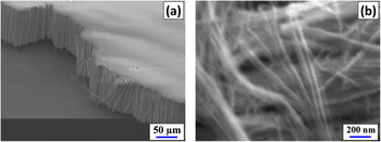
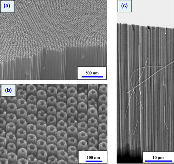
SEM image of freestanding AAO nanotubes placed onto Si substrate (after removal of Al substrate); (a) low and (b) high magnification, respectively. Some of the loose nanotubes imply a mechanical robustness as they can be bent without fracture.

Oblique view of SEM image of vertically aligned periodic AAO nanotubes. (a) Low magnification image, (b) high magnification image showing the nanotube and hole dimension, (c) cross-sectional SEM showing the aligned nature of the AAO nanotubes and an example bent (mechanically flexible) behavior of a separated individual alumina nanotube. Highly ordered hexagonal arrangement was obtained by HA (at 40 V with 0.01 M sulfuric acid), followed by chemical etching in 5 wt% phosphoric acid.

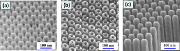
SEM images of vertically aligned periodic AAO nanotubes as (a) hard-anodized, tip-closed nanotube geometry, (b) after chemical etching to open the nanotube tip, and (c) after additional Cr sputter deposition to intentionally reclose the nanotube entrance. An intermediate, partially blocked nanotube structure is obtained if the sputtering time is reduced.

Highly ordered AAO nanotube formation as reported in this work could be associated with high current evolution, directly related to high electric field across barrier layer near the pore bottom. The current density during anodization is dependent on various parameters and the applied electric field, i.e.,

where both j 0 and β are temperature- and material-dependent parameters and E is the effective electric field.Reference Lohrengel28
Another interesting observation regarding AAO nanotubes obtained in this work is that we can obtain high-aspect-ratio (diameter to length) AAO nanotubes of greater than ~1000. Some of the loose nanotubes in Figs. 4 and 5 indicate that the AAO nanotubes can have robust mechanical properties as individual nanotubes can be seen bent or curved without fracture. Because of the dielectric nature of Al2O3 nanotubes, there is some electron charging effect during SEM examination, which makes the image slightly blurry at high magnification, Fig. 4(b). The sample was anodized at 40 V using 0.01 M sulfuric acid, followed by chemical etching by immersing in the mixed CuCl2 + HCl solution for 4 h at 20 °C for removal of Al substrate. A pore-widening etching treatment removes the barrier layer and reveals the nanotube geometry. Figure 5 shows the low magnification and high magnification SEM images of the AAO nanotubes.
In previous research described in the literature, various attempts have been made to obtain individual Al2O3 nanotubes, for example, by using atomic layer deposition of aluminum oxide material on organic nanowires,Reference Huang, Xie, Wu, Yang, Shi, Siu and Chu29 partial chemical dissolution and ultrasonic vibration of porous AAO,Reference Wang, Kei, Yu and Perng30 and hydrothermal synthesis.Reference Lu, Lv, Xu, Guo, Hou, Hu and Huang31 However, these methods to obtain isolated AAO nanotubes are somewhat complicated and have various processing and structural limitations when high-aspect-ratio nanotubes are needed. Our HA-based approach is a convenient technique for fabrication of alumina nanotubes having uniform tube diameter and tailored tube length. It would be interesting to take these individual Al2O3 nanotubes for mechanical property evaluations and related nanomechanics studies.
The Al2O3 nanotube arrays that we have fabricated exhibit uniform and reproducible dimensions, and a quite high aspect ratio (diameter of ~80 nm, height of ~100 μm, aspect ratio >~1000). The SEM micrographs in Fig. 5 clearly indicate the high aspect ratio. It is also seen that the Al2O3 ceramic nanotubes, if individually separated, can be mechanically flexible. Such a flexible nature can be useful for using the Al2O3 nanotube array as a component of tactile shear sensors for robotics, air of fluid flow sensors, and security sensors, similarly as with carbon nanotube shear sensors.Reference Jin32, Reference Deck, Ni, Vecchio and Bandaru33 These aligned Al2O3 nanotubes can be surface metalized with highly conductive metals or magnetic materials, e.g., by sputter deposition or atomic layer deposition, for various other applications such as electron field emitters, electrical interconnects, and sensors and actuators.
Such high-aspect-ratio nanotubes provide a very large surface area, especially since both the inside and outside diameter surfaces can be used, which is not the case for simple AAO pore structures. The large surface area can be exploited for enhanced catalytic reactions (if surface-coated with a very thin catalyst material such as Pt), and can assist in increasing the amount of drug molecules adsorbed on the surface. Together with the large empty space within the nanotube pores as well as the space between the nanotubes in the high aspect nanotube bundles, this can be useful for storage of drugs and other chemicals for controlled slow release, similarly as for the vertically aligned Si nanowire array structure.Reference Brammer, Choi, Oh, Cobb, Connelly, Loya, Kong and Jin34
As an example of potential applications, a model antibiotics drug, amoxicillin whose size is smallReference Vallet-Regi, Doadrio, Doadrio, Izquierdo-Barba and Perez-Pariente35 (~0.8 nm) was loaded into the Al2O3 nanotubes, and drug release experiments were conducted. Preliminary data indicates that a controlled and sustained drug release can be accomplished for a long period of time extending over five weeks, which is a promising trend. The details of the drug release study will be reported in future publications. Factors affecting sustained release of drugs or catalyst molecules from the AAO nanotubes include the physical dimension of nanotube storage space, such as diameter, length, and surface area as well as the surface chemistry of platform and its interaction with the stored material itself. Alteration of the nanotube pore entrance dimension could also be important; for example, an intentional partial blockage of the nanotube pore entrance can be contemplated using a deposition of organic or inorganic material to reduce the diffusion rate of drug release. Shown in Figs. 6(a)–6(c) is an example manipulation of nanotube pore entrance dimension by processing approaches. The pore-widening process for the AAO nanotubes opens up the nanotube tip completely, as shown in Fig. 6(b). Of course, a partial nanotube tip opening can be obtained by shorter time pore-widening treatment so as to provide a smaller diameter nanotube entrance, which would certainly enable a slower-rate, time-extended drug release. Alternatively, a postdeposition of additional material onto the open nanotubes can be used to partially or completely block the nanotube entrance. An example is shown in Fig. 6(c) where it is shown that the use of chromium sputter deposition can lead to the intentional blockage of the nanotube entrance, as shown in Fig. 6(c). The amount of Cr sputtering can be adjusted to achieve any desired nanotube pore entrance dimension for a selected drug release rate.
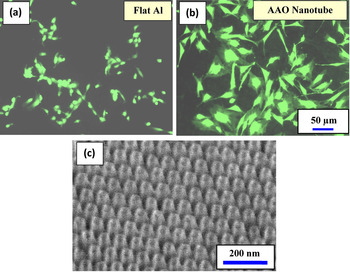
For cell growth and proliferation for various biomedical applications such as tissue engineering, bone growth, stem cell differentiation control, an important first step is for the cells to adhere strongly on the substrate. Such strongly adhered/anchored cells are likely to function more actively and proliferate better. Nanostructured architechure of this nature can be used in various biological applications, such as implant surface coatings for enhanced cell activities. It is well known that the oxide layer on metallic implants is responsible for the bone bonding and natural bone integrating characteristics of orthopedic implants.Reference Feng, Chen, Qi, He, Zhao and Zhang36 Therefore, new research aims have recently been geared toward optimizing these properties to promote enhanced osseointegrationReference Popat, Leoni, Grimes and Desai37 by modifying and improving this oxide layer. Oxide nanostructures such as vertically aligned nanotubes can provide significantly enhanced osteoblast cell adhesion and bone growth, for example, TiO2 nanotubes near the dimension of ~80–100 nm diameter.Reference Oh, Daraio, Chen, Pisanic, Finones and Jin38, Reference Brammer, Oh, Cobb, Bjursten, van der Heyde and Jin39 Therefore, we have also investigated the potential use of our alumina nanotube array structure as an implant surface coating by employing an in vitro cell adhesion assay. Shown in Fig. 7 are comparative osteoblast (bone) cell adhesion images for flat Al2O3 control substrate [Fig. 7(a)] versus Al2O3 nanotube arrays [Fig. 7(b)]. An FDA viability marker was used to stain the cytoplasm of osteoblast cells cultured on the different surfaces.
Osteoblast (bone) cell viability determined by FDA (live fluorescent staining, green color) after 24 h of culture time on (a) flat Al2O3 and on (b) Al2O3 nanotubes. Clearly, the cell adhesion/spreading are significantly enhanced on the nanotube surface. (c) Oblique view SEM image of vertically aligned highly periodic AAO nanotubes for cell culture.

Osteoblast (bone) cell adhesion after 24 h of culture time is much more pronounced on the Al2O3 nanotube substrate compared to a flat Al2O3 control substrate, and it is evident that the cell adhesion and spreading is significantly enhanced on the nanotube surface. These primary studies suggest that the AAO nanotube surface used as a possible orthopedic implant surface is an attractive template for improving the osteoblast response. The AAO nanotube surface, with a wide array of configurations, sizes, and shapes, can be useful for parallel experiments looking further into osteoblast response, functionality, and matrix production for improved osseointegration. The oblique view SEM image of vertically aligned, highly periodic AAO nanotubes used for the osteoblast cell culture is shown in Fig. 7(c). The nanotube sample was anodized at 35 V using 0.06 M sulfuric acid. The pore-widening treatment was conducted with 5 wt% phosphoric acid at 20 °C.
IV. SUMMARY
Highly hexagonally ordered, vertically parallel aluminum oxide nanotube array was fabricated via the HA technique. Due to the high current anodizing process, noticeable voids are formed along the AAO cell boundaries located at triple cell junction, which enhances the separation of adjacent nanotubes during the pore-widening process.
The Al2O3 nanotube arrays as fabricated exhibit a uniform and reproducible dimension, and a quite high aspect ratio of greater than ~1000. The nanotubes appear to be mechanically flexible. Such high-aspect-ratio, mechanically robust, large-surface-area nanotube array structure can be useful for many technical applications, including shear tactile sensors, efficient catalyst supports, chemical reactant releasing materials, and drug storage and slow release biomedical devices.
ACKNOWLEDGMENTS
We wish to acknowledge the financial support of this work by NSF-Nanomanufacturing Division (CMMI No. 0856674), CMRR (Center for Magnetic Recording Research) at UC San Diego, National Research Foundation (NRF) grant through World Class University Program (R33-2008-000-10025-0), Air Force Office of Scientific Research-Ministry of Science and Technology (AFOSR-MOST) Program, and Center for Nanostructured Materials Technology (CNMT) Grant Frontier R&D Program.