1 Introduction
Microscopic flow generation lies at the root of many technological and biological processes. With the advent of microfluidic manipulation techniques, fluids flowing in narrow channels may be used for medical diagnostics, biological sensing and nano-scale chemical synthesis, and it thus becomes essential to induce and control flow within a confined geometry (Squires & Quake Reference Squires and Quake2005; Whitesides Reference Whitesides2006). Classically, this has been achieved by imposing a global external pressure gradient in the system or by surface forcing, either using electrokinetic effects or by generating stresses at boundaries to locally drive the flow. The latter mechanism is widely exploited by biological systems. Coordinated beating of biological flagella leads to self-propulsion of micro-swimmers (Brennen & Winet Reference Brennen and Winet1977; Lauga & Powers Reference Lauga and Powers2009). A complementary process of microscale pumping involves directional flow driven by boundaries, a mechanism used, for example, in embryonic development (Hirokawa, Okada & Tanaka Reference Hirokawa, Okada and Tanaka2009; Montenegro-Johnson et al. Reference Montenegro-Johnson, Baker, Smith and Lopes2016), in the mammalian reproductive tract (Halbert, Tam & Blandau Reference Halbert, Tam and Blandau1976) or for the transport of mucus in human lungs (Sleigh, Blake & Liron Reference Sleigh, Blake and Liron1988). Recently, artificial devices have been designed in which surface flow is generated by flapping flagella of entrapped bacteria (Gao et al. Reference Gao, Li, Chen and Zhang2015).
In a coarse-grained view, all of these surface-driven processes share the common feature that the bulk flow is generated by imposing the motion of the fluid on the confining boundary. Classically, phoretic motion is induced by externally imposed gradients, such as electric field, temperature or concentration (Anderson & Prieve Reference Anderson and Prieve1984). In artificial biomimetic systems, this may also be achieved using phoretic effects, where the interactions between a surface and an external field gradient create a local flow in the close vicinity of the boundary (Derjaguin et al. Reference Derjaguin, Sidorenkov, Zubashchenkov and Kiseleva1947; Anderson Reference Anderson1989), which then may be used for self-propulsion (Golestanian, Liverpool & Ajdari Reference Golestanian, Liverpool and Ajdari2007; Howse et al. Reference Howse, Jones, Ryan, Gough, Vafabakhsh and Golestanian2007; Sharifi-Mood, Koplik Maldarelli Reference Sharifi-Mood, Koplik and Maldarelli2013; Michelin & Lauga Reference Michelin and Lauga2014), migration of particles in externally imposed chemical gradients or flow generation (Gao, Pei & Wang Reference Gao, Pei and Wang2012). Local directional flow may be achieved using chemical micropatterning (Yadav et al. Reference Yadav, Duan, Butler and Sen2015), anisotropic wettability of the channel surface (Wang et al. Reference Wang, Wang, Ge, Xue, Ye, Chen, Li, Zhang and Yang2015) or by spatially varying surface charges of the walls (Stroock & Whitesides Reference Stroock and Whitesides2003).
An alternative method to locally induce phoretic flow with chemical patterning is to exploit geometrical asymmetries in the channel walls (Michelin et al. Reference Michelin, Montenegro-Johnson, De Canio, Lobato-Dauzier and Lauga2015; Yang, Ripoll & Chen Reference Yang, Ripoll and Chen2015). In this paper, we further explore this concept by presenting a model system in which the internal flow may be fully controlled by the geometry. We consider a cavity consisting of two eccentric cylinders and calculate the flow generated by the chemical activity of its surfaces. Assuming uniform chemical activity of the walls, where the solute is consumed (or released) at a fixed rate, a fully analytical solution for the concentration and flow fields may be obtained. We determine the flux in the resulting flow as a function of the cavity geometry, characterised by the size ratio of the cylinders and the eccentricity in their position. An optimal configuration can be identified in which the fluid motion is maximum. An important aspect of the considered system is that the flow rate may be controlled solely by displacing the inner cylinder from a symmetric configuration, where there is no motion by symmetry, to the most eccentric, which maximises the volumetric flux of the fluid within. This system thus represents a tunable internal phoretic pump.
This paper is organised as follows. The general framework of phoretic motion and its solution using bipolar coordinates are first presented in § 2. In § 3, we analyse the resulting flow field and optimise the geometry to achieve the maximal possible rate of the circulating flow. Finally, § 4 summarises the main findings and presents some perspectives.
2 Phoretic flow generation between two eccentric cylinders
2.1 Continuum phoretic framework
We follow the continuum framework of phoretic motion (Golestanian et al.
Reference Golestanian, Liverpool and Ajdari2007; Jülicher & Prost Reference Jülicher and Prost2009; Sabass & Seifert Reference Sabass and Seifert2012) and consider the two-dimensional flow generated in a cavity contained between two eccentric and chemically homogeneous cylinders of circular cross-section
 $\mathscr{S}_{1}$
and
 $\mathscr{S}_{2}$
, filled by a fluid of dynamic viscosity
 ${\it\eta}$
and density
 ${\it\rho}$
, containing a solute species of local concentration
 $C$
and diffusivity
 ${\it\kappa}$
. Assuming that the chemical properties of the outer wall maintain a uniform concentration
 $C_{0}$
on
 $\mathscr{S}_{1}$
, we focus in the following on the relative concentration
 $c=C-C_{0}$
. The chemical activity of the inner wall
 $\mathscr{A}$
quantifies the fixed rate of solute release (
 $\mathscr{A}>0$
) or absorption (
 $\mathscr{A}<0$
) at the surface:
 $$\begin{eqnarray}{\it\kappa}\boldsymbol{n}\boldsymbol{\cdot }\boldsymbol{{\rm\nabla}}c=-\mathscr{A}\quad \text{on}~\mathscr{S}_{2},\end{eqnarray}$$
with
 $\boldsymbol{n}$
being a unit vector normal to the surface. Because of the short-range interaction of solute molecules with the cavity boundary, local concentration gradients result in pressure forces imbalance and the fluid being set into motion. Assuming that the interaction-layer thickness is small compared with the cavity dimensions, the classical slip-velocity formulation may be used (Anderson Reference Anderson1989; Golestanian et al.
Reference Golestanian, Liverpool and Ajdari2007), and local solute gradients result in a net slip velocity
 $$\begin{eqnarray}\boldsymbol{u}=\mathscr{M}(\mathbf{1}-\boldsymbol{n}\boldsymbol{n})\boldsymbol{\cdot }\boldsymbol{{\rm\nabla}}c\quad \text{on}~\mathscr{S}_{j},\quad j=1\text{ or }2,\end{eqnarray}$$
which drives a flow within the cavity. Here,
 $\mathscr{M}$
is the local phoretic mobility of the cylinder surfaces. It should be noted that, since the concentration is uniform on the outer boundary
 ${\it\tau}={\it\tau}_{1}$
, equation (2.2) results in the classical no-slip boundary condition there (
 $\boldsymbol{u}=\mathbf{0}$
). When the Péclet number
 $Pe=\mathscr{UR}/{\it\kappa}$
is small enough (e.g. small solute molecules), the solute dynamics is purely diffusive and is thus governed by the Laplace equation,
 $$\begin{eqnarray}{\rm\nabla}^{2}c=0,\end{eqnarray}$$
in the fluid domain. Here,
 $\mathscr{R}$
denotes the radius of
 $\mathscr{S}_{1}$
, chosen as the characteristic length in this work, and
 $\mathscr{U}=|\mathscr{AM}|/{\it\kappa}$
is the characteristic phoretic velocity generated along
 $\mathscr{S}_{2}$
. Provided that inertial effects are negligible (i.e. the Reynolds number
 $Re={\it\rho}\,\mathscr{U}\mathscr{R}/{\it\eta}\ll 1$
), the flow and pressure fields satisfy the incompressible Stokes equations
 $$\begin{eqnarray}\boldsymbol{{\rm\nabla}}\boldsymbol{\cdot }\boldsymbol{u}=0,\quad {\it\eta}{\rm\nabla}^{2}\boldsymbol{u}=\boldsymbol{{\rm\nabla}}p.\end{eqnarray}$$
The diffusive Laplace problem for the solute thus effectively decouples from the hydrodynamic problem and may be solved independently. Its solution for the concentration
 $c$
can be used to compute the slip flow along
 $\mathscr{S}_{2}$
, equation (2.2), which then determines the flow field within the cavity by solving equation (2.4).
The problem is non-dimensionalised as follows: with
 $\mathscr{R}$
and
 $\mathscr{U}$
chosen as the characteristic length and velocity respectively, the characteristic concentration scale is set by
 $|\mathscr{A}|\mathscr{R}/{\it\kappa}$
and the characteristic pressure reads
 ${\it\eta}|\mathscr{A}\mathscr{M}|/\mathscr{R}{\it\kappa}$
.
2.2 Formulation of the non-dimensional problem
The two-dimensional cavity
 ${\it\Omega}_{f}$
is enclosed between two eccentric cylindrical surfaces
 $\mathscr{S}_{1}$
and
 $\mathscr{S}_{2}$
of respective non-dimensional radii
 $R_{1}=1$
and
 $R_{2}$
. The centres of the cylinders are offset by a distance
 $d$
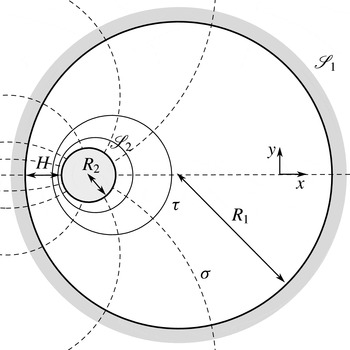
(figure 1). The diffusion problem for solute concentration reads
 $$\begin{eqnarray}{\rm\nabla}^{2}c=0\quad \text{in}~{\it\Omega}_{f},\end{eqnarray}$$
 $$\begin{eqnarray}c=0\quad \text{on}~\mathscr{S}_{1},\quad \boldsymbol{n}\boldsymbol{\cdot }\boldsymbol{{\rm\nabla}}c=-A\quad \text{on}~\mathscr{S}_{2},\end{eqnarray}$$
with the dimensionless activity
 $A=\mathscr{A}/|\mathscr{A}|$
, and the associated hydrodynamic flow problem may now be formulated as
 $$\begin{eqnarray}{\rm\nabla}^{2}\boldsymbol{u}=\boldsymbol{{\rm\nabla}}p\quad \text{in}~{\it\Omega}_{f},\end{eqnarray}$$
 $$\begin{eqnarray}\boldsymbol{u}=\mathbf{0}\quad \text{on}~\mathscr{S}_{1},\quad \boldsymbol{u}=M(\mathbf{1}-\boldsymbol{n}\boldsymbol{n})\boldsymbol{\cdot }\boldsymbol{{\rm\nabla}}c\quad \text{on}~\mathscr{S}_{2},\end{eqnarray}$$
with
 $M=\mathscr{M}/|\mathscr{M}|=\pm 1$
being the dimensionless mobility.
Notation for the annular cavity consisting of two non-coaxial cylinders. Bipolar coordinates are represented by surfaces of constant
 ${\it\tau}$
(solid) and
 ${\it\sigma}$
(dashed). The surfaces
 ${\it\tau}={\it\tau}_{1}$
and
 ${\it\tau}={\it\tau}_{2}$
correspond to the boundaries of the outer and inner cylinder respectively.

2.3 Computation of the flow field
2.3.1 Bipolar coordinates
It is natural in this problem to introduce the bipolar cylindrical coordinate system,
 $-\infty <{\it\tau}<\infty$
,
 $-{\rm\pi}\leqslant {\it\sigma}<{\rm\pi}$
, related to the Cartesian coordinates
 $(x,y)$
by
 $$\begin{eqnarray}x=\frac{a\sin {\it\sigma}}{\cosh {\it\tau}-\cos {\it\sigma}},\quad y=\frac{a\sinh {\it\tau}}{\cosh {\it\tau}-\cos {\it\sigma}},\end{eqnarray}$$
with
 $x$
being horizontal in figure 1, and the scale factors given by
 $$\begin{eqnarray}h_{{\it\sigma}}=h_{{\it\tau}}=h=\frac{a}{\cosh {\it\tau}-\cos {\it\sigma}}=\frac{a}{\sinh {\it\tau}}\left(1+2\mathop{\sum }_{n=1}^{\infty }\text{e}^{-n{\it\tau}}\cos n{\it\sigma}\right).\end{eqnarray}$$
The last equality follows from representation of the scale factor
 $h$
in terms of a Fourier series in
 ${\it\sigma}$
. Since
 $h$
is an even function of
 ${\it\sigma}$
, the series has only cosine terms. The unit vectors
 $\boldsymbol{e}_{{\it\tau}}$
and
 $\boldsymbol{e}_{{\it\sigma}}$
, normal to the isolines of
 ${\it\tau}$
and
 ${\it\sigma}$
respectively, are given by
 $\partial \boldsymbol{x}/\partial {\it\tau}=h_{{\it\tau}}\boldsymbol{e}_{{\it\tau}}$
and
 $\partial \boldsymbol{x}/\partial {\it\sigma}=h_{{\it\sigma}}\boldsymbol{e}_{{\it\sigma}}$
, and form an orthonormal basis in 2D.
The isolines
 ${\it\tau}={\it\tau}_{0}$
are circles of radius
 $a/|\sinh {\it\tau}_{0}|$
centred on the
 $y$
-axis at
 $y=a\coth {\it\tau}_{0}$
. In the following, we choose
 ${\it\tau}_{1,2}>0$
, i.e. both circular boundaries lie in the upper half-plane; their centres are separated by a distance
 $d$
. The parameters of the system
 $(d,R_{1},R_{2})$
thus satisfy
 $$\begin{eqnarray}R_{1,2}=\frac{a}{\sinh {\it\tau}_{1,2}},\quad d=a(\coth {\it\tau}_{1}-\coth {\it\tau}_{2}).\end{eqnarray}$$
The closest distance between the circles, the gap width
 $H$
, is given by
 $H=R_{1}-R_{2}-d$
.
2.3.2 Solute diffusion
The Laplace equation for the concentration field in two dimensions becomes
 $$\begin{eqnarray}\frac{1}{h^{2}}\left(\frac{\partial ^{2}c}{\partial {\it\tau}^{2}}+\frac{\partial ^{2}c}{\partial {\it\sigma}^{2}}\right)=0.\end{eqnarray}$$
The Dirichlet boundary condition on the outer cylinder is
 $c({\it\tau}_{1},{\it\sigma})=0$
. Noting that
 $\boldsymbol{n}({\it\tau})=-\boldsymbol{e}_{{\it\tau}}$
for
 ${\it\tau}={\it\tau}_{2}$
, the flux boundary condition, equation (2.6), follows as
 $$\begin{eqnarray}\boldsymbol{e}_{{\it\tau}}\boldsymbol{\cdot }\boldsymbol{{\rm\nabla}}c=\frac{1}{h}\frac{\partial c}{\partial {\it\tau}}=A.\end{eqnarray}$$
Equation (2.12) is separable, and using (2.10) its solution satisfying these boundary conditions is
 $$\begin{eqnarray}\displaystyle c({\it\tau},{\it\sigma})=AR_{2}({\it\tau}-{\it\tau}_{1})+2AR_{2}\mathop{\sum }_{n=1}^{\infty }\frac{\text{e}^{-n{\it\tau}_{2}}}{n}\frac{\sinh [n({\it\tau}-{\it\tau}_{1})]}{\cosh [n({\it\tau}_{1}-{\it\tau}_{2})]}\cos n{\it\sigma}. & & \displaystyle\end{eqnarray}$$
2.3.3 Stokes flow
The Stokes flow problem may be conveniently formulated in bipolar cylindrical coordinates using the stream function
 ${\it\psi}({\it\tau},{\it\sigma})$
, such that
 $$\begin{eqnarray}u_{{\it\tau}}=-\frac{1}{h}\frac{\partial {\it\psi}}{\partial {\it\sigma}},\quad u_{{\it\sigma}}=\frac{1}{h}\frac{\partial {\it\psi}}{\partial {\it\tau}}.\end{eqnarray}$$
The stream function is related to the flow vorticity by
 ${\it\omega}=-{\rm\nabla}^{2}{\it\psi}$
. Since the vorticity
 ${\bf\omega}=\boldsymbol{{\rm\nabla}}\times \boldsymbol{u}$
is harmonic,
 ${\rm\nabla}^{2}{\bf\omega}=0$
, we conclude that
 ${\it\psi}$
satisfies the biharmonic equation
 $$\begin{eqnarray}\boldsymbol{{\rm\nabla}}^{4}{\it\psi}={\rm\nabla}^{2}{\rm\nabla}^{2}{\it\psi}=0,\end{eqnarray}$$
with the Laplacian given in bipolar cylindrical coordinates in (2.12). As shown by Jeffery (Reference Jeffery1921), it is most convenient to consider the function
 ${\it\Psi}={\it\psi}/h$
for which (2.16) becomes a linear equation with constant coefficients
 $$\begin{eqnarray}\left(\frac{\partial ^{4}}{\partial {\it\tau}^{4}}+2\frac{\partial ^{4}}{\partial {\it\tau}^{2}\partial {\it\sigma}^{2}}+\frac{\partial ^{4}}{\partial {\it\sigma}^{4}}-2\frac{\partial ^{2}}{\partial {\it\tau}^{2}}+2\frac{\partial ^{2}}{\partial {\it\sigma}^{2}}+1\right){\it\Psi}=0,\end{eqnarray}$$
with solution also given by Jeffery (Reference Jeffery1922). The boundary conditions on the cylinders are then written in terms of
 ${\it\Psi}={\it\psi}/h$
using (2.15a,b
), and simplify, noting that because of symmetry and boundary conditions, the axis of symmetry and both cylinders are on the same streamline. Therefore,
 ${\it\Psi}({\it\tau}_{1,2},{\it\sigma})=0$
. The remaining velocity boundary conditions read
 $$\begin{eqnarray}\displaystyle & \displaystyle \frac{\partial {\it\Psi}}{\partial {\it\tau}}=0,\quad \text{on}~{\it\tau}={\it\tau}_{1}, & \displaystyle\end{eqnarray}$$
 $$\begin{eqnarray}\displaystyle & \displaystyle \frac{\partial {\it\Psi}}{\partial {\it\tau}}=u_{{\it\sigma}}({\it\tau}_{2},{\it\sigma})\quad \text{on}~{\it\tau}={\it\tau}_{2}. & \displaystyle\end{eqnarray}$$
The slip velocity on the surface of the inner cylinder is obtained from (2.2) using the solution of the solute concentration problem (2.14) as
 $$\begin{eqnarray}\displaystyle u_{{\it\sigma}}({\it\tau}_{2},{\it\sigma})=\frac{MAR_{2}}{a}\left[(d_{2}-2d_{1}\cosh {\it\tau}_{2})\sin {\it\sigma}+\mathop{\sum }_{n=2}^{\infty }(d_{n+1}+d_{n-1}-2d_{n}\cosh {\it\tau}_{2})\sin n{\it\sigma}\right],\hspace{-6.0pt} & & \displaystyle \nonumber\\ \displaystyle & & \displaystyle\end{eqnarray}$$
with
 $d_{n}=\text{e}^{-n{\it\tau}_{2}}\tanh n({\it\tau}_{2}-{\it\tau}_{1})$
. The resulting stream function reads
 $$\begin{eqnarray}\displaystyle \displaystyle {\it\psi} & = & \displaystyle h{\it\Psi}=\frac{MAR_{2}}{\cosh {\it\tau}-\cos {\it\sigma}}\left[\vphantom{\mathop{\sum }_{n=2}^{\infty }}({\it\alpha}_{1}\cosh 2{\it\tau}+{\it\beta}_{1}+{\it\gamma}_{1}\sinh 2{\it\tau}+{\it\delta}_{1}{\it\tau})\sin {\it\sigma}\right.\nonumber\\ \displaystyle & & \displaystyle \displaystyle +\mathop{\sum }_{n=2}^{\infty }\left({\it\alpha}_{n}\cosh (n+1){\it\tau}+{\it\beta}_{n}\cosh (n-1){\it\tau}\right.\nonumber\\ \displaystyle & & \displaystyle \displaystyle \left.\!\left.+\,{\it\gamma}_{n}\sinh (n+1){\it\tau}+{\it\delta}_{n}\sinh (n-1){\it\tau}\right)\sin n{\it\sigma}\vphantom{\mathop{\sum }_{n=2}^{\infty }}\right],\end{eqnarray}$$
with coefficients listed in appendix A. This explicit form of the stream function may now be used to characterise the flow.
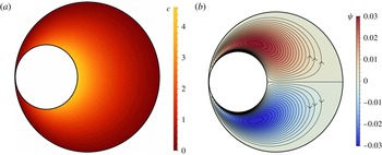
Distribution of solute concentration
 $c$
(a) and stream function
 ${\it\psi}$
(b) within the cavity for
 $R_{2}/R_{1}=0.43,H/H_{max}=0.01$
, and
 $A=1$
(solute released by the inner cylinder) and
 $M=1$
(the flow direction is reversed when
 $AM=-1$
). The isolines of
 ${\it\psi}$
are the streamlines.

3 Results and discussion
In non-dimensional form, the flow resulting from the chemical activity of the bounding surfaces now solely depends on two geometric parameters, namely the relative radii of the cylinders
 $R_{2}/R_{1}$
and the asymmetry parameter
 $d/R_{1}$
controlling the eccentricity. The latter can be alternatively described by the relative gap width,
 $0\leqslant H/R_{1}\leqslant 1-R_{2}/R_{1}$
. The maximal gap width thus reads
 $H_{max}=R_{1}-R_{2}$
.
For the purpose of demonstration, in all of the following figures we truncate the series (2.14) and (2.21) at a finite sufficiently large
 $n$
. A typical solute concentration profile in the eccentric annular cavity is depicted in figure 2. For
 $A>0$
(respectively
 $A<0$
), the requirement of a constant normal gradient at the surface of the inner cylinder, equation (2.6), results in the concentration of solute being highest (respectively lowest) in the central area of the cavity, and decreasing (respectively increasing) along the surface when moving towards the most confined region between the cylinders. In this narrower gap, concentration gradients are lower due to the shorter distances allowed for diffusive transport. As a result, tangential gradients of concentration and slip flow arise on the surface of the inner cylinder. For
 $AM>0$
, they are oriented from the narrower gap to the central part of the cavity. Two stagnation points are found on the axis of symmetry, and the slip flow is maximal on the lateral sides of the inner cylinder.
This boundary forcing generates two counter-rotating cells within the cavity, with the flow speed being maximal at the surface of the inner (driving) cylinder. This is most easily demonstrated in figure 2, where the streamlines are plotted. It should be noted that the flow, and thus its direction, depends on the sign of chemical activity and phoretic mobility of the boundary: if
 $AM>0$
, the vorticity is positive in the upper cell and negative in the lower cell.
An appealing property of the present set-up is the ability to control the magnitude of the flow by tuning the geometry. In the context of constructing an optimal flow-inducing device in such a geometry, it is important to determine which configuration (size ratio and gap width) maximises the strength of flow. For a perfectly centred inner cylinder, the concentration distribution is isotropic within the cavity, leading to no flow forcing and no fluid motion. Eccentricity therefore plays a key role in driving the flow within the cavity, and most asymmetric configurations are expected to stir the fluid most efficiently.
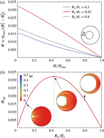
(a) Evolution of the scaled total flux in a circulation cell,
 ${\it\Phi}={\it\psi}_{max}/(R_{1}^{2}-R_{2}^{2})$
, with the relative gap width
 $H/H_{max}$
for
 $R_{2}/R_{1}=0.1$
, 0.43 and 0.8. (b) Evolution of the optimal scaled flux
 ${\it\Phi}_{opt}$
(obtained for touching cylinders) with
 $R_{2}/R_{1}$
. The magnitude of the velocity field is also plotted for three cases (same as above), showing the competing effects of phoretic driving and wall hindrance on the flow.

In order to quantify that intuition and the strength of flow generated by the chemical activity on the surface of the inner cylinder, we calculate the total flux of the circulating fluid. Since the flux across a curve between two points
 $A$
and
 $B$
is the difference of the stream functions,
 ${\it\psi}(B)-{\it\psi}(A)$
, and given that on the surfaces of the cylinders
 ${\it\psi}=0$
, the total flux in the circulation cell is given by the maximal value of the stream function,
 ${\it\psi}_{max}$
, in the fluid. In the following, we focus on the volume flux per unit area of the cavity,
 ${\it\Phi}={\it\psi}_{max}/(R_{1}^{2}-R_{2}^{2})$
, as a measure of flow motion. An alternative interpretation of
 $1/{\it\Phi}$
also provides an estimate of the characteristic stirring time for the fluid, namely a weighted average of the period of fluid particle motion along the streamlines.
For a given size ratio of the cylinders, we find an approximately linear increase of this flux with increasing asymmetry (decreasing the gap size
 $H$
), with a maximum attained in the limit
 $H\rightarrow 0$
regardless of the size ratio (see figure 3
a). This is consistent with the observation that autophoretic particles tend to be strongly repelled from a neighbouring wall, as recently investigated by Uspal et al. (Reference Uspal, Popescu, Dietrich and Tasinkevych2015) for a spherical active particle close to a planar wall. In this limit, we look for the optimal size ratio that maximises the flow rate.
The value of the optimal scaled flux,
 ${\it\Phi}_{opt}$
, depends on the relative sizes of the cylinders. For large size ratios, the motion of the fluid is hindered by the no-slip boundary condition on the outer boundary and leads to small flow. When the inner cylinder gets small, strong gradients induce large slip velocities; however, these are capable of moving only the fluid in their immediate vicinity, resulting in most of the fluid remaining at rest. This is confirmed by figure 3(b), where we plot the dependence on the size ratio of the maximum scaled volumetric flux
 ${\it\Phi}$
(obtained for touching cylinders). Clearly, for size ratios of 0 and 1 the flow ceases, and a maximum is present at
 $R_{2}/R_{1}\approx 0.43$
.
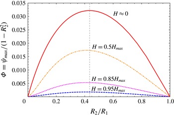
Interestingly, our numerical results show that the optimal size ratio that maximises the flow rate seems not to depend on the asymmetry parameter
 $H/H_{max}$
, and therefore is a universal feature of the system, as shown in figure 4. This suggests that this ratio may be determined likewise in the case when
 $d\approx 0$
, at only a slight asymmetry, and by taking only the
 $n=1$
term in (2.21), as this is enough to grasp the character of the flow in this far-field limit. Numerical solution yields the optimal size ratio
 $R_{2}/R_{1}\approx 0.41$
, which is within 5 % from the value determined at small gap using the full solution.
The dependence of the total flux
 ${\it\Phi}$
on the size ratio shows that the optimal size ratio
 $R_{2}/R_{1}\approx 0.43$
is universal and approximately independent of the gap width
 $H$
between the cylinders.

As an extension to the flow generation problem discussed above, we note that the fixed-flux condition (2.1) may be generalised to a one-step chemical reaction by assuming the activity to be proportional to the local solute concentration,
 $\mathscr{A}=-\mathscr{K}C$
, with a constant reaction rate
 $\mathscr{K}$
(Córdova-Figueroa & Brady Reference Córdova-Figueroa and Brady2008). The relative importance of the reaction rate and diffusive transport of solute is then quantified by the Damköhler number,
 $Da=\mathscr{K}\mathscr{R}/{\it\kappa}$
. For
 $Da\ll 1$
, the diffusion of the solute is fast enough to ensure a homogeneous consumption of solute on the boundaries, while the limit
 $Da\gg 1$
corresponds to slow diffusion being unable to compensate for the fast local reactive effects. As for the propulsion problem, the effect of an increasing Damköhler number on our set-up is a limitation of the inner wall chemical activity by the depletion in solute resulting from the slow diffusion. As a result, the concentration gradients induced in the system are reduced, and therefore the resulting slip velocities are generally lower. The main conclusions of the previous analysis, namely the existence of an optimal configuration for touching cylinders and intermediate size ratio, remain valid nonetheless (not shown).
4 Conclusions
Recent years have brought significant attention to autophoresis as a promising mechanism for microscale fluid manipulation and transport. The production of such miniature devices poses physical challenges which require a deeper understanding of the physical mechanisms underlying the phoretic generation of viscous flows in confined geometries. Our paper provides an example of a system in which the flow can be fully controlled by adjusting its geometric configuration, and a first attempt at optimizing internal flows driven by phoretic effects.
Specifically, we have analysed the model system of a two-dimensional cavity between two eccentric cylinders. Bulk flow circulation can be induced within the cavity from the chemical activity of the walls (i.e. the release/absorption of solute) and their phoretic mobility (i.e. their interaction with local solute content). Neglecting solute advection, the problem has an analytical solution which was presented here in terms of the Stokes flow stream function. By analysing the explicit formulae, an optimal configuration was identified for the system, quantified by the maximal flow rate within the fluid volume, in terms of the position and size of the inner cylinder with respect to the outer one. Replacing the fixed-flux boundary condition by a simple chemical reaction leads to a general decrease of the efficiency of the device but similar overall conclusions.
Our results identify an optimal configuration, namely a maximum eccentricity achieved for two touching cylinders. In that case, the narrowest gap is effectively closed and the geometry of the system resembles that of a circular cavity with an inner protrusion. Optimal flow circulation then results from the concentration gradients enhanced by the local higher curvature of the boundary. This effect of curvature on phoretic flow enhancement is consistent with recent work on phoretic propulsion (Michelin & Lauga Reference Michelin and Lauga2015). The limit of touching cylinders deserves more scrutiny however: when
 $H$
becomes smaller than the typical interaction-layer thickness
 ${\it\lambda}$
, the slip-velocity formulation of phoretic flows, equation (2.2), breaks down, and the above analysis should be replaced by a full description of the solute–wall interactions within the boundary layer.
Acknowledgements
This work was funded in part by a David Crighton Fellowship at the University of Cambridge (M.L.), a Mobility Plus Fellowship from the Polish Ministry of Science and Higher Education (M.L.), the EU through a Marie-Curie CIG grant (E.L.) and the French Ministry of Defense DGA (S.M.).
Appendix A. Coefficients of the stream function
The exact solution for the stream function (2.21) involves the following coefficients which depend solely on
 ${\it\tau}_{1,2}$
:
 $$\begin{eqnarray}\displaystyle & & \displaystyle \displaystyle {\it\alpha}_{1}=X\{2{\rm\Delta}{\it\tau}\cosh 2{\it\tau}_{1}-\sinh 2{\it\tau}_{1}+\sinh 2{\it\tau}_{2}\},\end{eqnarray}$$
 $$\begin{eqnarray}\displaystyle & & \displaystyle \displaystyle {\it\beta}_{1}=X\{2{\it\tau}_{2}-2{\it\tau}_{1}\cosh 2{\rm\Delta}{\it\tau}+\sinh 2{\rm\Delta}{\it\tau}\},\end{eqnarray}$$
 $$\begin{eqnarray}\displaystyle & & \displaystyle \displaystyle {\it\gamma}_{1}=X\{-2{\rm\Delta}{\it\tau}\sinh 2{\it\tau}_{1}+\cosh 2{\it\tau}_{1}-\cosh 2{\it\tau}_{2}\},\end{eqnarray}$$
 $$\begin{eqnarray}\displaystyle & & \displaystyle \displaystyle {\it\delta}_{1}=4X\sinh ^{2}{\rm\Delta}{\it\tau},\end{eqnarray}$$
 $$\begin{eqnarray}\displaystyle & & \displaystyle \displaystyle {\it\alpha}_{n}=Y_{n}\left\{n\sinh [2{\it\tau}_{1}+(n-1){\it\tau}_{2}]-\sinh [2n{\it\tau}_{1}+(1-n){\it\tau}_{2}]\right.\nonumber\\ \displaystyle & & \displaystyle \qquad -\left.(n-1)\sinh (n+1){\it\tau}_{2}\right\}\!,\end{eqnarray}$$
 $$\begin{eqnarray}\displaystyle & & \displaystyle \displaystyle {\it\beta}_{n}=Y_{n}\left\{-(1+n)\sinh (n-1){\it\tau}_{2}-n\sinh [2{\it\tau}_{1}-(n+1){\it\tau}_{2}]\right.\nonumber\\ \displaystyle & & \displaystyle \qquad +\left.\sinh [2n{\it\tau}_{1}-(n+1){\it\tau}_{2}]\right\}\!,\end{eqnarray}$$
 $$\begin{eqnarray}\displaystyle & & \displaystyle \displaystyle {\it\gamma}_{n}=Y_{n}\left\{-n\cosh [2{\it\tau}_{1}+(n-1){\it\tau}_{2}]+\cosh [2n{\it\tau}_{1}+(1-n){\it\tau}_{2}]\right.\nonumber\\ \displaystyle & & \displaystyle \qquad +\left.(n-1)\cosh (n+1){\it\tau}_{2}\right\}\!,\end{eqnarray}$$
 $$\begin{eqnarray}\displaystyle & & \displaystyle \displaystyle {\it\delta}_{n}=Y_{n}\left\{(1+n)\cosh (n-1){\it\tau}_{2}-n\cosh [2{\it\tau}_{1}-(n+1){\it\tau}_{2}]\right.\nonumber\\ \displaystyle & & \displaystyle \qquad -\left.\cosh [2n{\it\tau}_{1}-(n+1){\it\tau}_{2}]\right\}\!,\end{eqnarray}$$
 ${\rm\Delta}{\it\tau}={\it\tau}_{1}-{\it\tau}_{2}$
and
 $$\begin{eqnarray}\displaystyle & & \displaystyle \displaystyle X=\frac{d_{2}-2d_{1}\cosh {\it\tau}_{2}}{8\sinh ^{2}{\rm\Delta}{\it\tau}(1-{\rm\Delta}{\it\tau}\coth {\rm\Delta}{\it\tau})},\end{eqnarray}$$
 $$\begin{eqnarray}\displaystyle & & \displaystyle \displaystyle Y_{n}=\frac{1}{2}\frac{d_{n+1}+d_{n-1}-2d_{n}\cosh {\it\tau}_{2}}{n^{2}-1-n^{2}\cosh 2{\rm\Delta}{\it\tau}+\cosh 2n{\rm\Delta}{\it\tau}}.\end{eqnarray}$$