I. INTRODUCTION
Due to the benefit of light weight, low cost, low profile, high reliability, and ease of integration with active devices, printed planar antenna arrays are desirable for use in applications such as access points for Wireless Local Area Network (WLAN) [Reference Chen, Lan and Hsu1, Reference Chen and Hsu2]. If one wishes to use the entire 5.15–5.825 GHz frequency band of the Institute of Electrical and Electronics Engineers (IEEE) 802.11a standard, and achieve reasonable gain for a specific application, it would not be possible to use standard patch radiators with a corporate microstrip line feed network since such an array would be too narrow band. There are several methods available to enhance the bandwidth of patch type radiators, including an increase in substrate thickness, using parasitic elements, or modifying the slot shape by cutting slots in the patch [Reference Denidni and Hassaine3]. These bandwidth enhancement techniques often involve more complicated design efforts, or cause degradation in some other performance aspect of the antenna, e.g. cross-polarization, pattern symmetry or shape, etc. Previous studies of planar slot array antennas have shown some promise of achieving low cross-polarization, good bandwidth, low side lobe levels, reasonable gain, and high radiation efficiency [Reference Chen, Lan and Hsu1, Reference Chen and Hsu2, Reference Soliman, Brebels, Vanderbosch and Beyne4–Reference Chen and Hsu7]. A possible drawback of printed slots is that they radiate bi-directionally, which can be solved by using an electric conductor ground plane reflector spaced a quarter-wavelength away from the printed slot array, or if low profile construction is required a closely spaced artificial magnetic conductor can be used as reflector as was illustrated in [Reference Joubert, Vardaxoglou, Whittow and Odendaal8].
In [Reference Chen, Lan and Hsu1] an in-line collinear slot array fed by coplanar waveguide (CPW) was presented. The feedlines between the radiating slots are meandered to ensure that any two radiating slots have a one guide wavelength path length between them at resonance, for in-phase excitation. This arrangement can effectively be viewed as the equivalent of an equi-spaced linear array of parallel end-to-end half-wavelength slots. Arrays of six radiating elements in open- and short-ended configurations were designed. A measured impedance bandwidth of 20.3% and a peak gain of 7.3 dBi were achieved for a truncated open-ended array. Another example of a previously published slot array is the open-ended rampart slot array antenna presented in [Reference Chen and Hsu2]. Radiating slots of approximately half guide wavelength, with λ 0/2 spacing, are fed by a slotline feed network. The impedance bandwidths obtained for six element open- and short-ended arrays were 9.6 and 11.1%, with peak gains of 8.2 and 9.0 dBi, respectively. Examples of planar printed slot arrays are the brick-wall slot arrays presented in [Reference Soliman, Brebels, Vanderbosch and Beyne4] and [Reference Soliman, Brebels, Beyne, Delmotte and Vanderbosch5], and the rectangular grid 2 × 2 printed slot array presented in [Reference Joubert and Odendaal6]. The 11-slot array described in [Reference Soliman, Brebels, Vanderbosch and Beyne4, Reference Soliman, Brebels, Beyne, Delmotte and Vanderbosch5] achieved a maximum directivity of 11.3 dB and was matched in two closely spaced narrow bandwidths. For the array in [Reference Joubert and Odendaal6] (no reflector was present, so the antenna radiated bi-directionally) an impedance bandwidth of 12% and a peak gain of 8 dBi were achieved for a 2.4 GHz WLAN design.
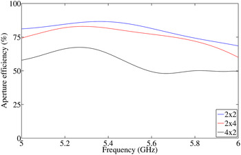
In this paper the authors would like to present results of an investigation into the use of printed slot arrays as an alternative (to patch type arrays) to realize a planar array with reasonable gain and appropriate bandwidth to cover the entire IEEE 802.11a band. Three designs are presented – for a 2 × 2, a 2 × 4, and a 4 × 2 slot array, respectively, all vertically polarized with unidirectional radiation, with simulated and measured results that show good bandwidth, stable radiation patterns across the band, low cross-polarization, and reasonable gain. There is a good agreement between the simulated and measured results. An interesting finding of this investigation was that two of the three slot arrays proposed in this paper have high aperture efficiencies when compared with other arrays suggested for the same (or similar) WLAN application. Higher aperture efficiencies imply that the antenna will occupy less space to achieve the same gain. The typical aperture efficiency of a wideband microstrip array is around 50–65% [Reference Ma and Vandenbosch9]. The 2 × 2 and 2 × 4 slot arrays proposed in this paper have maximum aperture efficiencies of around 80%, which is significantly higher than for example, the wideband E-shaped patch array presented in [Reference Denidni and Hassaine3], the high gain slot dipole array presented in [Reference Iizasa, Pokharel and Yoshitomi10], and the broadband printed compound air-fed array antenna presented in [Reference Wu and Zhang11]. Special cases are possible, as was shown in [Reference Ma and Vandenbosch9], where novel patch arrays were designed with aperture efficiencies in the order of 75–85%. This could only be achieved by using unconventional architectures and a powerful evolutionary optimization technique to optimize specifically for high aperture efficiency. The slot arrays presented in this paper have simple constructions and conventional architectures, and do not require explicit optimization to achieve high aperture efficiencies.
III. GEOMETRY AND DESIGN APPROACH
A) Antenna geometry
The departure point for the design of the center-fed printed slot array was the 2 × 2 etched slot array with corporate slotline feed network in [Reference Joubert and Odendaal6]. The design in [Reference Joubert and Odendaal6] was simplified by changing the four-way slotline feed network to a rectangular arrangement, and the input port was also modified from a CPW input port to a co-axial line input port with a microstrip to slotline transition. The aim was furthermore to keep the design procedure as simple as possible, and to that end it was decided that, where possible, all radiating slot dimensions as well as the widths of the slotline feed structure would be kept uniform. This reduces the amount of variables to be optimized, as well as allow for rapid development of a new antenna array using the proposed procedure.
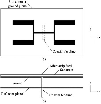
The geometry of the new four element printed planar slot array is shown in Fig. 1. The slot array is etched on one side of a rectangular substrate. The microstrip feedline of the microstrip to slotline transition [Reference Shuppert12] is etched on the opposite side of the substrate and connected to the center-pin of a co-axial transmission line, of which the outer conductor is connected to the slot array ground plane. All the radiating slots are of the same length and width. The feed network slotlines are all the same width, but the line lengths are adjusted to ensure the radiating elements are in phase. Except for the feed point, the array is symmetrical in both the x- and y-planes, as shown in Fig. 1. A finite-size electric conductor reflector is placed a quarter free-space wavelength below the antenna to ensure unidirectional radiation.
Geometry of a four-slot printed planar slot array antenna: (a) top view, (b) side view.

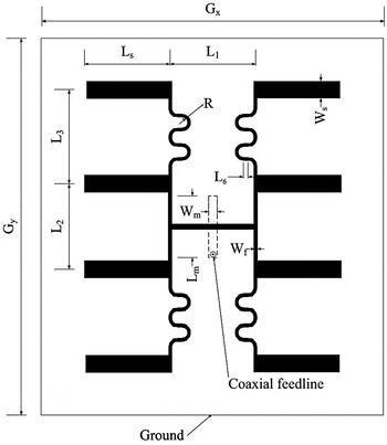
Two larger eight element arrays are also proposed. The 4 × 2 slot array has four additional elements along the y-axis, hybrid-fed from the initial 2 × 2 array elements. In order to maintain the in-phase excitation required for the extended eight element 4 × 2 array, the feed length from the inner elements of the initial 2 × 2 array to the outer radiating slots must be one slotline guide wavelength long. To achieve the one wavelength feedline length for in-phase excitation of radiating slots, as well as a smaller than free-space wavelength spacing between the radiating slots to avoid the occurrence of grating lobes, the feed lines have to be meandered. The feedlines are meandered away from the radiating slots to reduce the disturbance of the flow of current between the resonant half-wavelength slots.
The 2 × 4 rectangular grid slot array has four additional elements along the x-axis, which are in-line series-fed from the initial 2 × 2 array elements. The in-phase excitation of such a proposed expansion of the 2 × 2 array can be achieved by ensuring the centers of the radiating slots are spaced one wavelength apart in the x-direction. Because the slots are approximately half a wavelength long, the feedline would also be required to be approximately half a guide wavelength long. One could have meandered the slotlines between the slots to reduce the inter slot spacing, but in this instance the H-plane element pattern of the slots helps to suppress the grating lobe, and it was decided to use straight slotline sections between the slots.
B) Design approach
The design of the planar printed slot array antenna was performed with CST Microwave Studio. The lengths and widths of all the radiating half-wavelength slots were kept uniform throughout the design, as was the slot feedline width. There was thus only one length and width for the radiating slots (L s and W s ), one width for all the slot feedlines (W f ), and different slot feedline lengths for each of the feedlines (L 1 , L2, L4 , etc.) to determine. The approach used was to adjust the space between the slots such that the radiating elements of the antenna structure were in phase. This was done by firstly determining the slotline guide wavelength at the center frequency for the substrate of choice. The next step was to determine the dimensions of the radiating slots. The slot length was initially set to half a slotline guide wavelength, with the width of the slot chosen as a convenient width for easy manufacture.
The horizontal spacing between centers of the radiating slots was then set to a guide wavelength (along the x-axis). Because the radiating slots themselves are also approximately half a guide wavelength, this means the horizontal spacing between the inner edges of the slots are also approximately half a guide wavelength. The vertical spacing between the radiating slot centers was set to half a slotline guide wavelength (along the y-axis). The length of the microstrip to slotline transition etched on the opposite side of the substrate was also set to half the microstrip guide wavelength and the width for a 50 Ω transmission line at the design center-frequency. The electric conductor ground plane reflector was spaced a quarter free-space wavelength at the design center frequency away from the slot array ground plane.
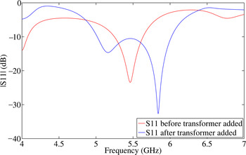
The slot array parameters (L 1 , L2, L4, L6, R, Wf, Ls , and W s ) were first optimized without the microstrip to slotline transition using a simple probe feed in the center of the array slotline feed structure. The aim of this optimization was to find an impedance response such that the microstrip to slotline transition could act as a bandwidth enhancing quarter wavelength transformer. The input impedance of the simplified array was adjusted to have a real impedance of 50 Ω in the center of the band, 75 Ω at the lower end, and 25 Ω at the upper end of the frequency band. The imaginary impedance was adjusted to have two in-band zero-crossings – one on either side of the center frequency. With the simplified geometry optimization complete, the microstrip to slotline transition was then added. The microstrip line length and width was then adjusted for optimal bandwidth. The subsequent improvement in impedance bandwidth is illustrated in Fig. 2. Once the array was optimized for impedance bandwidth, the radiation patterns were investigated to ensure they meet the required specifications.
The reflection coefficient of the 2 × 2 slot array before and after the addition of the microstrip to slotline transition (transformer).

C) A 2 × 2 printed planar slot array antenna
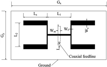
The most basic array of four elements shown in Fig. 3 was designed using the proposed procedure described above. The design was done for a Rogers RO4003 substrate with ε r = 3.38 and thickness t = 1.524 mm. The center frequency for the design was chosen as 5.5 GHz, and the bandwidth objective was to cover the entire 5.15–5.825 GHz operating band of the IEEE 802.11a standard. The array dimensions of the 2 × 2 array shown in Fig. 3 after the design optimization were L 1 = 16.5 mm, L 2 = 19.1 mm, L s = 19.6 mm, L m = 18.7 mm, W f = 0.5 mm, W m = 4.4 mm, W s = 6.0 mm, G x = 85.6 mm, and G y = 49.1 mm. The reflector ground plane dimensions were the same as the slot ground plane with G x = 85.6 mm and G y = 49.1 mm, positioned 13.6 mm (quarter wavelength at 5.5 GHz) below the slot array.
The 2 × 2 planar slot array antenna (shown without the reflector).

D) A 2 × 4 printed planar slot array antenna
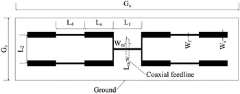
The substrate as well as center frequency and bandwidth design goals for the 2 × 4 array in Fig. 4 were the same as for the 2 × 2 array above. The array dimensions after the design optimization were L 1 = 13.9 mm, L 2 = 20.6 mm, L 4 = 16.1 mm, L s = 22.6 mm, L m = 19.9 mm, W f = 0.8 mm, W m = 5.4 mm, W s = 5.3 mm, G x = 160.0 mm, and G y = 45.0 mm. The reflector ground plane dimensions were the same as the slot ground plane with G x = 160.0 mm and G y = 45.0 mm, positioned 13.6 mm below the slot array.
The 2 × 4 planar slot array antenna (shown without the reflector).

E) A 4 × 2 printed planar slot array antenna
The array dimensions for the 4 × 2 array shown in Fig. 5 after the design optimization were L 1 = 15.2 mm, L 2 = 23.0 mm, L 3 = 19.5 mm, L 6 = 2.9 mm, R = 1.9 mm, L s = 22.6 mm, L m = 18.8 mm, W f = 0.5 mm, W m = 3.3 mm, W s = 4.6 mm, G x = 98.5 mm, and G y = 104.7 mm. The curved feedline path length was 39.7 mm. The reflector ground plane dimensions were the same as the slot ground plane with G x = 98.5 mm and G y = 104.7 mm, positioned 13.6 mm below the slot array.
The 4 × 2 planar slot array antenna (shown without the reflector).

III. ANTENNA PERFORMANCE EVALUATION
A) Experimental validation
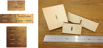
The three arrays were manufactured and measured. A photograph of the assembled arrays is shown in Fig. 6. The reflection coefficients were measured with a vector network analyzer, and the radiation properties were measured in the Compact Antenna Test Range of the University of Pretoria. The boresight gains of the arrays were measured in the 5–6 GHz frequency range by using a standard gain reference antenna and the well-known gain-transfer method. The principle plane radiation patterns (co- and cross-polarization) were measured at the center and the edges of the 5.15–5.825 GHz frequency band. The agreement between simulations and measurements were generally good – some of the differences (e.g. in the gain) can be attributed to the unwanted interaction between the antenna-under-test and the pedestal, mounting jig and feed cable used in the compact antenna range. A second cause of differences might be due to the variations because of slightly inaccurate assembly of the antennas.
Photographs of the printed planar arrays and the assembled slot arrays.

B) Reflection coefficient
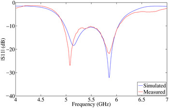
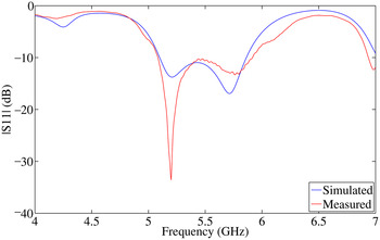
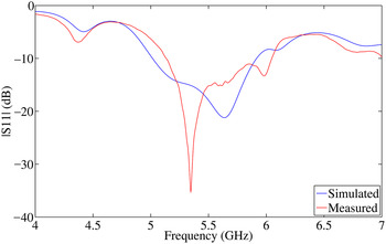
The simulated and measured reflection coefficients (S11) for the 2 × 2 array are shown in Fig. 7. The simulated and measured results for the 2 × 4 and 4 × 2 arrays follow in Figs 8 and 9. In general, there is good agreement between the simulated and measured results of all the arrays. The bandwidth of the measured arrays with a reflection coefficient below −10 dB for the 2 × 2 array was from 4.95 to 6.04 GHz, which is 19.8% relative to the center frequency of 5.5 GHz. The 2 × 4 array 10 dB bandwidth was from 5.08 to 5.92 GHz, which equates to 15.3%. For the 4 × 2 array, the −10 dB bandwidth was measured from 5.13 to 6.05 GHz, which is 16.7%.
Simulated and measured reflection coefficient of the 2 × 2 array.

Simulated and measured reflection coefficient of the 2 × 4 array.

Simulated and measured reflection coefficient of the 4 × 2 array.

C) Gain and aperture efficiency
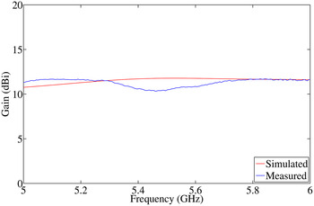
The simulated and measured boresight gain results are shown in Figs 10–12. In general, the simulated and measured gains compare well. The maximum gain of the manufactured 2 × 2 array, in the target band of 5.15–5.825 GHz, was measured as 11.7 dBi, with a minimum gain of 10.3 dBi. The maximum difference between the simulated and measured results was found to be 1.4 dBi at 5.46 GHz.
Simulated and measured gain versus frequency for the 2 × 2 array.

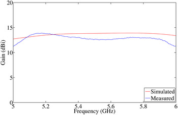
Simulated and measured gain versus frequency for the 2 × 4 array.

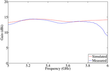
Simulated and measured gain versus frequency for the 4 × 2 array.

The maximum measured gain for the 2 × 4 array was 13.9 dBi and the minimum was 12.5 dBi. The maximum difference between the simulated and measured results was at 5.53 GHz, and equal to 1.3 dBi.
The 4 × 2 array also displayed good agreement between the simulated and measured results similar to the 2 × 2 and 2 × 4 arrays. The 4 × 2 array had a maximum measured gain of 14.4 dBi, and a minimum of 12.9 dBi. The maximum difference between the two sets of results was 0.8 dBi at 5.49 GHz.
The aperture efficiencies of the three arrays were calculated (using equations (1) and (2) in [Reference Ma and Vandenbosch9]) using the simulated gain – the data is shown in Fig. 13. The maximum radiation efficiencies were 86, 82, and 67%, for the 2 × 2, 2 × 4, and 4 × 2 array, respectively. It is interesting to note that the aperture efficiencies of the 2 × 2 and 2 × 4 arrays are significantly higher (above 75% for most of the frequency band) than that of the 4 × 2 array, and also significantly higher than the aperture efficiencies of typical wideband microstrip arrays, which are normally around 50–65% [Reference Ma and Vandenbosch9].
Aperture efficiency versus frequency for the three slot arrays.

D) Radiation patterns
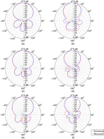
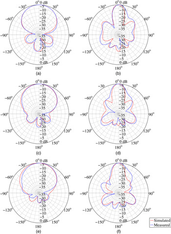
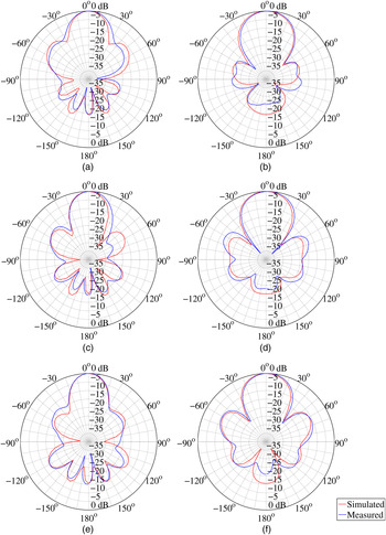
The normalized radiation patterns for the 2 × 2 array are shown in Fig. 14, the 2 × 4 array in Fig. 15, and the 4 × 2 array in Fig. 16. There is good agreement between the simulated and measured results. The worst sidelobe level measured was −10.5 dB for the 4 × 2 array in the H-plane at 5.825 GHz. Otherwise, the sidelobe levels are closer to −15 dB, and in many cases much better than −15 dB. The radiation patterns are relatively stable across the 5.15–5.825 GHz target bandwidth and are nearly symmetrical in both the E- and H-planes. The front-to-back ratios of all the arrays were also better than 15 dB.
Simulated and measured radiation patterns of the 2 × 2 array: (a) E-plane 5.15 GHz, (b) H-plane 5.15 GHz, (c) E-plane 5.5 GHz, (d) H-plane 5.5 GHz, (e) E-plane 5.825 GHz, and (f) H-plane 5.825 GHz.

Simulated and measured radiation patterns of the 2 × 4 array: (a) E-plane 5.15 GHz, (b) H-plane 5.15 GHz, (c) E-plane 5.5 GHz, (d) H-plane 5.5 GHz, (e) E-plane 5.825 GHz, and (f) H-plane 5.825 GHz.

Simulated and measured radiation patterns of the 4 × 2 array: (a) E-plane 5.15 GHz, (b) H-plane 5.15 GHz, (c) E-plane 5.5 GHz, (d) H-plane 5.5 GHz, (e) E-plane 5.825 GHz, and (f) H-plane 5.825 GHz.

The 3 dB beamwidths of the manufactured arrays were measured in the E- and H-planes at 5.15, 5.5, and 5.825 GHz. The beamwidth for each array remained stable across the entire frequency band of interest. The effect of narrowing the main beam in the E-plane with the addition of four additional slots by means of a vertical expansion of the 2 × 2 array is evident. Similarly, the 3 dB beamwidth of the 2 × 4 arrays is reduced from the original 2 × 2 array in the H-plane with the addition of additional slots in the horizontal plane. The 3 dB beamwidth at 5.5 GHz for the 2 × 2 array was 52.8° in the E-plane and 43.7° in the H-plane, for the 4 × 2 array it was 28.1° in the E-plane and 37.6° in the H-plane, and for the 2 × 4 array it was 57.0° in the E-plane and 21.2° in the H-plane.
The measured E-plane cross-polarization levels was better than −20.9 dB for all the arrays, and the measured H-plane levels better than −15 dB, accept for the 4 × 2 array at 5.5 GHz, which yielded a value of −11.7 dB.
IV. CONCLUSION
This paper shows how a simple design approach can be followed to design three easy to manufacture center-fed printed slot arrays for use as IEEE 802.11a WLAN antennas. The measured bandwidths of the three manufactured arrays exceeded the 12% bandwidth requirement. The 2 × 2 array achieved a maximum gain of more than 11 dBi, and the 2 × 4 and 4 × 2 arrays achieved maximum gains of around 14 dBi. In all cases the cross-polarization levels was low, the sidelobe levels were better than −10 dB, and the front-to-back ratios better than 15 dB. The aperture efficiencies of the 2 × 2 and 2 × 4 slot arrays were found to be significantly better than that of typical wideband microstrip arrays, and these slot arrays are therefore good candidates for applications where high gain is required but space is limited. The measured data of the manufactured arrays agree well with the simulated results.
 Llewellyn Potgieter received his B.Eng. and B.Eng. (Hons), and M.Eng. degrees in Electronic Engineering from the University of Pretoria, Pretoria, South Africa, in 2009 and 2011, respectively. From 2012 to 2014 he was employed as an Electronic Warfare Research Engineer at the Council for Scientific and Industrial Research, Pretoria. He joined Saab Grintek Defence in 2014 and is presently involved in various electronic warfare projects. His main research interests are antenna arrays and broadband antennas for electronic warfare applications.
 Johan Joubert received the B.Eng., M.Eng., and Ph.D. degrees in Electronic Engineering from the University of Pretoria, Pretoria, South Africa, in 1983, 1987, and 1991, respectively. From 1984 to 1988 he was employed as a Research Engineer at the Council for Scientific and Industrial Research, Pretoria. In 1988 he joined the Department of Electrical and Electronic Engineering at the University of Pretoria, where he is presently a Professor of Electromagnetism. From July to December 1995 he was a Visiting Scholar at California State University, Northridge, USA. From July to December 2001 he was a Visiting Scientist at Industrial Research Laboratories in Wellington, New Zealand. From July to December 2006 he was a Visiting Scholar at Universität Karlsruhe (TH), Germany, and from July to September 2010 he visited Loughborough University in the UK for a collaborative research project on metamaterials. His research interests include antenna array design and computational electromagnetism.
 Johann W. Odendaal received the B.Eng., M.Eng., and Ph.D. degrees in Electronic Engineering from the University of Pretoria, Pretoria, South Africa, in 1988, 1990, and 1993, respectively. From September 1993 to April 1994, he was a Visiting Scientist with the ElectroScience Laboratory at the Ohio State University. From August to December 2002, he was a Visiting Scientist with CSIRO Telecommunications and Industrial Physics in Australia. Since May 1994, he has been with the University of Pretoria, where he is presently a Full Professor. His research interests include electromagnetic scattering and radiation, compact range measurements, and signal processing. He is also Director of the Centre for Electromagnetism at the University of Pretoria. Professor Odendaal is a member of the Antenna Measurement Techniques Association (AMTA) and is registered as a Professional Engineer in South Africa.