1. Introduction
Visual recognition has made significant advancements in recent years, driven by the availability of large-scale datasets and increased computing power. However, passively analyzing visual information from datasets does not fully address the challenges encountered by real-world robots, which must actively acquire their own visual observations. Active perception of autonomous mobile robot addresses these challenges by developing task-specific motion policies, including point-goal navigation aiming to reach a specified coordinate within the environment [Reference Ye, Batra, Wijmans and Das1–Reference Zhou, Yi, Zhang, Chen, Yang, Han and Zhang3], object-goal navigation focusing on finding a specific object [Reference Chaplot, Gandhi, Gupta and Salakhutdinov4–Reference Zhou, Liu, Zhao and Liang7], image-goal navigation directing the robot to a location indicated by an image [Reference Chaplot, Salakhutdinov, Gupta and Gupta8], room-goal navigation directing the robot to a designated room [Reference Wu, Wu, Tamar, Russell, Gkioxari and Tian9].
In contrast, visual exploration [Reference Ramakrishnan, Jayaraman and Grauman10–Reference Bigazzi, Cornia, Cascianelli, Baraldi and Cucchiara12] is universal and task-agnostic, requiring a robot to systematically explore all navigable regions of an unknown environment with maximum efficiency. It can act as a precursor to more target-oriented tasks mentioned above. For example, a robot often begins by exploring an unfamiliar environment to gather essential environmental knowledge, enabling it to perform subsequent tasks more effectively. To date, many methods have been proposed for the visual exploration problem of autonomous mobile robot. Generally, these methods can be divided into two categories: heuristic methods [Reference Yamauchi13–Reference Liu, Wang, Chi, Chen and Sun16] and learning-based methods [Reference Pathak, Agrawal, Efros and Darrell17–Reference Khlif, Nahla and Safya25]. Recent approaches mainly focus on learning-based methods. To predict the optimal actions via visual information, these methods typically use deep reinforcement learning (DRL) with a multitude of exploration rewards, like curiosity reward [Reference Pathak, Agrawal, Efros and Darrell17, Reference Burda, Edwards, Pathak, Storkey, Darrell and Efros18], novelty reward [Reference Bellemare, Srinivasan, Ostrovski, Schaul, Saxton and Munos19, Reference Savinov, Raichuk, Marinier, Vincent, Pollefeys, Lillicrap and Gelly20], coverage reward [Reference Chen, Gupta and Gupta21], and reconstruction reward [Reference Jayaraman and Grauman22–Reference Seifi and Tuytelaars24].
However, in current visual exploration methods, the camera is firmly set to the robot’s body, limiting its relative orientation. In recent years, mobile robots with high freedom of movement, such as humanoid robots, have developed rapidly. Traditional visual exploration methods with fixed camera configurations greatly limit the robot’s initiative to explore the unknown environment. A fixed camera pose limits the robot’s field of view (FOV) to a forward-facing direction, restricting its ability to perceive the environment over a broader range. As shown in Figure 1 (a), the robot with fixed camera only observes limited environmental information as its camera orientation is always consistent with the movement direction. In contrast, we human beings can rotate our necks actively to observe more surrounding information when moving forward. Therefore, to enhance the robot’s flexibility in indoor exploration, it is necessary to make the robot adjust its “neck” (i.e., camera orientation) actively. Inspired by the above observations, we propose to incorporate a camera view planning (CVP) policy into visual exploration. In exploring unknown indoor environments, two policies are used, the path planning policy that decides where to go, and the CVP policy that decides the orientation of camera. The CVP policy can be used to obtain more environmental information by altering the orientation of camera actively. As shown in Figure 1 (b), the robot walks forward along the corridor. At position 1, it adjusts the orientation of camera to the right and discovers a new area. Then, the robot continues to walk forward while adjusting the orientation of camera to the front and discovers another new area ahead. Therefore, the exploration efficiency of the robot with active camera is higher than the robot with fixed camera. However, learning an effective CVP policy is non-trivial. Extracting meaningful information from complex RGB-D observations to determine the most promising directions for exploration is a challenging task.
Illustration of solving the indoor exploration problem. (a) The robot with fixed camera. (b) The robot with active camera.

In this paper, we propose a visual exploration method with the CVP policy to determine the actions of an active camera. Specifically, to help the robot better understand surrounding environment and its own location information to determine camera actions, we transform unstructured RGB-D observations to an egocentric spatial map that contains information about obstacles and room layouts by using a modified visual simultaneous localization and mapping (vSLAM) method. Each pixel in the map indicates whether the corresponding location is unexplored, free, or occupied. Besides, to avoid motion conflicts between the orientations of the body and camera, we consider body actions for the CVP policy according to the path planners. We then input three types of information, i.e., the progressively constructed spatial map, the visual observations, and the body action, into a CVP policy network to determine the appropriate camera action. A DRL algorithm is employed to train the network by carefully designing rewards considering exploration area, information acquisition efficiency, and motion conflict. Through comprehensive simulations and experiments in indoor environments, the effectiveness of the proposed method is demonstrated. The key contributions of this paper are outlined as follows:
-
1) Different from the existing forward-looking robots, we propose a new active perception paradigm, where the robot actively coordinates both camera and body actions to perceive the environment more effectively, thereby enhancing its ability to solve the visual exploration task of autonomous mobile robot.
-
2) We propose learning the CVP policy to decide camera actions using a carefully designed reward function, which considers factors such as exploration area, observed semantic objects, and the motion conflicts between the camera and the robot’s body. Such a CVP policy can be seamlessly integrated into the mainstream robot’s body exploration policy.
-
3) The effectiveness of the proposed method is demonstrated in the 3D physical simulation platform Habitat [Reference Savva, Kadian, Maksymets, Zhao, Wijmans, Jain, Straub, Liu, Koltun and Malik26] and a real-world indoor environment. More importantly, the CVP policy demonstrates strong transferability to unseen real environments.
2. Related work
2.1. Visual exploration
Visual exploration has attracted considerable attention because of its versatility and independence from specific tasks. Classical methods, such as frontier-based exploration (FBE) approaches [Reference Yamauchi13, Reference Holz, Basilico, Amigoni and Behnke27, Reference Dornhege and Kleiner28], utilize an occupancy map to calculate frontier points between explored and unexplored regions, and explore the environment based on heuristics (e.g., moving toward the nearest frontier). However, the safety of the next point is uncertain, as its distance from obstacles may be insufficient. González-Baños and Latombe [Reference González-Banos and Latombe29] defined safe areas for exploration and developed a Next-Best-View (NBV) algorithm to determine the optimal area for the robot to move toward. Generally, the core of the above classical methods is to identify the next optimal frontier point based on the current frontier point and the occupancy map. However, as the exploration area expands, the computational burden of solving this optimization problem grows rapidly.
The recent rise of DRL has sparked a new wave of advancements in visual exploration. Many studies treat visual exploration as a partially observable Markov decision process (POMDP) and tackle it within the RL framework. Existing methods mainly focus on designing novel rewards to improve performance. Specifically, Chen et al. [Reference Chen, Gupta and Gupta21] and Jayaraman and Grauman [Reference Jayaraman and Grauman22] used an end-to-end DRL strategy to maximize an extrinsic reward with respect to the explored area. Burda et al. [Reference Burda, Edwards, Pathak, Storkey, Darrell and Efros18] and Dean et al. [Reference Dean, Tulsiani and Gupta30] incorporated intrinsic rewards, such as curiosity, to promote efficient exploration, which shows improved performance when extrinsic rewards are sparse. To mitigate the sample complexity issue in end-to-end training, Chaplot et al. [Reference Chaplot, Gandhi, Gupta, Gupta and Salakhutdinov31], Ramakrishnan et al. [Reference Ramakrishnan, Al-Halah and Grauman32], Chen et al. [Reference Chen, Majumder, Al-Halah, Gao, Ramakrishnan and Grauman33], and Liu et al. [Reference Liu, Suganuma and Okatani34] inferred an exploration goal using a learned policy and utilized a path planner to navigate toward this goal. Niroui et al. [Reference Niroui, Zhang, Kashino and Nejat35] integrated a DRL-based point selection strategy into the FBE algorithm. The DRL policy network is trained using the Asynchronous Advantage Actor-Critic (A3C) algorithm, which has been shown to outperform multiple variants of the cost-utility FBE method. Predicting the occupancy of an unknown environment can offer valuable prior knowledge to aid exploration tasks. Shrestha et al. [Reference Shrestha, Tian, Feng, Tan and Vaughan36] predicted unknown areas of a partially explored map using a generative neural network and used these predictions to enhance the exploration process. Zwecher et al. [Reference Zwecher, Iceland, Levy, Hayoun, Gal and Barel37] integrated a map completion module to accelerate the indoor mapping process. Contrary to existing methods, we actively control the orientation of camera to mimic the human behavior of turning the neck to gain a wider FOV for a more efficient exploration of the environment.
2.2. Camera view planning
CVP can also be considered as an NBV problem, which seeks to determine the optimal view sequence for the camera and is a challenging problem in the field of active robot vision. One of the key applications of CVP is in reconstructing the 3D structure of real-world objects or scenes. Wu et al. [Reference Wu, Sun, Long, Huang, Cohen-Or, Gong, Deussen and Chen38] introduced a novel CVP algorithm for high-quality object reconstruction that visually evaluates each voxel within the voxel space to generate a view vector field (VVF), enabling the selection of the optimal view for the next scan. Mendoza et al. [Reference Mendoza, Vasquez-Gomez, Taud, Sucar and Reta39] proposed a 3D convolutional neural network (CNN) called NBV-Net, which effectively predicts the NBV using a classification method, achieving fast computation for reconstructing multiple unknown objects. The training data is generated based on the principle that the NBV should maximize the scanned surface while overlapping with the accumulated point cloud. Kaba et al. [Reference Kaba, Uzunbas and Lim40] proposed an RL approach to generate a sequence of viewpoints that can fully sense all the accessible area of a given object represented as a 3D model. The training objective is to minimize the number of required viewpoints. Chen et al. [Reference Chen, Liu, Zhang and He41] solved the full-view coverage problem of all target points in the scene with rotatable cameras.
Another application of CVP is object recognition. While object recognition from single-view images has been thoroughly explored, several practical challenges (e.g., occlusion, lighting, texture) complicate the process. CVP for object recognition can aid in locating key object features, thereby enhancing recognition accuracy and efficiency. Wu et al. [Reference Wu, Song, Khosla, Yu, Zhang, Tang and Xiao42] developed a convolutional deep belief network called ShapeNet to aid in view evaluation. When an object cannot be accurately identified, the recognition system can actively select the NBV to enhance the recognition rate. Johns et al. [Reference Johns, Leutenegger and Davison43] proposed a CNN-based approach that directly infers the NBV for object recognition. The network takes multiple images from different viewpoints as paired input and outputs a probability distribution that implicitly provides an entropy-based confidence measure.
In summary, CVP has found extensive application in fields such as object reconstruction, scene reconstruction, and object recognition. However, in the field of visual exploration of autonomous mobile robots, most methods still constrain the camera to the robot’s body, which deviates significantly from human behavior. It is well-established that when individuals enter an unfamiliar environment, their neck and eye movements coordinate with body motion to gather comprehensive information about their surroundings. Therefore, enabling independent camera rotation is crucial for enhancing the capabilities of visual exploration. In our previous work [Reference Dai, Meng, Jin and Liu44], a CVP policy learned by generative adversarial imitation learning is proposed to improve the efficiency of exploring unknown environments. However, a large number of expert demonstrations are used to train the CVP policy, which requires a very time-consuming collection process. This article casts the CVP policy as an RL problem, encouraging robots to increase the exploration area and observed semantic objects, and reduce the motion conflicts through the design of reward function, without the need for complex expert experience collection process.
3. Method
3.1. Overview
Given a robot with an RGB-D camera in an unknown environment, the visual exploration task requires the robot to efficiently visit all navigable areas in the shortest possible time. During this process, most existing methods design an exploration policy that analyzes visual observations from the environment and determines an appropriate body action
 $a^{b}$
(i.e., FORWARD, TURN-LEFT, and TURN-RIGHT). However, these approaches neglect the active adjustment of the camera’s orientation during movement. Consequently, the robot’s perception of the environment is constrained by its FOV, leading to low exploration efficiency.
To address the above problem, we propose a novel exploration paradigm that consists of a body exploration policy
 $\pi ^{b}(\! \cdot \!)$
and a CVP policy
 $\pi ^{c}(\! \cdot \!)$
, which are used to infer a body action
 $a^{b}$
and a camera action
 $a^{c}$
, respectively. We reformulate both body movement and camera movement as a POMDP, where the visual observations do not fully represent the state of the environment. At each time step, the body exploration policy first predicts a body action
 $a^{b}\sim \pi ^{b}(\! \cdot \!)$
for robot’s body movement, and then the CVP policy predicts a camera action
 $a^{c}\sim \pi ^{c}(\! \cdot \!)$
for active camera movement. The action space of
 $a^{b}$
is analogous to the navigation action space. The camera actions include {TURN-CAMERA-LEFT, TURN-CAMERA-RIGHT, KEEP}, where “KEEP” indicates that the camera direction remains fixed. Once the camera action is executed, the camera policy receives a reward r, the details of which are provided in Section 3.2. We refer to the robot that employs this paradigm as active-camera robot, and the overall framework is illustrated in Figure 2.
Overall framework of an active-camera robot for visual exploration. The exploration process involves two policies: the exploration-focused CVP policy, which decides where to look, and existing body exploration policy [Reference Chaplot, Gandhi, Gupta, Gupta and Salakhutdinov31], which decides where to move.

3.2. Learning to choose camera action
Learning a CVP policy to determine the camera’s orientation is challenging due to two main reasons: 1) the complexity of interpreting intricate room structures from RGB-D observations, and 2) the robot’s position is continuously changing, which necessitates coordination between camera movement and body movement. In this paper, we design an exploration-focused CVP policy comprising a mapper and a policy network. The mapper converts RGB-D observations into a top-down spatial map, providing a direct representation of the room layout and the locations of unexplored areas. The policy network then predicts the camera action based on the encoded features of the spatial map, visual observations, and body action, and provides information about the robot’s next position. Next, we describe each component in detail.
Conversion from the octree map and pose estimation to the local spatial map.

1) Mapper
A modified ORB-SLAM2 [Reference Mur-Artal and Tardós45] is used to build a spatial map. The modified ORB-SLAM2 takes RGB-D images as input and processes them sequentially. In addition to the tracking, local mapping, and loop closure threads in the original ORB-SLAM2, a new mapping thread is added. In the mapping thread, we first initialize a global spatial map
 $M^{g}$
of size 3 × L × W with values of zero. Specifically, the RGB-D images and estimated pose of each keyframe are used to generate a local 3D point cloud dense map. For any 2D pixel
 $[u,v]$
on the image, the corresponding 3D spatial point in the world coordinate system can be calculated using the following formula:
 \begin{equation} P_{w}=d_{uv}\cdot R_{wc}\cdot \left[\frac{u-c_{x}}{f_{x}},\frac{v-c_{y}}{f_{y}},1\right]^{T}+t_{wc} \end{equation}
where
 $c_{x} , c_{y} , f_{x}$
, and
 $f_{y}$
are the pre-calibrated camera parameters,
 $d_{uv}$
represents the depth of the pixel (i.e., the distance from the center of the camera to the 3D spatial point),
 $R_{wc}$
indicates the rotation matrix from the camera coordinate system to the world coordinate system,
 $t_{wc}=[t_{x},t_{y},t_{z}]^{T}\in \mathrm{\mathbb{R}}^{3}$
represents the translation vector. Therefore, a local 3D point cloud dense map can be generated by computing the 3D spatial point
 $P_{w}$
in the world coordinate system for each pixel in the keyframe. Subsequently, the local 3D point cloud dense map is converted to a local 3D octree map. The octree representation [Reference Hornung, Wurm, Bennewitz, Stachniss and Burgard46] offers advantages such as compressibility, flexibility, efficiency, and ease of updating.
Then, a top-down local spatial map
 $M_{t}^{l}$
is generated according to the local 3D octree map and pose estimation. To ensure the safety and efficiency of visual exploration, it is crucial to obtain three types of information: (1) whether an area has been explored, (2) whether an area contains obstacles, and (3) the locations previously visited by the robot. As illustrated in Figure 3, a local 3D space is represented using a local 3D octree map with the size of h × l × w, where h, l, and w are the preset height, length, and width of the map, respectively. The height of the local 3D octree map is obtained by avoiding interference from the ceiling and the ground, respectively. Each voxel of the local 3D octree map is divided into three categories: occupied, free, and unexplored. By projecting the local 3D octree map onto the 2D plane, the explored area map can be obtained, which reflects whether an area has been explored or not. The explored area map is represented by a binary map, where a value of 1 denotes that the corresponding area has been visited, and a value of 0 indicates that the corresponding area has not been explored. Then, the local 3D octree map is intercepted according to the robot’s height. The intercepted local 3D octree map incorporates the spatial area below the camera and above the ground. By projecting the intercepted local 3D octree map onto the 2D plane, the obstacle occupancy map can be obtained, which reflects whether an area has been occupied or not. The obstacle occupancy map is represented by a binary map, where a value of 1 denotes that the corresponding area has been occupied, and a value of 0 indicates that the corresponding area has not been occupied. Moreover, to help the robot better understand its own location information, we also add a channel to the map to represent the robot’s trajectory information. To align the robot’s trajectory with the two channels mentioned above, the estimated pose must be projected onto a 2D planar coordinate system. The projected pose estimation at step t can be computed as follows:
 \begin{equation} pose_{t}=\left[\frac{t_{x}}{\rho },\frac{t_{y}}{\rho },\arctan \left(\frac{R_{23}}{R_{13}}\right)\right]^{T} \end{equation}
where the first two terms represent the x and y coordinates of the camera, while the third term denotes the camera’s orientation in radians, measured counterclockwise from the x-axis. The constant
 $\rho$
represents the resolution, which is set to 5 cm in this paper. By applying Eq. (2) at all steps, a robot trajectory map can be generated. This map has the same size as the explored area map and the obstacle occupancy map. In the robot trajectory map, a value of 1 indicates that the corresponding area has been visited by the robot, whereas a value of 0 indicates that it has not. The explored area map, the obstacle occupancy map, and the robot trajectory map are then rotated according to the camera’s orientation, which aims at integrating the orientation information into the local spatial map. The above three rotated maps are combined into the local space map
 $M_{t}^{l}$
with a size of 3 × l × w. The three channels of the local space map correspond to the explored area map, the obstacle occupancy map, and the robot trajectory map. Finally, we integrate the local spatial map
 $M_{t}^{l}$
into the global spatial map
 $M_{t}^{g}$
.
2) Policy network
With the observation images and progressively built spatial map, we use a policy network to aggregate this information at each time step. The network takes the spatial map
 $M_{t}^{g}$
, the observation images
 $o_{t}$
, and the body action
 $a_{t}^{b}$
as input. The size of the global spatial map
 $M_{t}^{g}$
is 3 × L × W, where L = W = 256. The three-channel RGB image and the one-channel depth image are stacked together to form the input
 $o_{t}$
, which has the size of
 $4\times 256\times 256$
. The structure of the policy network is divided into three parts: the encoder and two Multi-Layer Perceptrons (MLPs). Specifically, in the encoder, two CNNs are utilized to extract map features and image features from
 $M_{t}^{g}$
and
 $o_{t}$
, respectively. Each CNN is made up of a five-layer fully convolutional layers. Another type of feature is encoded from
 $a_{t}^{b}$
by using fully connected layers. The above types of features are aggregated into one feature, which is further compressed through fully connected layers to acquire the current observed encoding feature
 $s_{t}$
. Then,
 $s_{t}$
is fed into two MLPs, one for predicting the camera action
 $a_{t}^{c}$
with the size of
 $1\times 3$
and the other for predicting the value of the camera’s current state.
3) Reward function
We aim for the camera policy to assist the robot in exploring the environment more effectively. This is achieved in two ways. On the one hand, we explicitly encourage the CVP policy to explore more areas and semantic objects. The regions of explored areas e can be obtained from the first channel of the constructed spatial map. Therefore, the exploration reward
 $r_{\exp }$
can be expressed as the increased exploration regions
 $e_{t}-e_{t-1}$
during the exploration process in successive time steps. Moreover, low-texture areas such as walls, floors, and ceilings are not conducive to information collection for robot exploration, and can easily lead to the tracking failure problem of vSLAM. Therefore, an object-level weighted semantic reward
 $r_{sem}$
is proposed to encourage the CVP policy to explore more semantic objects besides walls, floors, and ceilings. Considering that the observed semantic objects within the camera’s FOV are often incomplete, we approximate the object as a circle and use the central angle as the degree of observation. The specific calculation process is shown in Figure 4, where the angle
 $\varphi _{FOV}$
formed by yellow lines
 $l_{OF}$
and
 $l_{OV}$
represents the camera’s FOV, the yellow line
 $l_{OH}$
indicates the orientation of the camera, the pink and black lines denote the observed and unobserved parts of the object, respectively. The solid blue lines
 $l_{OA} , l_{OA'}$
, and
 $l_{OB}$
stand for the tangent lines of the observed parts. The center point of the object and the camera on the spatial map are defined as
 $O'$
and O, respectively. The intersection points of the tangent line and the circle are defined as A,
 $A'$
, and B. The solid blue lines
 $l_{O'A}$
,
 $l_{O'A'}$
, and
 $l_{O'B}$
connect the center point of the object and the intersection points. When the semantic object observed in the camera’s FOV is incomplete, the intersection point of the camera’s FOV
 $l_{OV}$
with the observed semantic object is defined as V. The solid blue line
 $l_{O'V}$
connects the center point of the object and the intersection point V. The blue dotted line
 $l_{O'O}$
connects
 $O'$
and O.
The degree to which an object is observed by the camera.

First, we can compute the Euclidean distance d between
 $O'$
and O, which can be computed as follows:
 \begin{equation} d=\sqrt{\left(O'\left(2\right)-O\left(2\right)\right)^{2}+\left(O'\left(1\right)-O\left(1\right)\right)^{2}} \end{equation}
where
 $O(1)$
and
 $O'(1)$
are the horizontal coordinates of points O and
 $O'$
on the spatial map, respectively.
 $O(2)$
and
 $O'(2)$
are the vertical coordinates of points O and
 $O'$
on the spatial map, respectively.
Then, for the object that is completely within the camera’s FOV, the degree to which the object is observed by the camera, denoted by
 $\omega$
, can be calculated as:
 \begin{equation} \omega =\varphi _{AO'A'}=2\arccos \left(R/d\right) \end{equation}
where
 $\varphi _{AO'A'}$
represents the angle formed by the lines
 $l_{O'A}$
and
 $l_{O'A'}$
. R is the radius of the object that is approximated as a circle.
For the object that is partially within the camera’s FOV, the degree
 $\omega$
can be calculated as follows:
 \begin{align} \omega & =\varphi _{BO'V}=\varphi _{BO'O}+\varphi _{OO'V} \nonumber \\[3pt] & =\arccos \left(\frac{R}{d}\right)+\pi -\varphi _{O'OV}-\varphi _{OVO'} \nonumber \\[3pt] & =\arccos \left(\frac{R}{d}\right)+\pi -\varphi _{O'OV}-\arcsin \left(\frac{d\sin \left(\varphi _{O'OV}\right)}{R}\right) \end{align}
where
 $\varphi _{BO'V}$
denotes the angle formed by the lines
 $l_{O'B}$
and
 $l_{O'V}$
.
 $\varphi _{BO'O}$
represents the angle formed by the lines
 $l_{O'B}$
and
 $l_{O'O}$
.
 $\varphi _{OO'V}$
indicates the angle formed by the lines
 $l_{O'V}$
and
 $l_{O'O}$
.
 $\varphi _{OVO'}$
means the angle formed by the lines
 $l_{OV}$
and
 $l_{O'V}$
.
 $\varphi _{O'OV}$
is the angle formed by the lines
 $l_{OV}$
and
 $l_{O'O}$
.
 $\varphi _{O'OV}$
can be further computed as follows:
 \begin{align} \varphi _{O'OV} & =0.5\varphi _{FoV}-\varphi _{O'OH} \nonumber \\[3pt] &=0.5\varphi _{FoV}-\arctan \left(\frac{O'\left(2\right)-O\left(2\right)}{O'\left(1\right)-O\left(1\right)}\right) \end{align}
where
 $\varphi _{O'OH}$
represents the angle formed by the lines
 $l_{OH}$
and
 $l_{O'O}$
.
Assuming that N objects are observed, the object-level weighted semantic reward
 $r_{sem}$
is defined as:
 \begin{equation} r_{sem}=\sum _{i=1}^{N}\omega _{i} \end{equation}
On the other hand, the camera rotation may lead to a problem of motion conflict between the camera and the robot’s body. Therefore, to avoid frequent motion conflicts and reduce energy consumption, we expect the robot’s body movement and the camera movement to be as consistent as possible. We define a motion conflict penalty reward
 $r_{con}$
, which is 0 when the robot body and the camera move in the same direction or slightly deviate.
 $r_{con}$
is 1 when the robot body and the camera take completely opposite actions.
To sum up, the reward function
 $r_{t}$
is the weighted sum of the above three parts, which is defined as:
 \begin{equation} r_{t}=r_{\exp }+\lambda _{1}\cdot r_{sem}-\lambda _{2}\cdot r_{con} \end{equation}
where
 $\lambda _{1}$
and
 $\lambda _{2}$
represent the hyper-parameters.
4) Training process
In this paper, we use a policy gradient algorithm: Proximal Policy Optimization (PPO) [Reference Schulman, Wolski, Dhariwal, Radford and Klimov47] to update the policy network of the proposed CVP policy. The actor consists of the encoder and one MLP with parameters denoted by
 $\xi _{A}$
. The critic consists of the encoder and another MLP with parameters denoted by
 $\xi _{C}$
. Let
 $r(\xi _{A})$
be the probability ratio between the new actor with parameters
 $\xi _{A}$
and the old actor policy with parameters
 $\xi '_{A}$
during the training iteration. To avoid excessive change between the new and old policies,
 $r(\xi _{A})$
is constrained to the range of
 $[1-\varepsilon ,1+\varepsilon ]$
via the clip term, where
 $\varepsilon$
is set to be 0.2 in this paper. Let
 $R_{{\xi _{A}}}=\sum _{i=t}^{T}\gamma ^{i-t}\cdot r_{i}$
be the expected reward and
 $\hat{v}_{{\xi '_{C}}}$
be the output of the old critic. The actor is expected to maximize the benefits of output actions during the update process, which is defined as:
 \begin{equation} J_{\textit{actor}}\left(\xi _{A}\right)=\min \left(r\left(\xi _{A}\right)\cdot A,clip\left(r\left(\xi _{A}\right),1-\varepsilon ,1+\varepsilon \right)\cdot A\right) \end{equation}
where
 $A=R_{{\xi _{A}}}-\hat{v}_{{\xi '_{C}}}$
is the advantage function.
Training method for the CVP policy

The optimization objective of the critic is defined as:
 \begin{equation} J_{\textit{critic}}\left(\xi _{C}\right)=\max \left(\begin{array}{l} MSE\left(\hat{v}_{{\xi _{C}}},R_{{\xi _{A}}}\right),\\[5pt] MSE\left(R_{{\xi _{A}}},\hat{v}_{{\xi '_{C}}}+clip\left(\hat{v}_{{\xi _{C}}}-\hat{v}_{{\xi '_{C}}},-\varepsilon ,\varepsilon \right)\right) \end{array}\right) \end{equation}
where
 $MSE(\! \cdot \!)$
represents the mean square error.
 $\hat{v}_{{\xi _{C}}}$
represents the output of the new critic. Similarly, to avoid the strategy iteration being too fast after importance sampling, clip function is also used.
The optimization objective of the policy network is defined as:
 \begin{equation} J\left(\xi _{A},\xi _{C}\right)=J_{\textit{actor}}\left(\xi _{A}\right)+\alpha \cdot J_{\textit{critic}}\left(\xi _{C}\right) \end{equation}
where
 $\alpha$
is a pre-defined parameter.
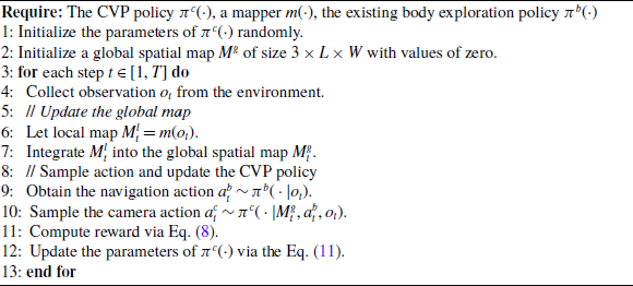
The complete training procedure of the proposed CVP policy is provided in Algorithm 1.
5) Combination of exploration policy and CVP policy
We employ the existing body exploration policy, active neural SLAM (ANS) [Reference Chaplot, Gandhi, Gupta, Gupta and Salakhutdinov31], to infer a body action, which is then fed to the proposed CVP policy to infer a camera action. The body exploration policy selects the navigation action by utilizing a spatial map that is progressively built from the historical outputs of the CVP policy. The camera is mounted on a mobile robot platform via a gimbal. The robot moves to a specified position using omnidirectional wheels, while the camera’s orientation is adjusted by its motors. The rotation angles of both the robot body and the camera are synchronized. Therefore, when both are required to move in the same direction, only the robot’s wheels need to be turned, without the need to adjust the camera’s orientation.
4. Experiment
4.1. Experimental setup
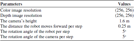
The CVP policy is trained on the open-source robot simulation platform Habitat [Reference Savva, Kadian, Maksymets, Zhao, Wijmans, Jain, Straub, Liu, Koltun and Malik26], where the robot can exist in physical form and perform real-time motion control. The dataset is from MatterPort3D [Reference Chang, Dai, Funkhouser, Halber, Niessner, Savva, Song, Zeng and Zhang48], which includes various scenes such as offices, living rooms, churches, etc. It contains environmental semantic information with 40 semantic categories. The training set contains 25 scenarios. Each scenario was trained 100 times from different starting points. The test set contains 9 scenes. Each scenario was tested 20 times with different starting points, with a total of 500 steps performed for each test. The parameter settings of the simulation environment are shown in Table I.
Parameter settings of the simulation environment.

4.2. Implementation details
The training optimizer was Adam. The discount factor
 $\gamma$
and the clip factor
 $\varepsilon$
were set to 0.99 and 0.2, respectively. Due to the actual physical meaning of the exploration area being measured in square meters, according to the pre-training results, the increased exploration area at each time step does not exceed 0.05 m2. The hyper-parameters
 $\lambda _{1}$
and
 $\lambda _{2}$
of the reward function were set to be 0.002 and 0.5, respectively. The used computer is equipped with an Intel Core i9-10900X CPU, 64 GB of memory, and an NVIDIA RTX 3090 GPU.
4.3. Evaluations in simulation environments
The proposed CVP policy combined with ANS method (ANS + CVP policy) was compared with the original ANS method and a random CVP policy combined with ANS method (ANS + Random policy). ANS method is a current mainstream visual exploration method. However, in ANS method, the camera cannot rotate independently, keeping the orientation consistent with the moving direction of the robot. In this paper, additional degrees of freedom have been introduced to the robot. We need to figure out whether the changes in performance are solely from expanding the degrees of freedom. Therefore, the “ANS + Random policy” method also needs to be compared in this paper. Moreover, to prove the effectiveness of the motion conflict penalty reward, we compared the proposed “ANS + CVP policy” method with “ANS + CVP policy (w/o penalty reward)” method. In the following, we will abbreviate the proposed “ANS + CVP policy” method as “Ours” for short, and the “ANS + CVP policy (w/o penalty reward)” method as “Ours (w/o penalty reward)” for short.
The representative visualization results of exploration areas of the above four methods are shown in Figure 5. It is noted that due to the different areas observed by the camera in different methods, the robot’s moving trajectories planned by the body exploration policies are also different. The visualization results show that the proposed method explores the environment more efficiently with the largest exploration area. Moreover, using the random policy brings almost no improvement and even has a negative impact. This is not surprising since coordinating camera and body actions is non-trivial. In addition, a larger action space may increase the difficulty of training. These results further highlight the significance of the proposed CVP policy in selecting appropriate camera actions. The route of the “Ours (w/o penalty reward)” method has multiple straight lines and multiple sharp turning points, which is caused by the inconsistency between path planning and CVP. When the camera motion and the robot motion are opposite, the robot does not move effectively. The motion conflict between them continues until the short-term goal given by the path planning module is substantially updated. This kind of update often has a big change in the direction. At this time, the body will turn and reposition several times before moving forward, resulting in a larger turn in place.
The visualization results of exploration areas of different methods. Note that the explored free areas, the explored occupied areas, and the unexplored areas are shown in white, green, and gray, respectively. The robot’s moving trajectory is illustrated in red.

Figure 6 compares the changes in the explored area and the average explored area per environment of the above three methods during the testing process. Figure 6(a) shows the change in the average explored area of all test scenes as the number of exploration steps increases. Our method and the “Ours (w/o penalty reward)” method can achieve a higher exploration area than the other methods under the same exploration step. This is because the camera can move freely and obtain more effective information in a limited number of steps through active observation in an unknown environment. ANS method without active camera always suffers from the over-coupling between the camera motion and the body motion, resulting in low robot exploration efficiency. Using random policy often results in large differences between adjacent frames observed by the camera, disrupting the performance of mapper. Figure 6(b) shows the average exploration area of the robot after walking 500 steps using three different exploration methods in 9 test scenes. In almost all scenes, our method outperforms the other methods. The average exploration area of our method is 38.34 m2, which is 8.79%, 11.68% and 24.49% larger than 34.97 m2 of “Ours (w/o penalty reward)” method, 33.86 m2 of ANS, and 28.95 m2 of the “ANS + Random policy” method, respectively.
Comparison of the explored area during the testing process in simulation environments. (a) Changes in average explored area. (b) Average explored area per environment.

Figure 7 compares the number of motion conflicts for the two kinds of CVP policies with and without motion conflict penalty reward
 $r_{con}$
. The number of motion conflicts for both methods increased with the number of exploration steps. The method with motion conflict penalty reward had a motion conflict every 13.4 steps on average, while the method without motion conflict penalty reward had a motion conflict every 5.8 steps on average. It shows that adding the motion conflict penalty reward can effectively reduce the frequency of motion conflicts between the camera and the robot’s body.
Comparison of the number of motion conflicts during the testing process in simulation environments. (a) Changes in the number of motion conflicts. (b) The number of motion conflicts per test scene.

4.4. Evaluations in real-world indoor environments
In this section, we evaluated the transferability of the learned CVP policy in real-world indoor environments. We integrated the proposed method with ROS (robot operating system) and qualitatively demonstrated it on a self-made differential wheeled robot platform (Figure 8(a)) with a rotatable RGB-D camera Astra Pro in real-world indoor environments (Figure 8(b) and Figure 8(c)). We conducted experiments in a small-scale indoor scene with few structured obstacles (Figure 8(b)) and a large-scale indoor scene with cluttered obstacles (Figure 8(c)). The small-scale indoor environment is a cubic room of size
 $9\, \mathrm{m}\times 9\, \mathrm{m}\times 4\, \mathrm{m}$
, with an Opti-Track motion capture system produced by NaturalPoint INC installed in the ceiling area. Three of the four sides of the scene were surrounded by 0.8 m high low-textured baffles. There were 4 obstacles placed regularly in the scene with the size of
 $0.3\, \mathrm{m}\times 0.3\, \mathrm{m}\times 1.2\, \mathrm{m}$
, and the distance between two obstacles was fixed at 0.5 m. The large-scale indoor scene with cluttered obstacles occupies a large area with no surrounding baffles. This environment is cluttered with cube obstacles, chairs, tables, whiteboards, and other objects.
Our robot platform and real-world indoor experimental environments.

The overall architecture of the robot platform system.

The robot platform system is composed of a remote service layer, an operating layer, and a driving layer. The overall architecture of the robot platform system is shown in Figure 9. The primary function of the server layer is to monitor the map information and infer the body actions and camera actions based on the visual observations from the environment. This layer employed a Lenovo laptop. The configurations of this laptop are as follows: OS: Ubuntu 18.04 (64 bit), CPU: i7-11800H, GPU: NVIDIA RTX 3080. The processing speed of the overall visual exploration framework can reach 5–8 Hz. The operating layer serves two primary functions: First, it receives instructions from the remote PC and transmits RGB-D observations from the camera to the remote PC based on WiFi signal emitted by the robot platform. Second, it processes feedback from the driver layer, oversees the motion control of the mobile robot, and continuously monitors its current state. The driver layer manages the control of the motors of the robot and gimbal, regulating their speed and position via pulse signal generation. Motor control is implemented using the STM32F103ZET6 microcontroller, selected for its robustness and extensive peripheral interface support. Programming is mainly done in C language.
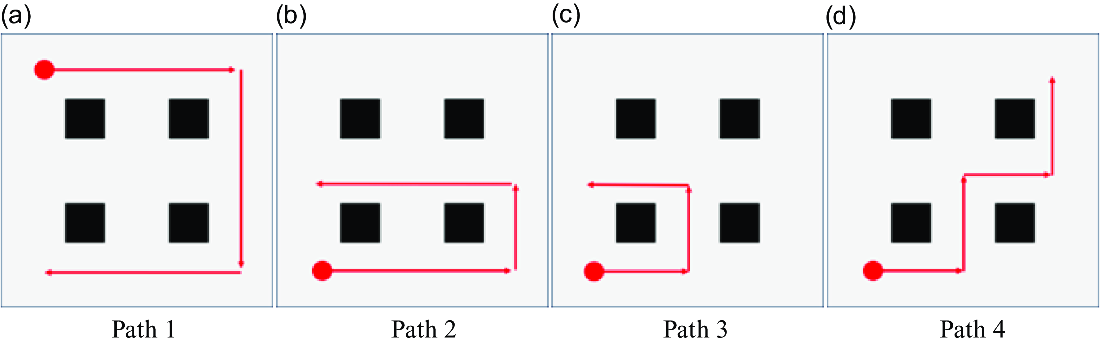
The designed paths are shown in Figure 10, where the red dots are the starting points of the robot. We compared the final exploration area, the average number of semantic objects observed per step, and the localization accuracy.
RTE performance index comparison (m).

RRE performance index comparison (
 $^{\circ}/m$
).

The designed movement paths of the robot. Note that the unoccupied areas and the occupied areas are shown in white and black, respectively. The robot’s moving trajectory is illustrated in red. The red dot indicates the robot’s starting point.

During the robot’s motion, two different estimation sets of the robot’s pose are obtained using the ANS method and our method, respectively. These estimation results are then compared against the ground-truth trajectory recorded by the Opti-Track motion capture system. The widely used metrics, relative translation error (RTE) and relative rotation error (RRE), were used in evaluations. Root mean square error (RMSE) was adopted to measure the RTE and RRE. As shown in Tables II and III, the existing body exploration policy, ANS, performs poorly in low-textured scenes due to an insufficient number of 2D feature points for reliable pose estimation. In contrast, the proposed method actively controls the camera’s orientation, resulting in a greater number of associated landmarks. Consequently, the proposed method can enhance the localization accuracy.
The average number of semantic objects observed per step for ANS and our method is shown in Table IV. Compared with ANS, the average number of semantic objects observed per step of our method is increased by about 11.62%. It means that the robot can observe more meaningful objects by incorporating the CVP policy, which is also conducive to improving the localization accuracy.
The comparison results of the exploration regions are shown in Table V. In Path 1, Path 2, and Path 3, where the robot moves along a long-distance route parallel to obstacles, the exploration area of our method significantly exceeds those of ANS. In Path 4, the exploration area of our method is slightly larger than ANS. This is because the robot frequently turns, which allows it to explore a large area even without the CVP policy. Compared with ANS, the average exploration areas of our method are increased by about 21.72%. It shows that the exploration efficiency is higher by incorporating the CVP policy. It is worth noting that the CVP policy is trained in simulation environments and has not been fine-tuned in a real-world indoor scene. There are significant differences between simulation and real-world indoor environments in scene style and layout distribution. The consistent improvement indicates that our active camera with the proposed CVP policy has successfully learned general exploration skills for indoor visual exploration tasks. Moreover, it demonstrates the possibility of transferring the robot with active camera to more real-world scenes.
Comparison of the average number of semantic objects observed per step in the small-scale indoor scene with few structured obstacles.

Comparison of explored area (
 $m^{2}$
) in the small-scale indoor scene with few structured obstacles.

Comparison of the average number of semantic objects observed per step in the large-scale indoor scene with highly cluttered obstacles.

The visualization results of 3D point cloud dense maps and explored areas of ANS and our method are shown in Figures 11 and 12, respectively. The explored free areas, the explored occupied areas, and the unexplored areas are shown in white, black, and gray, respectively. It is worth noting that due to the presence of many inaccurate depth values and depth values beyond the RGB-D camera’s range, many point clouds are removed as noise during the mapping process. Therefore, there are many holes in the final maps. From Figures 11 and 12, it can be found that the exploration areas of our method significantly exceed that of ANS. For example, in Path 1, our method can explore more areas. Especially in the areas indicated by the blue circle, our method can explore more comprehensively. This is because our method can not only observe the visual information in the direction of the robot’s movement, but also actively control the camera to observe more areas. In Path 2, the robot starts from the lower left corner of the scene. In ANS, the robot only receives the body actions output by the body exploration policy and can only observe the areas in front of the robot’s movement. By using the CVP policy, the camera actively explores more areas indicated by the red circle. In Path 3, our method explores the lower left area shown in the yellow circle more carefully. In Path 4, the areas indicated by the green circle are observed more comprehensively in our method. The above results further prove that the robot can explore the unknown indoor environments more efficiently by incorporating the CVP policy.
The visualization results of 3D point cloud dense maps and explored areas produced by the ANS method in the small-scale indoor scene with few structured obstacles. Note that the unoccupied areas and the occupied areas are shown in white and black in explored areas, respectively.

The visualization results of 3D point cloud dense maps and explored areas produced by our method in the small-scale indoor scene with few structured obstacles. Note that the unoccupied areas and the occupied areas are shown in white and black in explored areas, respectively.

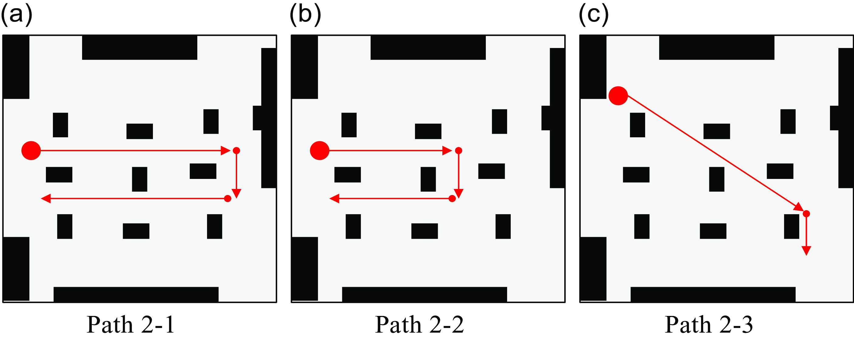
In order to verify the adaptability of our method, we conducted experiments in a large-scale indoor scene with cluttered obstacles. The designed movement paths of the robot in this scene are shown in Figure 13. We compared the final exploration area and the average number of semantic objects observed per step of ANS and our method under each designed path.
The average number of semantic objects observed per step for ANS and our method in the large-scale indoor scene with cluttered obstacles are shown in Table VI. Compared with ANS, the average number of semantic objects observed per step of our method is increased by about 9.14%. It means that more meaningful objects can be observed by incorporating the CVP policy, which will be beneficial to improving the localization accuracy and observation area.
The comparison results of the exploration regions are shown in Table VII. In all paths, the exploration area of our method exceeds that of ANS. Compared with ANS, the average exploration area of our method increases by about 25.6% on average, which shows a higher exploration efficiency than in the small-scale indoor scene with few structured obstacles. It is worth noting that after adding the CVP policy, the exploration area increases by up to 30.75% (path 2-3). This is because in path 2-3, the robot mainly walks in a straight line. Using the ANS method, the robot can only observe the area in the direction it is heading. After adding the CVP policy, the robot can explore more areas by actively adjusting the camera’s orientation during movement.
Comparison of explored area (m2) in the large-scale indoor scene with cluttered obstacles.

The designed movement paths of the robot in the large-scale indoor scene with cluttered obstacles. Note that the unoccupied areas and the occupied areas are shown in white and black, respectively. The robot’s moving trajectory is illustrated in red. The red dot indicates the robot’s starting point.

The visualization results of the explored areas produced by the ANS method in the large-scale indoor scene with cluttered obstacles. Note that the unoccupied areas and the occupied areas are shown in white and black, respectively.

The visualization results of the explored areas produced by our method in the large-scale indoor scene with cluttered obstacles. Note that the unoccupied areas and the occupied areas are shown in white and black, respectively.

The visualization results of explored areas of ANS and our method in the large-scale indoor scene with cluttered obstacles are shown in Figures 14 and 15, respectively. The explored free areas, the explored occupied areas, and the unexplored areas are shown in white, black, and gray, respectively. It is worth noting that due to inaccurate depth values and depth values beyond the range of the RGB-D camera, many point clouds were removed as noise during the mapping process, resulting in a large number of holes in the explored areas. From Figures 14 and 15, it can be found that the exploration areas of our method significantly exceed those of ANS. In ANS, the robot receives only the body actions generated by the body exploration policy and is limited to observing the areas directly in front of its movement. In contrast, our method enables the camera to actively explore a broader range of areas. The above results further demonstrate that incorporating the CVP policy enables the robot to explore unknown indoor environments more efficiently in large-scale scenes with cluttered obstacles.
5. Conclusion
To address the problem of incoordination between the camera and body of the existing robot, we propose a new visual exploration paradigm in which the robot can actively move the camera to perceive the environment more effectively. This active perception capability is very important for autonomous exploration in unknown environments. To determine the camera actions, we train a CVP policy using DRL, rewarding it for exploring larger areas, observing more semantic objects, and reducing motion conflicts between camera rotation and body movements. The proposed CVP policy can be integrated with the existing body exploration policy. Simulation and experimental results in indoor environments show that the exploration areas have been greatly enlarged by incorporating our CVP policy. Future research directions include the following points. First, incorporating some memory modules, such as recurrent convolutional networks (RNNs), into the network architecture to endow the robot with the ability to have long-term memories [Reference Zeng, Chang, Xie, Liu, Bai, Pan, Xu and Wei49]. Second, we plan to use multiple sensors, such as IMU and LiDAR, to improve mapping accuracy. Third, we aim to further improve the generalization capabilities of the CVP policy in dynamic environments.
Acknowledgments
The authors extend their gratitude to Dr. Xuyang Dai for his many research suggestions on this paper.
Author contributions
This study was jointly designed by the authors – Sheng Jin and Hao-Yu Wang. Sheng Jin and Hao-Yu Wang conducted the data collection, development, and experiments, while Chen-Yang Zhang and Shuai-Dong Yang participated in the evaluation. The article was written and organized by Sheng Jin and Shuai-Dong Yang under the guidance of Qing-Hao Meng.
Financial support
This research was supported in part by the National Natural Science Foundation of China under Grant numbers 62203321 and 42401533; in part by the China Postdoctoral Science Foundation under Grant number 2023M741702; in part by the Research Project of Basic Science (Natural Science) Research in Jiangsu Universities under Grant number 24KJB420002; and in part by the National Project Pre-research Project of Suzhou City University under Grant number 2024SGY020.
Competing interests
The authors declare no competing interests exist.
Ethical approval
None.