Introduction
In recent years, radio frequency identification (RFID) has drawn considerable attention to several commercial applications due to their compact circular polarization characteristics, such as vehicle security, electronic toll collection, access control, asset identification, industrial and manufacturing, etc. [Reference Finkenzeller1]. Many frequency bands have been designated to RFID systems, such as ultra-high frequency (UHF) and industrial scientific-medical (ISM) bands. International Telecommunication Union and Radio communication Sector (ITU-R) have defined an ISM 2.45 GHz band. The overall size of the readers and tags depends on the antenna size. Usually, tag antennas are linearly polarized, and the reader antenna needs to be circularly polarized (CP) to make it insensitive to the tag orientation. Therefore, it instigates researchers to design circularly polarized and miniaturized antennas for RFID handheld readers. In [Reference Tang and He2], a pair of T and U slots in a square patch is used to avoid the requirement of shorting pins to reduce the antenna size and to have broadband radiation. The CP radiation and reduction in antenna size are achieved by etching asymmetric slits in the four diagonals of the square patch [Reference Nasimuddin, Qing and Chen3]. A handheld reader at 2.4 GHz band is designed by using a slotted patch, two shorting strips, and a shorting wall [Reference Liu, Weng and Yang4]. In [Reference Nguyen, Paulson and Riley5], a combination of slits and slots are used to successfully reduce the size of the patch for the ISM RFID band that can be used in wireless sensors, personal area networking, and short-range data communications. An impedance matching and symmetrical broadside radiation is achieved by using the S-shaped impedance-matching network that fed the dual-stacked patches via a probe in [Reference Wu, Su, Gan, Chen, Huang and Zhang6]. In [Reference Sharma, Gautam and Kanaujia7], an arc-shaped strip is used to generate two orthogonal degenerated modes to achieve circular polarization, which is an essential requirement of the RFID band. An L-shaped plate is used to miniaturize the size of designed antenna for RFID application [Reference Lu and Liou8]. In [Reference Gautam, Farhan, Agrawal and Rambabu9], truncation of corners and eight slots in the four directions and one at the center of the square-shaped radiator are used to get circular polarization and size reduction, respectively. A coplanar waveguide (CPW)-fed antenna with circular slots incorporated into the ground plane was used to cover the wide RFID frequency band in [Reference Cao and Yu10] and a Wilkinson feed structure was used to generate wider 3 dB bandwidth in [Reference Sun and Wu11]. In [Reference Chen, Tsai, Sim and Kuo12], a loop tag antenna was proposed to cover the UHF RFID band with CP radiation. The Meandered-loop technique was used to miniaturize the size of the antenna in [Reference Chen, Sim, Tsai and Kuo13]. Furthermore, the authors in [Reference Li, Lu and Zhu14] used a planar self-balanced magnetic dipole technique and the authors in [Reference Lerkbangplad, Namahoot, Akkaraekthalin and Chalermwisutkul15] described a planar inverted-F antenna technique to achieve RFID application band. A concept of the meander strip line in [Reference Lu and Chang16] is used to improve axial ratio bandwidth. In [Reference Bajaj, Upadhyay, Kumar and Kanaujia17], researchers used a dipole technique to achieve RFID band. It is clearly evident from the data listed in Table 1 that the proposed antenna has the smallest size, larger beamwidth, more significant impedance, and the axial ratio bandwidth.
Performance comparison of the similar antennas

In this work, a rectangular patch with an F-shaped slot and one L-shaped slot coupled with CPW-fed rectangular ground plane with slots is introduced to operate at RFID 2.45 GHz band for mobile handheld reader application. The concept of slots loaded parasitic elements printed underneath a CPW-fed radiator is used to achieve the circular polarized radiation and size reduction in the proposed design. The design consists of a parasitic element loaded with F-slot and L-slot and a window-type slotted ground plane. The concept is validated by fabricating the designed antenna with the smallest size of 16.5 × 14.8 × 1.6 mm3 on FR4 material and measured in the anechoic chamber. Experimental results confirmed that the designed antenna offers a wider 10 dB impedance bandwidth and wider 3 dB axial ratio bandwidth. The operating principle of the antenna is explained using electric field distribution as explained in Section “Antenna design.” The parametrization and experimental outcomes are discussed in Sections “Parametric studies” and “Experimental outcomes and discussion,” respectively. In Section “Conclusion” the design is summarized. The optimized parameters of the proposed antenna are finally obtained using Computer Simulation Technology (CST) Microwave Studio (MWS).
Antenna design
Figure 1 illustrates the proposed structure with detailed parameters of the antenna. The proposed antenna is designed on a single layer FR04 substrate with a thickness of 1.6 mm, the relative permittivity of 4.4, and loss tangent of 0.02. This antenna consists of a window-type ground plane and a rectangular microstrip radiator on the same side on the dielectric material to provide coplanar waveguide feed. The miniaturization, CP radiation, and impedance matching are achieved by printing a T-shaped parasitic patch slotted with one F-shape slot and one L-shape slot on the other side of the dielectric material. This parasitic patch was excited through the electromagnetic coupling of the main driven structure of the antenna on the other side of the dielectric material.
Schematic design of the proposed antenna: (a) side view, (b) top view, and (c) bottom view.

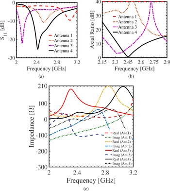
In the proposed antenna structure, various slot dimensions and shapes can be used to tune the input impedance of the antenna, including the real and imaginary parts at the desired frequency. At the outset, antenna-1 shown in Fig. 2(a) is used, but it excites at frequency 3.06 GHz with linear polarization (Table 2), as seen in Figs 3(a) and 3(b). In addition, the proposed design consists of coupling components between window-type ground plane and parasitic elements underneath of ground plane. Therefore, the tuning range of antenna-2 becomes narrower (see Fig. 3(a)) because the effective capacitance becomes higher than antenna-1 (see Fig. 3(c)) and unable to achieve circular polarization, as shown in Fig. 3(b). Similarly, the resonance frequency of antenna-3 becomes lower (see Fig. 3(a)) because the equivalent capacitance becomes higher than antenna-2 (see Fig. 3(c)) with improved CP radiation, as shown in Fig. 3(b). Further, the operating frequency of the proposed antenna (antenna-4) becomes higher than antenna-3 (see Fig. 3(a)) because the effective capacitance becomes lower than antenna-3 (see Fig. 3(c)) due to the reduced patch size, and dimensions of different slots are optimized to have a better CP radiation as shown in Fig. 3(b).
Evolution of the antenna design: (a) antenna 1, (b) antenna 2, (c) antenna 3, and (d) antenna 4.

Evolution of the proposed antenna: (a) simulated S 11, (b) simulated axial ratio, and (c) real and imaginary input impedances.

Detailed parametric dimensions marked in Fig. 1(b)

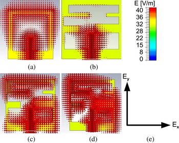
Figure 4 reveals the E-field distribution at 2.45 GHz frequency. Figures 4(a) and 4(b) show that the E-field distribution on antenna-1 and antenna-2 remained non-rotational type, which persists the linear polarization. However, Fig. 4(c) illustrates the E-field distribution on antenna-3 with unequal E-field components along the x-axis and y-axis. Figure 4(d) shows the rotation of distributed E-field vectors on antenna-4 was due to the occurrence of the two orthogonal E-field components along the x-axis and y-axis with equal amplitude (see Fig. 4(e)), consequently resultant E-field vectors are oriented at around 45° with respect to the y-axis.
Distributed E-field at 2.45 GHz for (a) antenna 1, (b) antenna 2, (c) antenna 3, (d) antenna 4, (e) and process for the genesis of orthogonal E-field components.

Circular polarization mechanism
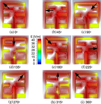
Usually, CP radiation can be excited by generating two electric field components with quadrature phase difference and equal amplitude [Reference Agrawal, Gautam and Rambabu18]. The simulated electric field distributions on the parasitic loaded patch antenna at different time phases are investigated as time instant increases from wt = 0° to wt = 360°, as illustrated in Fig. 5. At wt = 0°, the two components of electric field wave radiate in −x and −y directions, respectively. Consequently, the resultant electric field radiation makes a 45° from the −y direction (see Fig. 5(a)). At the next time instant the electric field radiation is in the −x direction, because the electric field radiation on the top flow in the opposite directions (i.e. −y and +y directions), canceling the radiation obtained by each other as shown in Fig. 5(b). Further, at later time instants, the electric field rotates anti-clockwise direction to yield the right-handed circularly polarized (RHCP) radiation at 2.45 GHz.
Distributed E-field at center frequency of 2.45 GHz for different times from wt = 0° to wt = 360°.

Design strategy
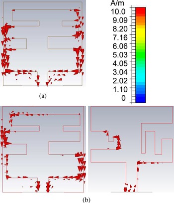
The bottom side parasitic patch and top side ground plane deployed with slots are used for radiation of surface current at 2.45 GHz RFID band. The surface current of antenna-2 (see Fig. 2), as shown in Fig. 6(a), at 2.45 GHz appears to flow only in the −y direction, while there is no surface current in the x-direction. So, it fails to achieve CP radiation. On the other hand, after incorporating a parasitic radiator underneath the ground plane, the surface current of antenna-4 (see Fig. 2) is depicted in Fig 6(b). The surface current at 2.45 GHz appears to flow in the −y direction as well as in the −x direction with equal amplitude. It, therefore, creates two orthogonal degenerated modes. Consequently, a good quality CP radiation is achieved at 2.45 GHz.
Simulated surface current distribution (a) at 2.45 GHz for antenna-2 and (b) at 2.45 GHz for the proposed design.

Parametric studies
The performance of the designed antenna was also investigated by altering the one parameter, and others kept constant. The simulated results were calculated, studied, and presented in this section.
Variation of window-type slot horizontal length in top side ground plane W 3
The effect of the width W 3 (c.f. Fig. 1) of the window-type slot in the ground plane on the S 11 and the axial ratio is studied in this section. The reduction in slot width decreases the distributed surface current length in the x-axis direction. A decrease in the distributed surface current length shifts the resonant frequency toward the higher side, as shown in Fig. 7(a). Consequently, it affects the phase and amplitude relationship between two degenerated modes. At W 3 = 3.1 mm, it generates two orthogonal modes with equal amplitude at 2.45 GHz band that corresponds to a good quality CP radiation as shown in Fig. 7(b). From the data in Table 3, the optimum value of W 3 is taken to be 3.1 mm.
Progression of the proposed structure: (a) simulated S 11 and (b) simulated 3 dB axial ratio.

Performance of the designed antenna with variation of W 3

Variation of length L 11 of F-type slot in parasitic patch
The effect of the length L 11 of the F-type slot in the parasitic patch on the S 11 and axial ratio is studied. The change in length L 11 mainly affects the distributed current length in the y-axis. Thus, increases in slot length increase the distributed surface current length in the y-axis direction, and it shifts the tuning frequency toward the lower side, as shown in Fig. 8(a). Consequently, it affects the phase and amplitude relationship between two degenerated modes. At L 11 = 5.75 mm, it generates two orthogonal modes with equal amplitude at 2.45 GHz band that corresponds to a good quality CP radiation, as shown in Fig. 8(b). From the data in Table 4, the optimum value of L 11 is taken to be 5.75 mm.
Progression of the proposed structure: (a) simulated S 11 and (b) simulated 3 dB axial ratio.

Performance of the designed antenna using variation of L 11

Experimental outcomes and discussion
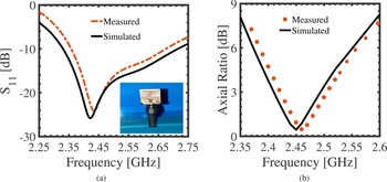
The Computer Simulation Technology (CST) Microwave Studio was used to perform full-wave simulation of the proposed antenna [19], and after optimization, the prototype of the proposed antenna was fabricated on FR-04 lossy substrate. The vector network analyzer was used to measure the various antenna radiation performance at Antenna Fabrication and Measurement Laboratory, G. B. Pant Institute of Engineering & Technology, Pauri. Figure 9(a) displays the measured and simulated S 11 versus the frequency, where a disparity between them is primarily due to the fabrication tolerance. According to measured S 11, a measured impedance bandwidth for the designed antenna is determined to be 2.330–2.716 GHz (15.8%).
Simulated and measured (a) S 11 and (b) AR frequency response of the designed antenna.

The simulated and measured axial ratio plots in the boresight direction are depicted in Fig. 9(b), which shows that the minimum axial ratio value achieved at 2.45 GHz bands. The 3 dB axial ratio bandwidth is 84 MHz (3.43%) in RFID 2.45 GHz band. It covers the RFID 2.45 GHz band sufficiently.
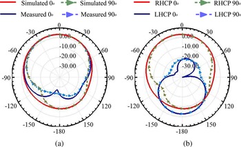
In an anechoic chamber, a linearly polarized (LP) horn antenna is used to measure the radiation patterns in x–z (horizontal) and y–z (vertical) plane directions. The simulated and measured radiation pattern at 2.45 in Fig. 10(a) exhibits symmetry in both principal planes with a small disparity between them, whereas symmetry is an essential requirement for circular polarization radiation. The simulated radiation patterns in horizontal and vertical planes for 2.45 GHz are illustrated in Fig. 10(b). The pattern is symmetry in both planes, and RHCP is superior by 30 dB than left-handed circularly polarization. Outstanding cross-polarization level (30 dB) is achieved in the broad-sight direction (θ = 0°).
Radiation patterns at x–z (ϕ = 0°) and y–z (ϕ = 90°) plane at 2.45 GHz: (a) simulated and measured results and (b) simulated results.

Figure 11(a) depicts the coordinate plots for the 3 dB AR at the center frequency of 2.45 GHz. It can be detected that the minimum AR in broad-sight (θ = 0°) is 0.43 dB. Also, the proposed design displays a wide half-power beamwidth of nearly 117° in the boresight direction. This performance has fulfilled the basic requirement of a wide coverage angle for RFID receiver systems. Figure 11(b) reveals the radiation efficiency, which persists over 85% throughout the RFID receiver band.
(a) Simulated and measured AR as a function of θ. (b) Simulated radiation efficiency as a function of frequency.

Simulated electric field intensity for several distances in the z-direction was presented to study the near field, as shown in Fig. 12. For this study, a perpendicular line at the center of the radiator was shown. Figure 12 shows the noticeable electric field below 25 mm in the z-axis at RFID 2.45 GHz band for the designed antenna.
Simulated near-field (electric field intensity) against distance.

Conclusion
A new design of a broadband circular polarized compact planar antenna for RFID receivers has been successfully implemented. The proposed structure used the concept of slots loaded parasitic element printed underneath a CPW-fed radiator to achieve the CP radiation and size reduction. The parasitic element loaded with F-slot and L-slot and a window-type slotted ground plane was used to achieve resonance at 2.45 GHz with RHCP radiation for RFID handheld reader application. With the wide 10 dB impedance bandwidth of 386 MHz (2.330–2.716 GHz), wide 3 dB beamwidth ($117^\circ$ ), wide 3 dB axial ratio bandwidth of 84 MHz (2.410–2.494 GHz), high gain (3.3 dBic) and outstanding cross polarization (>30 dB) and compact size, the antenna makes it appropriate for the RFID applications.
Acknowledgement
We highly acknowledge the Department of Electronics and Communication Engineering, Noida Institute of Engineering and Technology, India for providing the support regarding this work.
Financial support
This research received no specific grant from any funding agency, commercial, or not-for-profit sectors.
Conflict of interest
The authors declare that they have no known competing financial interests or personal relationships that could have appeared to influence the work reported in this paper.
 Niraj Agrawal received his Ph.D. degree in electronics and communication engineering from GBU in 2021. Presently, he is working as an assistant professor at NIET, Greater Noida (India). He has more than 7 years of teaching and research experience. His research interests include organic semiconductor materials, antenna, and microwave engineering. He has published more than 11 papers in refereed international journals. He has attended various training programs in the area of electronics and communication engineering.
 Anil Kumar Gautam received his B.E. degree in electronics and communication engineering from the Kumaon Engineering College, Almora, India, in 1999, and his Ph.D. degree in electronic engineering from the Indian Institute of Technology (BHU), Varanasi, India, in 2007. In 2000, he joined the Department of Electronics and Communication Engineering, Govind Ballabh Pant Institute of Engineering and Technology, Pauri Garhwal, India, as an assistant professor and promoted as associate professor in 2009. He has also worked as professor and dean at the School of Information and Communication Technology, Gautam Buddha University, Greater Noida, India from 2016 to 2018. He is currently working as professor at the Department of Electronics and Communication Engineering, Govind Ballabh Pant Institute of Engineering and Technology, Pauri Garhwal, India. He has supervised 30 M.Tech. and five Ph.D. theses and currently supervising three Ph.D. theses in microstrip antenna. He has authored or coauthored over 95 research papers published in the refereed international journals and conferences, such as the IEEE Transactions on Antenna and Propagation, IEEE Antenna and Wave Propagation Letters, Microwave and Optical Technology Letters, and so on. He has authored 13 books in electronics engineering with a focus on digital electronics, antenna, and microwave engineering. His current research interests include design and modeling of active microstrip antennas, microstrip antennas with defected ground structure, ultrawide bandwidth antennas, and reconfigurable antennas, reconfiguration antenna arrays, and circular polarized antennas.
 Karumudi Rambabu received his Ph.D. degree in electrical and computer engineering from the University of Victoria, Victoria, BC, Canada, in 2005. He was a research member with the Institute for Infocomm Research, Singapore, from 2005 to 2007. Since 2007, he has been an assistant professor with the Department of Electrical and Computer Engineering, University of Alberta, Edmonton, AB, Canada, where he is currently an associate professor. He is currently involved in oil well monitoring, pipeline inspection, through wall imaging, vital sign monitoring, and biopsy needle guiding using ultra-wideband (UWB) radar systems. His current research interests include design and development of UWB technology, and components and systems for various applications. Dr. Rambabu was the recipient of the Andy Farquharson Award for excellence in graduate student teaching from the University of Victoria in 2003 and the Governor Generals Gold Medal for the Ph.D. research in 2005. He served as an associate editor for the International Journal of Electronics and Communications.