Introduction
In recent years, microstrip antennas are present in many communication systems such as mobile telephony, wireless multimedia systems, or again spatial communications due to their practical advantages such as low profile, light weight, planar configuration, relatively cheap, and ease in fabrication and integration with solid-state devices. [Reference Ansari, Singh and Yadav1–Reference Guney and Kurt3]. However, these antennas suffer from some weak points such as low impedance bandwidth and gain level, which lead to their poor performance in some specific applications [Reference Razi, Rezaei and Valizade4]. To overcome this problem, extensive research has been conducted so far and many techniques have been suggested to improve the antenna bandwidth such as increasing patch height, reducing substrate permittivity, using multiple resonators, etc. [Reference Ansari, Singh and Yadav1, Reference Biswas and Mandal5–Reference Bedra and Fortaki7]. The addition of a superstrate layer over microstrip patch antenna has been reported to allow for the enhancement of the antenna gain and radiation efficiency, effectiveness and polarization of the antenna [Reference Zebiri, Lashab and Benabdelaziz8]. Superstrate or dielectric cover protects the patch from environmental hazards. The patch antennas designed without consideration of this superstrate effect will not perform as expected once installed in a portable unit, aircraft radome, and sensor design [Reference Biswas and Mandal5, Reference Bedra and Fortaki7]. Apart from covered microstrip patches, high-temperature superconducting thin films (denotes as ‘HTS’ in the following sections) offer unique properties which can be utilized for a variety of high-frequency device applications in many areas related to the strongly progressing market of information technology [Reference Klein9].
An HTS antenna was one of the first microwave components to be demonstrated as an application of HTS material [Reference Benmeddour, Dumond, Benabdelaziz and Bouttout10]. There are some distinct advantages of having HTS antennas. Primarily, present lower surface resistance in high T c superconducting thin films compared with normal conductors, corresponding to a higher quality factor [Reference Bouraiou, Benkouda and Fortaki11] and improved performance in passive microwave devices. Also, because of lower losses in superconductors, the reduction in size is another advantage using high T c superconducting thin films. The second significant achievement advantage is the frequency independent penetration depth, unlike the regular conductor. This means that dispersion introduced in superconducting devices will be negligible up to frequencies as high as hundreds of gigahertz. The third advantage is that liquid nitrogen cheaper than liquid helium, as a refrigerant, can be used for cooling the superconducting devices because high T c superconductors have T c above the boiling point of liquid nitrogen, 77 K [Reference Bedra and Fortaki12].
Besides giving some characteristics of microstrip antennas and an introduction into the microwave properties of HTS films, this paper provides an overview of the effects of both thin superstrate and anisotropy in the substrate on the resonant frequency, half-power bandwidth and quality factor of a high T c superconducting circular microstrip antenna for different structural parameter cases. In this paper, we extend the study carried out in [Reference Bedra and Fortaki7] by applying Galerkin's method in the Hankel transform domain (HTD) in conjunction with the complex resistive boundary condition to the analysis of the resonant characteristics of superconducting circular microstrip patch antenna with superstrate layer. In section ‘General formulation and structure of the problem’ of this paper, the authors briefly describe details of the application of the Galerkin's method in the HTD to the analysis of the superconducting circular microstrip resonators with superstrates layers. The validity of this method is proven in section ‘Numerical results and discussion’ by comparing our numerical results obtained for the resonant frequencies, half-power bandwidths and quality factors of microstrip patches covered by superstrates with theoretical and experimental data available in the literature. Also, in section ‘Numerical results and discussion’ original numerical results are presented for the effect of the superstrate layer on the resonant frequencies, quality factors and bandwidths of HTS circular antennas treated in the present paper. Finally, concluding remarks are summarized in section ‘Conclusion’.
General formulation and structure of the problem
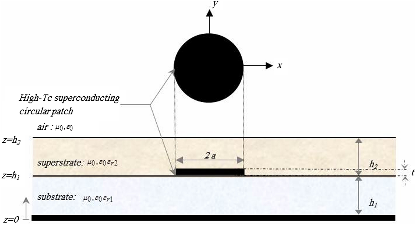
The high T c superconducting microstrip patch antenna considered in this work is shown in Fig. 1. The superconducting circular disc of radius a and thickness t sandwiched between a substrate of thickness h 1 with permeability μ 0 and permittivity  $\varepsilon _0\,\varepsilon _{r\,1}^{} $ and a superstrate layer of thickness h 2 with permeability μ 0 and permittivity
 $\varepsilon _0\,\varepsilon _{r\,2}^{} $. All fields and currents are time harmonic with the e jωt time dependence suppressed.
Geometry of the superconducting circular microstrip patch antenna with a radome.

The transverse fields inside the jth layer (j = 1;2) can be obtained via the inverse vector Hankel transforms (VHTs) as [Reference Bedra and Fortaki7]
 $$\eqalign{& {\bf E}(\rho, \phi, z) = \left[ {\matrix{ {E_\rho (\rho, \phi, z)} \cr {E_\phi (\rho, \phi, z)} \cr}} \right]\,\, = \cr & \quad \sum\limits_{n = - \infty} ^{n = + \infty} {e^{in\phi}} \int_0^\infty {dk_\rho k_\rho {\bar {\bf H}}_n} (\rho k_\rho ) \cdot {\bf e}_n(k_\rho, \,z),} $$
 $$\eqalign{& {\bf H}(\rho, \phi, z) = \left[ {\matrix{ {H_\phi (\rho, \phi, z)} \cr { - H_\rho (\rho, \phi, z)} \cr}} \right] = \cr & \quad \sum\limits_{n = - \infty} ^{n = + \infty} {e^{in\phi}} \int_0^\infty {dk_\rho k_\rho {\bar {\bf H}}_n} (\rho k_\rho ) \cdot {\bf h}_n(k_\rho, \,z).} $$
The kernel of the VHT is given by [Reference Fortaki, Khedrouche, Bouttout and Benghalia13]
 $${\bar {\bf H}}_n(\rho k_\rho ) = \left[ {\matrix{ {{{J}^{\prime}}_n(k_\rho \rho )} & { - \displaystyle{{in} \over {k_\rho \rho}} J_n(k_\rho \rho )} \cr {\displaystyle{{in} \over {k_\rho \rho}} J_n(k_\rho \rho )} & {{{J}^{\prime}}_n(k_\rho \rho )} \cr}} \right].$$
In equation (3), J n(·) is the Bessel function of the first kind of order n, and the prime denotes differentiation concerning the argument. In the VHT domain, the relation which relates the current kn(k ρ) on the conducting patch to the electric field in the corresponding interface is given by
 $${\bf e}_n(k_\rho, h_1) = {\bar {\bf G}}(k_\rho ) \cdot {\bf k}_n(k_\rho ).$$
In equation (4),  ${\bar {\bf G}}(k_\rho )$ is the dyadic Green's function of the considered structure in the vector HTD [Reference Bedra and Fortaki7]. Note that in the vector HTD, the dyadic Green's function is diagonal, and it is independent of the geometry of the radiating patch. It is given by
 $$\eqalign{& {\bar {\bf G}}(k_\rho ) = \left[ {\matrix{ {G^e} & 0 \cr 0 & {G^h} \cr}} \right] = \cr & \quad \displaystyle{1 \over {i\omega \varepsilon _0}}\left[ {\matrix{ {k_{z1}\displaystyle{{D^e} \over {T^e}}} & 0 \cr 0 & {k_0^2 \displaystyle{{D^h} \over {T^h}}} \cr}} \right]\,\sin \,(k_{z1}h_1)\,,} $$
in which
 $$D^e = k_{z0}\cos (k_{z2}h_2) + i\displaystyle{{k_{z2}} \over {\varepsilon _{r2}}}\sin \,(k_{z2}h_2),$$
 $$\eqalign{T^e = & \cos \,(k_{z2}h_2)\,\left[ {\varepsilon _{r1}k_{z0}\cos \,(k_{z1}h_1) + ik_{z1}\sin \,(k_{z1}h_1)} \right] \cr & + i\sin \,(k_{z2}h_2)\left[ \matrix{\displaystyle{{\varepsilon _{r1}} \over {\varepsilon _{r2}}}k_{z2}\cos \,(k_{z1}h_1) \hfill \cr \quad + i\varepsilon _{r2}k_{z0}\displaystyle{{k_{z1}} \over {k_{z2}}}\sin \,(k_{z1}h_1) \hfill} \right],} $$
 $$D^h = \cos \,(k_{z2}h_2) + i\displaystyle{{k_{z0}} \over {k_{z2}}}\sin \,(k_{z2}h_2),$$
 $$\eqalign{T^h = & \cos (k_{z2}h_2)\,\left[ {k_{z1}\cos (k_{z1}h_1) + ik_{z0}\sin (k_{z1}h_1)} \right] \cr & + i\sin (k_{z2}h_2)\left[ {k_{z0}\displaystyle{{k_{z1}} \over {k_{z2}}}\cos (k_{z1}h_1) + ik_{z2}\sin (k_{z1}h_1)} \right].} $$
In equations (5a)–(5d), k z1 and k z2 are, respectively, propagation constants in the first and second layers, and k z0 is the propagation constant in the free-space.
The transverse electric (TE) fields at the plane of the superconducting circular disc can be written as a superposition of an electric field in the circular disc and another out of the disc, this yields
 $${\bf e}_n(k_\rho, \,h_1) = {\bf e}_n^i (k_\rho, h_1) + {\bf e}_n^o (k_\rho, \,h_1).$$
The electric field in the superconducting patch is given by
 $${\bf e}_n^i (k_\rho, h_1) = {\bar {\bf Z}}_s \cdot {\bf k}_n(k_\rho ),$$
where 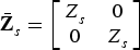 ${\bar {\bf Z}}_s^{} = \left[ {\matrix{ {Z_s^{}} & 0 \cr 0 & {Z_s^{}} \cr}} \right]$, and Z s is the surface impedance of the superconducting patch. It is described by the equation [Reference Bouraiou, Benkouda and Fortaki11]:
 $$Z_s = \left\{ {\matrix{ {\sqrt {{{\omega \cdot \mu _0} / {(2 \cdot \sigma )}}} } & {\,t \ge 3 \cdot \lambda _0} \hfill \cr \hskip -28pt{1/t \cdot \sigma } & {t \le 3 \cdot \lambda _0} \cr } } \right.$$
where σ is the complex conductivity of the superconducting film. It is determined by using London's equation and the Gorter–Casimir two-fluid model as [Reference Bedra and Fortaki12]
 $$\sigma = \sigma _1 - i\,\sigma _2.$$
The resistive part of the complex conductivity (σ 1) may arise from ordinary electron conduction within non-superconducting grains and scattering from grain boundaries, flux vibration at pinning centers, and normal electron conduction due to thermal agitation in the superconducting state. The temperature dependence of σ 1 is as follows [Reference Bedra and Fortaki12]
 $$\sigma _1 = \sigma _n\,\left( {\displaystyle{T \over {T_c}}} \right)^4,$$
where T is the temperature, T c is the transition temperature, and σ n is the normal state conductivity at T = T c. The reactive part of the conductivity (− iσ 2) arises from the lossless motion of the superconducting carriers which may be derived directly from the Lorentz-force equation as [Reference Bedra and Fortaki12]
 $$\sigma _2 = \displaystyle{1 \over {\omega \,\mu _0\,{[\lambda (T)]}^2}},$$
 $$\lambda (T) = \lambda _0 \cdot \left( {1 - {\left( {\displaystyle{T \over {T_c}}} \right)}^4} \right)^{1/2}.$$
In equation (10), ω is the angular frequency and λ(T) is the London penetration depth at temperature T. Substituting equation (6) into (4) yields
 $${\bf e}_n^o (k_\rho, \,h_1) = {\bar {\bf G}}(k_\rho ) \cdot {\bf k}_n(k_\rho ) - {\bf e}_n^i (k_\rho, \,h_1).$$
When equation (6) is substituted into (13), the following result is obtained:
 $${\bf e}_n^o (k_\rho, \,h_1) = \left( {{\bar {\bf G}}(k_\rho ) - {\bar {\bf Z}}_s^{}} \right) \cdot {\bf k}_n(k_\rho ).$$
The TE field out of the superconducting disc can be expressed via the inverse VHT as follows:
 $$\eqalign{& {\bf E}_n^o (\rho, \,h_1) = \quad \int_0^{ + \,\,\infty} {dk_\rho k_\rho {{\bar {\bf H}}}_n(k_\rho \rho ) \cdot} {\rm} \left( {{\bar {\bf G}}(k_\rho ){\rm} - {\bar {\bf Z}}_s^{}} \right) \cdot {\bf k}_n(k_\rho )} $$
where  ${\bar {\bf H}}_n(k_\rho \rho )$ is the kernel of the VHT.
Now that we have the necessary Green's function, it is relatively straightforward to formulate the moment method solution for the antenna characteristics. To solve the integral equation, we apply the procedure of Galerkin which consists of developing the unknown distribution of the current on the circular patch is expanded into a series of basis functions [Reference Fortaki, Khedrouche, Bouttout and Benghalia13]. Boundary conditions require that the transverse components of the electric field vanish on the perfectly conducting disk and the current vanishes off the superconducting disk, to give the following set of vector dual integral equations:
 $$\eqalign{& {\bf E}_n^o (\rho, \,h_1) = \int_0^{ + \,\infty} {dk_\rho k_\rho {{\bar {\bf H}}}_n(k_\rho \rho ) \cdot} \cr & \quad {\rm} \left( {{\bar {\bf G}}(k_\rho ){\rm} - {\bar {\bf Z}}_s^{}} \right) \cdot {\bf k}_n(k_\rho ) = {\bf 0}, \quad \rho \lt a,} $$
 $${\bf K}_n^{} (\rho ) = \int_0^{ + \,\infty} {dk_\rho k_\rho {{\bar {\bf H}}}_n(k_\rho \rho ) \cdot} \,{\bf k}_n(k_\rho ) = {\bf 0}, \quad \rho \gt a.$$
Galerkin's method is employed to solve the coupled vector integral equations (16) and (17). The current on the disk is expressed in the form of a series of basis functions as follows:
 $${\bf K}_n(\rho ) = \sum\limits_{\,p = 1}^P {a_{np}{\bf \psi} _{np}} (\rho ) + \sum\limits_{q = 1}^Q {b_{nq}{\bf \Phi} _{nq}} (\rho ).$$
P and Q correspond to the number of basis functions of ψnp(ρ) and Φnq(ρ), respectively, a np and b nq are the mode expansion coefficients to be sought. The corresponding VHT of the current is given by
 $${\bf k}_n(k_\rho ) = \sum\limits_{\,p = 1}^P {a_{np}\psi _{np}} (k_\rho ) + \sum\limits_{q = 1}^Q {b_{nq}\phi _{nq}} (k_\rho ).$$
Substituting the current development (18) into (17), then multiplying the resulting equation by  $\rho \,{\bf \psi} ^ + _{nk} (\rho )$ (k = 1, 2…, P) and by
 $\rho \,{\bf \Phi} ^ + _{nl} (\rho )$ (l = 1, 2…,Q), and integrating from 0 to a, and using the Parseval's theorem for VHT [Reference Fortaki, Khedrouche, Bouttout and Benghalia13], we obtain a system of linear P + Q algebraic equations for each mode n which can be written in the matrix form:
 $${\bar {\bf Z}}_n \cdot {\bf C}_n = {\bf 0}{\rm,} $$
where
 $$\eqalign{{\bar Z}_n &= \left[ {\matrix{ {{({\bar Z}{_n^{}} ^{{\bf \psi \psi}} n)}_{P \times P}} & {{({\bar Z}{_n^{}} ^{{\bf \psi \Phi}} )}_{P \times Q}} \cr {{({\bar Z}{_n^{}} ^{{\bf \Phi \psi}} n)}_{Q \times P}} & {{({\bar Z}{_n^{}} ^{{\bf \Phi \Phi}} n)}_{Q \times Q}} \cr}} \right], \cr C_n &= \left[ {\matrix{ {{(a_n)}_{\,p \times 1}} \cr {{(b_n)}_{q \times 1}} \cr}} \right].}$$
Each element of the submatrices is given by
 $$\bar {\bf Z}_n^{{\bf VW}} {\rm (}i,\,j{\rm )} = \int_0^{ + \infty} {dk\rho {\bf V}_{ni}^ +} {\rm (}k_\rho {\rm )} \cdot \left( {{\bar {\bf G}}{\rm (}k_\rho {\rm )} - \bar {\bf Z}_s^{}} \right) \cdot {\bf W}_{nj}{\rm (}k_\rho {\rm ),}$$
where V and W represent either εψε or εΦε, for every value of the integer n. The non-trivial solutions can exist, if the determinant of Equation (19) vanishes, that is:
 $$\det \,\left[ {{\bar {\bf Z}}_n(\omega )} \right]^{} = 0$$
Equation (23) is an eigenequation for ω, from which the characteristics of the structure of Fig. 1 can be obtained. In fact, let  $\omega ^{n m} = 2\pi (f_r^{n m} + if_i^{n m} ) (n = 0,1,2, \ldots ; \,m = 1,2, 3, \ldots )$ be the set of complex roots of equation (23). In that case, the quantities
 $f_r^{n m} $ stand for the resonant frequencies of the resonant modesεTMn mε, the quantities
 $BW^{n m} = 2f_i^{n m} /f_r^{n m} $ stand for the bandwidths, and the quantities
 $Q^{n m} = f_r^{n m} /(2f_i^{n m} )$ stand for the quality factors [Reference Bedra and Fortaki7].
One set of basis functions taken are those currents associated with the complete orthogonal set of transverse magnetic (TM) and TE modes of a cylindrical cavity of the radius a with magnetic side walls and electric top and bottom walls. These current modes which are non-zero only on the patch are given by [Reference Fortaki, Khedrouche, Bouttout and Benghalia13]
 $$\eqalign{{\bf \psi} _{np}(\rho ) & = \left[ {\matrix{ {{{J}^{\prime}}_n({{\beta _{n p}\rho} / a})} \cr {\displaystyle{{i na} \over {\beta _{n p}\rho}} J_n({{\beta _{n p}\rho} / a})} \cr}} \right], \cr {\bf \Phi} _{nq}(\rho )& = \left[ {\matrix{ {\displaystyle{{ - i na} \over {\alpha _{n q}\rho}} J_n({{\alpha _{n q}\rho} / a})} \cr {{{J}^{\prime}}_n({{\alpha _{n q}\rho} / a})} \cr}} \right],} $$
for εn = 0, + 1, + 2, …ε. εψnp(ρ) (p = 1, 2, …, P)ε correspond to the TM cavity modes and εΦnq(ρ)ε (q = 1, 2, …, Q) correspond to the TE cavity modes. The constants εβ n pε and εα n qε correspond to the pth and qth zeros of  ${J}^{\prime}_n(\beta _{n p}) = 0$ and εJ n(α n q) = 0ε, respectively.
The second set of basis functions taken have different expressions for axial-symmetric resonant modes (n = 0) and for non-axial symmetric resonant modes (n ≠ 0). In the case of axial-symmetric modes, the basis functions which are non-zero only on the patch are given by [Reference Fortaki, Khedrouche, Bouttout and Benghalia13]
 $${\bf \psi} _{0p}{\rm (}\rho {\rm )} = \left[ {\matrix{ {U_{{\rm 2}p - 1}{\rm (}{\rho / a}{\rm )}\sqrt {1 - {{\rm (}{\rho / a}{\rm )}}^{\rm 2}}} \cr 0 \cr}} \right],$$
where U 2p -1(·)(p = 1, 2, …, P) stand for Chebyshev polynomials of the second kind [Reference Fortaki, Khedrouche, Bouttout and Benghalia13]. For non-axial symmetric modes, the basis functions which are non-zero only on the patch are given by
 $$\eqalign{ {\bf \psi} _{np}{\rm (}\rho {\rm )} & = \left[ {\matrix{ {{{\rm (}{\rho / a}{\rm )}}^{n - {\rm 2}}{\rm} U_{{\rm 2}p - 1}{\rm (}{\rho / a}{\rm )}\sqrt {1 - {{\rm (}{\rho / a}{\rm )}}^{\rm 2}}} \cr 0 \cr}} \right], \cr {\bf \Phi} _{nq}{\rm (}\rho {\rm )} & = \left[ {\matrix{ 0 \cr {i\,{{\rm (}{\rho / a}{\rm )}}^{n - {\rm 1}}{\rm} \displaystyle{{T_{{\rm 2}q - 2}{\rm (}{\rho / a}{\rm )}} \over {\sqrt {1 - {{\rm (}{\rho / a}{\rm )}}^{\rm 2}}}}} \cr}} \right],} $$
where T 2q -2(·) (q = 1, 2, …, Q) stand for Chebyshev polynomials of the first kind. The term $\sqrt {1 - {{\rm (}{\rho / a}{\rm )}}^{\rm 2}} $ provides for the proper singular edge behavior for the azimuthal current K ϕ and the zero edge condition for the radial current K ρ[Reference Fortaki, Khedrouche, Bouttout and Benghalia13].
The integrands for the integrals for the matrix elements of (5a)–(5d) are singular when D e or D h is zero. The integrals are evaluated numerically, using a composite 8 points Gauss-Legendre rule, along with an integration path deformed above the real axis to avoid the singularities. Also, Muller's method which involves three initial guesses is used for root-seeking of (23).
Numerical results and discussion
In the previous section, Galerkin's method in the vector HTD has been used for the numerical calculation of the resonant frequencies, bandwidths and quality factors of the resonant modes εTMn mε of HTS circular microstrip patch with superstrate layer. Knowing the parameters of the antenna: thicknesses and relative permittivities of the first and second layers (h 1, εr1, h 2, εr2) as well as the radius of the circular patch (a), while the superconducting parameters are included in the surface complex impedance formula, one can easily calculate the complex roots of the characteristic equation ( $\det \left[ {{\bar {\bf Z}}_n(\omega )} \right] = 0$). The complex roots of the characteristic equation are the complex resonant frequencies of the resonant modesεTMn mε. As shown in equation (23), the elements of the matrix
 ${\bar Z}_n{\rm (}\omega {\rm )}$ depend on the dyadic Green's function
 ${\bar {\bf G}}(k_\rho )$ as well as the basis functions Ψ or Φ. The parameters h 1, εr1, h 2, εr2 are included in the expression of
 ${\bar {\bf G}}(k_\rho )$ (see equations (5) and (5a)–(5d)). However, the radius of the patch a is included in the expression of the basis functions Ψ or Φ.
As in the case of perfectly conducting circular discs, we have found that these basis functions are very appropriate to the vector HTD analysis of superconducting circular discs. Since the mode n = 1 (TM11) of the circular disc is highly used in the applications of microstrip antennas, in what follows only numerical results for this fundamental mode are given.
Convergent results for the resonant frequency and bandwidth using cavity modes basis functions are obtained with (P = 4, Q = 5), while those using Chebyshev polynomials basis functions with the edge singularity required only (P = 4, Q = 4). Note that the CPU time required to compute the integral depends on the number of basis functions, as well as on the length of the integration shown in equation (22). We have found that the length of the integration required to reach numerical convergence when Chebyshev polynomials basis functions are used is about twice of that required when cavity modes basis functions are used. This is attributed to the fact that when using Chebyshev polynomials basis functions, the integrands vary asymptotically as  $1/k_\rho ^2 $, while those using cavity modes basis functions vary asymptotically as
 $1/k_\rho ^3 $.
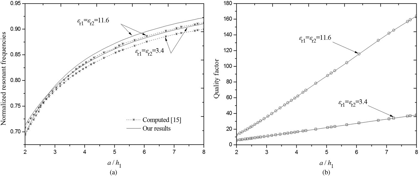
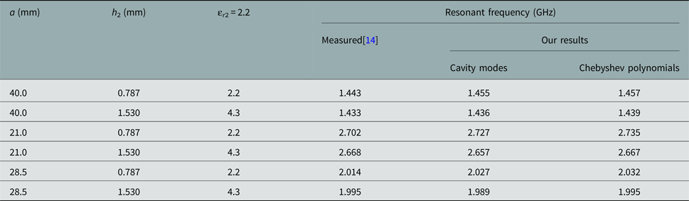
In order to check the validity of the method described in section ‘General formulation and structure of the problem’, our results for the resonant frequencies, bandwidths and quality factors of circular microstrip patches with radomes have been compared with previously published results [Reference Kumar and Malathi14, Reference Losada, Boix and Horno15]. Good agreement has been found in all cases (see Table 1 and Fig. 2). In Table 1, the computed values of the resonant frequencies of superstrate loaded conducting circular patches using both cavity modes, and Chebyshev polynomials basis functions are compared with recently experimental values available in the open literature [Reference Kumar and Malathi14]. It is clear that the results of the present analysis are close to the experiment. Note that our calculated resonant frequencies using cavity modes basis functions differ from those using Chebyshev polynomials basis functions by at most 0.57%.
Normalized resonant frequency (a) and quality factor (b) of conducting circular microstrip with a dielectric superstrate of the same type, εh 1 = h 2 = 0.635mmε.

Comparison of calculated and experimental resonant frequency for a superstrate-loaded circular patch antenna; εh 1 = 0.787mmε, εr1 = 2.2.

The variation of fundamental mode resonant frequency with a radius of the patch using cavity modes basis functions is visualized in Fig. 2(a). It is evident to observe from this figure that the approach reported elsewhere yield comparable results. The very good agreement of our computed values with the experimental measurements [Reference Losada, Boix and Horno15] is a clear indication of the validity of the method proposed in this work. Also, numerical results for the half-power bandwidth as a function of the radius of circular patches using two different permittivity superstrate, and shown in Fig. 2(b).
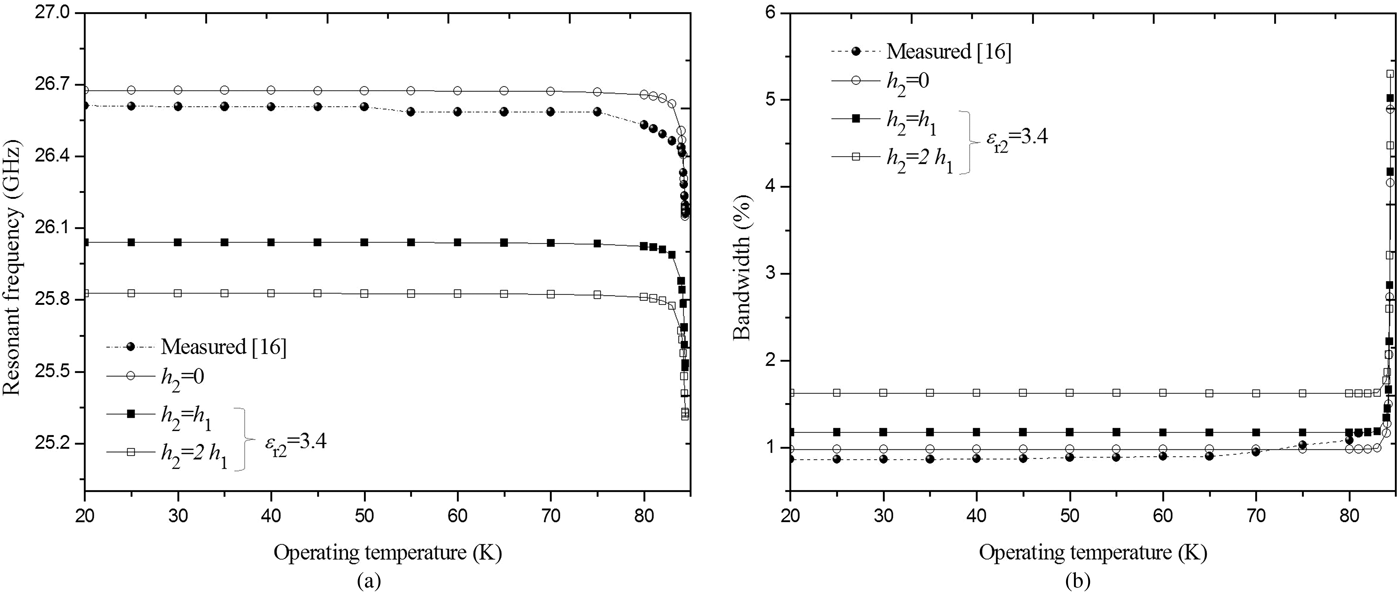
To check the present theory for a superconducting circular microstrip patch with and without superstrate, shown in Fig. 1, we compared our results with the experimental results of Richard et al. [Reference Richard, Bhasin and Claspy16]. The circular patch has a radius of εa = 610μmε, fabricated using a YBCO (YBa2Cu3O7) superconducting thin film of thickness εt = 330nmε with a normal state conductivity at the transition σ n = 106 S/m, a zero-temperature penetration depth ελ 0 = 140nmε and with a critical temperature εT c = 84.5Kε.The superconducting patch printed on a lanthanum aluminate substrate (LaAlO3) of thickness εh 1 = 254μmε, with permittivity εr1 = 23.81.
An excellent agreement with the experiment by [Reference Richard, Bhasin and Claspy16] is evident in Figs 3(a) and 3(b). It is noticed that the resonant frequencies of the superconducting patches without superstrate are larger than those obtained with superstrate. This result agrees with that discovered theoretically for perfectly conducting patches [Reference Bedra and Fortaki7]. The effects of operating temperature of the superconducting film on the bandwidth of high T c superconducting circular patch are also investigated in Fig. 3(b). It is seen that when the superstrate thickness increases, the bandwidth increases because dielectric cover causes the change in the fringing fields between the antenna and the ground plane thus affecting the substrate's equivalent permittivity.
Resonant frequency (a) and bandwidth (b) of superconducting circular microstrip for various thickness of superstrate as a function of operating temperature;εr1 = 23.81, εh 1 = 254μmε, εa = 610μmε, εt = 330nmε, ελ 0 = 140nmε, εT c = 84.5Kε, εσ n = 106S/mε.

From the results of Figs 3(a) and 3(b), it is observed that the effect of varying the temperature on the resonant frequency and bandwidth is significant only for temperatures near the transition temperature. This behavior agrees with that discovered experimentally by Richard et al. [Reference Richard, Bhasin and Claspy16] for single-layer superconducting microstrip antennas.
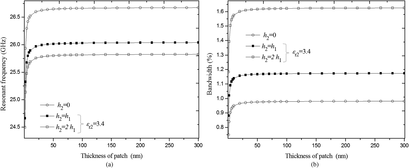
In Figs 4(a) and 4(b), we investigate the influence of the thickness of patch on the resonant frequency and bandwidth of the high T c superconducting antenna with and without superstrate layer. The parameters of the antenna are identical to those used in Fig. 3 (εT = 50Kε). The resonant frequency of the superconducting antenna against the thickness of superconducting patch for different superstrate thickness is shown in Fig. 4(a), the presence of a dielectric cover shifts the resonance to the lower frequency. Figure 4(b) presents the variation of the bandwidth of the antenna as a function of the thickness of superconducting patch for different superstrate thickness. As Observed, a considerable improvement of the superconducting antenna bandwidth is obtained by increasing the thickness of the superstrate layers. Concerning the effect of the thickness of the superconducting film, it is also observed that as the thickness of patch grows, the resonant frequency and bandwidth increases quickly until the thickness t reaches λ 0/3. When t exceeds this value, increasing the superconducting thickness will increase slowly the resonance frequency as well as the bandwidth.
Resonant frequency (a) and bandwidth (b) of superconducting circular microstrip for various thickness of superstrate as a function of the thickness of superconducting patch; εr1 = 23.81, εh 1 = 254μmε, εa = 610μmε, εT = 50Kε, ελ 0 = 140nmε, εT c = 84.5Kε, εσ n = 106S/mε.

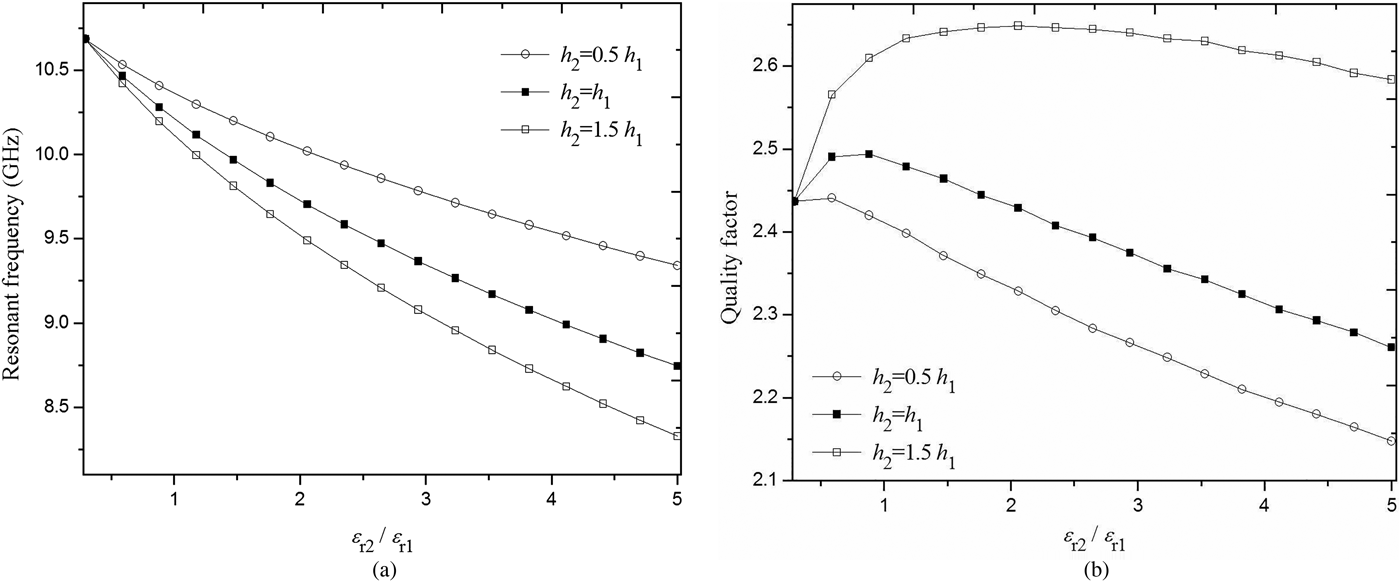
In Fig. 5, results are presented for the resonant frequencies and bandwidths of the fundamental resonant mode of a superconducting circular microstrip patch with different values of superstrate parameters.
Resonant frequency (a) and bandwidth (b) as a function of normalized superstrate permittivity for different values of normalized superstrate thickness of superconducting circular patch; εr1 = 3.4, εh 1 = 508μmε, εa = 4.27mmε, εT = 50Kε, ελ 0 = 140nmε, εT c = 84.5Kε, εσ n = 106S/mε.

The circular patch is fabricated with a YBCO superconducting thin film with parameters εσ n = 106S/mε, ελ 0 = 140nmε, εT c = 84.5K,ε and εt = 350nmε. The patch radius is εa = 4.27mmε and the dielectric substrate with relative permittivity of εr1 = 3.4, and a thickness of εh 1 = 508μmε. The operating temperature is εT = 50Kε. The effect of superstrate on the resonant frequency is shown in Fig. 5(a). In this plot, we have studied the variation of the resonant frequency as a function for different values of superstrate thicknesses h 2. It is observed that the resonant frequency decreases with the increase of superstrate permittivity εr2, this change is pronounced for higher values of εr2. Finally, Fig. 5(b) shows that the effect of the superstrate on the quality factor of the superconducting circular patch analyzed is stronger as both the thickness and permittivity of the superstrate increase. Again from this figure, it is clear that the quality factor is more stringent in higher values of superstrate parameters. Hence, it is possible to tune the antenna by the application of the superstrate.
Conclusion
An efficient full-wave analysis based on Galerkin's method in the HTD in conjunction with the concept of the complex resistive boundary condition has been used for the numerical calculations of the resonant characteristics of HTS microstrip resonators with dielectric radomes. The numerical results obtained for the resonant frequencies, half-power bandwidths and quality factors of superconducting circular patches covered with dielectric radomes have been compared with measurements and with numerical results available in the open literature. Good agreement has been found in all cases. Original results have been presented for the resonant frequencies and bandwidths of patches fabricated using a YBCO and covered by a superstrate layer, which shows that the effects of both thickness and permittivity of superstrate are significant and cannot be neglected. Also, another interesting result was obtained, which is not discussed in the literature, the conjugate effect of the superstrate parameters on the resonant characteristics of the perfectly conducting patch as well as for the superconducting patch. It has been noticed that by increasing the permittivity, the superstrate thickness effect becomes high, especially for the bandwidth of the superconducting patches. The analytical formulation introduced here can be extended to the case HTS circular microstrip resonators in multilayered media containing uniaxial anisotropic dielectrics materials.
 Sami Bedra was born on August 03, 1984 in Khenchela, Algeria. He received the Master Science and Ph.D. degrees in Electronics Engineering from University of Batna, Algeria, in 2011 and 2015, respectively. Currently, he is an Associate Professor in the Department of Industrial Engineering at Khenchela University, Algeria. He has published 20 papers in refereed journals and more than 15 papers in conference proceedings. He serves as reviewer for several technical journals. His current research activities include neural network, optimization techniques, and their applications to conducting and superconducting microstrip patch antennas.
 Randa Bedra was born on September 09, 1989 in Batna, Algeria. She received the Master Science in Microwave and Telecommunications from University of Batna, Algeria, in 2013. She is currently with the Laboratory of Advanced Electronics at Electronics Department, University of Batna, Batna, Algeria. She is currently working towards a Ph.D. degree at the University of Batna 2. Her main research deals with numerical methods and microstrip antennas.
 Siham Benkouda was born on August 30, 1983 in Arris, Algeria. She received the Master Science and Ph.D. degrees in Electronics Engineering from University of Batna, Algeria, in 2008 and 2012, respectively. She is currently with the Laboratory of Ultrahigh Frequencies and Semiconductors at Electronics Department, University of Constantine 1, Constantine, Algeria. Her main research deals with numerical methods and microstrip antennas.
 Tarek Fortaki was born on March 31, 1972 in Constantine, Algeria. He received the Engineer of Communication degree in 1995, the Master Science degree in Microwaves in 1999, and the Doctorate degree in Microwaves in 2004, all from the Electronics Department, Faculty of Engineering Science, University of Constantine. Currently he is a Professor at the Electronics Department, Faculty of Engineering Science, University of Batna 2. He has published 40 papers in refereed journals and more than 40 papers in conference proceedings. He serves as reviewer for several technical journals. His main interests are electromagnetic theory, numerical methods and modeling of antennas and passive microwave circuits.