





1. Introduction
The search for non-equilibrium media with an inverse distribution of particles by energy states is crucial for the development of science and practice. Bekefi, Hirshfield & Brown (Reference Bekefi, Hirshfield and Brown1961) showed almost immediately after the creation of the first gas lasers that a medium with inverse free electron distribution function (EDF) in gases with a Ramsauer minimum of the elastic scattering cross-section has an absolute negative conductivity of the electron gas, and thus it will amplify electromagnetic waves in a wide frequency range.
It is shown in Bekefi et al. (Reference Bekefi, Hirshfield and Brown1961) that the absorption coefficient
 $\alpha _\omega$
of radiation with frequency
 $\omega$
by plasma is uniquely determined by the electronic conductivity
 $\sigma _r$
:
 \begin{align} \alpha _\omega = \sigma _r/{\varepsilon _0}c,\quad \sigma _r = - \int {\frac { 4\pi e N n }{3m\,\omega ^2} R(v)\frac {\partial f(v)}{\partial v} v^4 \,{\rm d}v}, \end{align}
where
 $f(v)$
is the electron velocity distribution function,
 $\varepsilon _0$
is the vacuum permittivity,
 $c$
is the light velocity,
 $m$
is the electron mass,
 $n$
is the electron density,
 $N$
is the gas density and
 $R(\omega )$
is the effective absorption coefficient, which is determined by the electron momentum transfer cross-section
 $Q_m(v)$
:
 \begin{align} R\left ( v \right ) = \frac {{{\omega ^2}{Q_m}\left ( v \right )}}{{{\omega ^2} + {{\left [ {N\,v\,{Q_m}\left ( v \right )} \right ]}^2}}}. \end{align}
A necessary condition for negative conductivity
 $\sigma _r \lt 0$
is the fulfilment of the inequality
 $\partial [ v^4 R( v ) ]/\partial v\, \lt \,0$
, which is possible with a sharp decrease in the cross-section
 $Q_m(v)$
in some range of velocities. This condition can be fulfilled, in particular, in inert gases with a Ramsauer minimum.
Another necessary condition for
 $\sigma _r \lt 0$
is the inversion of the EDF. By the inversion of the EDF is meant the situation when the EDF increases with increasing velocity (or kinetic energy) in some range of velocities:
 $\partial f(v)/\partial v\, \gt 0$
. Of particular interest is the inversion of the EDF in the region of low kinetic energies and, in particular, at zero kinetic energy,
 ${ {( {\partial {f_0}/\partial w})} |_{w = 0}} \gt 0$
, since this region determines the main integral characteristics of the electron gas (note that the transition from
 $v$
to
 $w$
is necessary in the case of
 $v=0$
due to the fact that
 $\partial /\partial v = m v \; \partial /\partial w$
and, hence,
 $\partial /\partial v = 0$
at
 $v=0$
).
Thus, the study of the conditions of the inversion of the EDF at zero kinetic energy is extremely important for solving the problem of amplification of electromagnetic waves by plasma.
However, in contrast to laser technology, based on the inversion of the bound electron states of atoms and molecules, this problem of creating an inverse EDF is not solved yet. Thus, a reasonable question arises: why did this situation arise? In our opinion, the main reason for this situation is the fact that the search of inverse EDF and absolute negative conductivity has typically been based on an oversimplified kinetic equation for electrons. The original space-dependent kinetic equation in these cases is reduced to a spatially homogeneous equation that depends on only one variable: the electron’s kinetic energy
 $w$
.
In our previous works (Yuan et al. Reference Yuan, Yao, Bogdanov, Kudryavtsev and Zhou2020; Chai et al. Reference Chai, Yao, Bogdanov, Kudryavtsev, Yuan and Zhou2021; Yuan et al. Reference Yuan, Chai, Bogdanov and Kudryavtsev2022) it was demonstrated that the main reason for the current situation is that the search for an inverse EDF in the literature has typically involved a significant simplification of the Boltzmann kinetic equation, assuming a spatially homogeneous medium where the equation depends only on a single variable (the electron velocity) (see Dyatko Reference Dyatko2007).
A real laboratory plasma is always bounded and the EDF depends on the spatial coordinates. To take this inevitable fact into account, this paper develops a novel approach for solving the problem of practical implementation of an inverse EDF.
In Yuan et al. (Reference Yuan, Yao, Bogdanov, Kudryavtsev and Zhou2020) and Chai et al. (Reference Chai, Yao, Bogdanov, Kudryavtsev, Yuan and Zhou2021), it was shown that for the formation of EDF inversion at
 $w=0$
, the inequality
 \begin{align} {\left . {\left ( {\boldsymbol{\nabla }\varphi \, \boldsymbol{\cdot }\,\boldsymbol{\nabla }{f_0}} \right )} \right |_{w = 0}} \lt 0 \end{align}
should be satisfied, where
 $\varphi$
is the electric potential. Condition (1.3) can be satisfied only in a non-uniform plasma. For example, when the electric field accelerates electrons towards the anode, but the EDF decreases in this direction. Also, it can be observed that (1.3) is inconsistent with the traditional Boltzmann distribution
 $n_e \sim \text{exp}(\varphi / T_e)$
(
 $n_e$
and
 $T_e$
are the electron density and electron temperature, respectively).
To use the kinetic criterion (1.3), extremely resource-intensive kinetic modelling for at least two-dimensional geometry is required. However, there is a simpler way to estimate the fulfilment of inequality (1.3). Since the EDF in the low-energy region makes the main contribution to the electron density, the profiles should be similar:
 $n_e( \boldsymbol{x} ) \sim {f_0} ( \boldsymbol{x}, w = 0 )$
. Then condition (1.3) yields a simpler heuristic fluid criterion, identifying the areas of the most probable implementation of the EDF inversion in various gas discharges:
 \begin{align} \boldsymbol{\nabla }\varphi \boldsymbol{\cdot }\boldsymbol{\nabla }{n_e} \lt 0. \end{align}
Criterion (1.4) depends on spatial distributions and the electron density (not on the EDF). Note that (1.4) is a strict criterion for the case where the EDF can be factorised as
 $f_0(\boldsymbol{x},w)=n_e(\boldsymbol{x})F(w)$
which corresponds to the local field approximation. However, in general, the EDF cannot be factorised, and conditions are possible when inequality (1.4) holds, but the EDF has no inversion. An example of such an EDF and a more detailed discussion of criterion (1.4) are given in Bogdanov, Kudryavtsev & Yuan (Reference Bogdanov, Kudryavtsev and Yuan2026). Thus, preliminary searches for media with inverse EDF can be conducted using some version of the fluid model. For these models, which do not require large computational resources, many commercial software environments are available (ESI 2014; COMSOL 2022).
Thus, when searching for the conditions of inverse EDF creation, the spatial non-uniformity of the plasma parameters of experimental devices should be taken into consideration (Yuan et al. Reference Yuan, Yao, Bogdanov, Kudryavtsev and Zhou2020; Chai et al. Reference Chai, Yao, Bogdanov, Kudryavtsev, Yuan and Zhou2021). Under such conditions, the EDF is non-local (Tsendin Reference Tsendin1995), because the unsimplified kinetic equation, which depends on both energy and spatial variables, should be solved to find it. The equation includes also the self-consistent electric (ambipolar) field.
On the one hand, this makes the procedure for solving the kinetic equation for electrons more complex. On the other hand, this increases the number of degrees of freedom of the system and results in new scenarios for EDF formation. In particular, in the Boltzmann equation, the divergence of the spatial flow is a source (or sink) capable of providing the EDF inversion.
Theoretical analysis and numerical modelling of the longitudinal structure of a classical direct-current glow discharge (CGD), which is the most thoroughly studied plasma object, were also conducted in Yuan et al. (Reference Yuan, Yao, Bogdanov, Kudryavtsev and Zhou2020) and Chai et al. (Reference Chai, Yao, Bogdanov, Kudryavtsev, Yuan and Zhou2021). The convenience and simplicity of its implementation and experimental study made the CGD a traditional object for testing new ideas and diagnostics in plasma physics.
Based on the results of analytical models (Kudryavtsev, Morin & Tsendin Reference Kudryavtsev, Morin and Tsendin2008; Yuan, Kudryavtsev & Demidov Reference Yuan, Kudryavtsev and Demidov2018) and numerical simulation (Yuan et al. Reference Yuan, Bogdanov, Eliseev and Kudryavtsev2017, Reference Yuan, Yao, Bogdanov, Kudryavtsev and Zhou2020; Chai et al. Reference Chai, Yao, Bogdanov, Kudryavtsev, Yuan and Zhou2021) of the longitudinal structure of the CGD with flat electrodes, the following conclusions can be made. In a one-dimensional short (without positive column (PC)) glow discharge, consisting only of a cathode layer and plasma of negative glow (NG), only one field-reversal point is observed at the maximum of the plasma density (Kudryavtsev et al. Reference Kudryavtsev, Morin and Tsendin2008; Yuan et al. Reference Yuan, Kudryavtsev and Demidov2018). Under these conditions, criterion (1.3) cannot be fulfilled. This is due to the fact that the electric field decelerates electrons towards the anode when the electron density decreases (and vice versa).
However, a longer CGD with the formation of a PC is already (2D), since the existence of a PC requires the presence of walls in the direction transverse to the current (Raizer Reference Raizer1991). Therefore, in the transition region from the Faraday dark space to the PC, a second field-reversal point is formed, behind which the field accelerates the electrons towards the anode (Kudryavtsev et al. Reference Kudryavtsev, Morin and Tsendin2008; Yuan et al. Reference Yuan, Kudryavtsev and Demidov2018). Therefore, criterion (1.3) is satisfied there and the EDF is inverse, as long as the electron density decreases from its maximum value in the NG (Yuan et al. Reference Yuan, Yao, Bogdanov, Kudryavtsev and Zhou2020; Chai et al. Reference Chai, Yao, Bogdanov, Kudryavtsev, Yuan and Zhou2021). The analysis shows that the size and position of this region depend on many factors. The latter include the ionisation characteristics and range of non-local fast electrons that have gained their energy in the strong field of the cathode layer, the ratio between the length
 $L$
and radius
 $R$
of the discharge tube and the spatial distributions of the self-consistent electric field, electron density and electron temperature. All these factors can reduce the region of EDF inversion and significantly complicate interpretation of the obtained data, since the final result is often sensitive even to minor parameter changes.
To minimise the aforementioned factors preventing creation of an inverse EDF, a two-dimensional modification of the CGD should be proposed, where these factors act more independent of each other. Thus, when using a hollow cathode (HC), the electrons emitted from its surface are accelerated mainly in the radial direction that is perpendicular to the direction of discharge current (Arslanbekov & Tobin Reference Arslanbekov, A. and Tobin1998). Therefore, almost all ionisation and the resulting NG plasma are concentrated inside the HC. In turn, if the length
 $L$
of the outer region between the HC and anode is insufficient for the formation of a PC (
 $L\lt \lambda _{\epsilon }$
, where
 $\lambda _\epsilon$
is the energy relaxation length (Tsendin Reference Tsendin1995)), then there is no ionisation in it (excluding a narrow region of anode layer adjacent to the anode itself). Then this transition region with a weak field is an analogue of the Faraday dark space of the CGD and serves only for transporting electrons formed inside the HC to the anode. Since, in the absence of ionisation, the plasma density decreases towards the anode, condition (1.3) will be fulfilled.
In this paper, we formulate and substantiate the new approach for obtaining the inverse EDF. It is shown by solving the non-local Boltzmann equation that in a HC discharge, the inverse EDF is realised in the gap between cathode and anode. Thus, the main results formulated earlier (Yuan et al. Reference Yuan, Yao, Bogdanov, Kudryavtsev and Zhou2020; Chai et al. Reference Chai, Yao, Bogdanov, Kudryavtsev, Yuan and Zhou2021) for one-dimensional kinetic models are extended to a more realistic two-dimensional case. Based on the results of the conducted numerical modelling and theoretical analysis, practical recommendations are developed and specific conditions are identified for the experimental detection of an inverse EDF in a HC glow discharge.
2. Results and discussion
For a detailed analysis, we will further consider the results of simulations with the solution of the non-local Boltzmann kinetic equation for the isotropic component
 $f_0$
(Yuan et al. Reference Yuan, Yao, Bogdanov, Kudryavtsev and Zhou2020; Chai et al. Reference Chai, Yao, Bogdanov, Kudryavtsev, Yuan and Zhou2021):
 \begin{align} \boldsymbol{\nabla }\boldsymbol{\cdot }{\boldsymbol{\varPhi }} +\frac {\partial \varGamma }{\partial w} = S^{*}\left ( f_0 \right ), \end{align}
 \begin{align} \boldsymbol{\varPhi } = \frac {\gamma }{3} \sqrt {w}\,\boldsymbol{f}_{\kern-2pt 1} ,\quad \varGamma = -\boldsymbol{E}\boldsymbol{\cdot }{\boldsymbol{\varPhi }} - w^{3/2} \kappa \nu _a \left (T\,\frac {\partial f_0}{\partial w} + f_0 \right ) , \end{align}
where
 $\boldsymbol{\varPhi }$
and
 $\varGamma$
are respectively
 $\unicode{x1D6F7}$
the spatial and energy phase fluxes,
 $\gamma = \sqrt {2e/m\,}$
,
 \begin{align} \boldsymbol{f}_{\kern-2pt 1}=-\lambda \left (\boldsymbol{\nabla }f_0 - \boldsymbol{E}\,{\partial f_0}/{\partial w}\right ) \end{align}
is the directed component of the EDF,
 ${S^*}( {{f_0}} )$
is the integral of inelastic collisions,
 $\nu _a$
is the frequency of elastic scattering,
 $\lambda$
is the electron mean free path,
 $T$
is the gas temperature,
 $\kappa =2m/M$
is the energy exchange factor (where
 $M$
is the neutral atom mass) and
 $\boldsymbol{E}=-\boldsymbol{\nabla }\varphi$
is the electric field. In the conducted calculations we used the discharge model developed in the COMSOL Multiphysics environment (COMSOL 2022) and described in detail in our previous work (Bogdanov et al. Reference Bogdanov, Kudryavtsev and Yuan2026). This model is a development of our one-dimensional kinetic models used in previous works (Yuan et al. Reference Yuan, Yao, Bogdanov, Kudryavtsev and Zhou2020; Chai et al. Reference Chai, Yao, Bogdanov, Kudryavtsev, Yuan and Zhou2021; Yuan et al. Reference Yuan, Bogdanov, Eliseev and Kudryavtsev2017, Reference Yuan, Chai, Bogdanov and Kudryavtsev2022) and extends the kinetic analysis to the case of two spatial dimensions
 $(r,z)$
. The model solves the kinetic Boltzmann equation (2.1) for electrons and the fluid balance equations for heavy particles (ions and metastable atoms) coupled with the Poisson equation. The details of the system of equations, boundary conditions and solution methods are provided in Yuan et al. (Reference Yuan, Bogdanov, Eliseev and Kudryavtsev2017, Reference Yuan, Yao, Bogdanov, Kudryavtsev and Zhou2020), Chai et al. (Reference Chai, Yao, Bogdanov, Kudryavtsev, Yuan and Zhou2021) and Bogdanov et al. (Reference Bogdanov, Kudryavtsev and Yuan2026).
We have considered a simplified model of helium chemistry with one excited (metastable) atomic level. The plasma-chemical model considers elastic collisions of electrons with atoms, excitation and de-excitation of the first metastable level, direct, stepwise and Penning ionisations and radiative decay of metastable atoms. Note that although we use a highly simplified model of helium chemistry, the fact of EDF inversion or its absence is qualitatively correctly predicted by such a model. Inelastic excitation and ionisation processes are sources in the low-energy region in kinetic equation (2.1), but they are not explicitly included in inversion criterion (1.3), so only the total value of the source
 $S^{*}(f_0)$
in the low-energy region is important for the fact of EDF inversion.
Next, a series of numerical experiments of glow discharges in helium at
 $p=1{-}2\,\text{Torr}$
was conducted. The discharge has the form of a cylinder with diameter
 $D = 2.5\,\text{cm}$
; the hollow thermionic cathode has length
 $H = 2.5\,\text{cm}$
and is located at different distances
 $L = 1 {-} 2.5\,{\text{cm}}$
from the flat anode. The thermionic emission cathodes allow one to significantly decrease the applied voltage to the electrodes and avoid a quite difficult description of fast electrons coming from the cathode layer due to their strong anisotropy. The emission current of a thermionic cathode provides a significant part (almost 0.7–0.9) of the total discharge current. Note also that from a computational standpoint, modelling a discharge with secondary electron–ion emission at the cathode is significantly more resource-intensive, as it requires increasing the energy range in the computational domain to several hundred electronvolts.
In general, the results of the simulations are consistent with those obtained in studies on the spatial distributions of the parameters (anatomy) of a discharge with a HC (Arslanbekov et al. Reference Arslanbekov, A. and Tobin1998). The plasma, which is weakly inhomogeneous in the longitudinal direction, is concentrated inside the HC with a diffusion (Bessel) radial density profile. Under the studied conditions, the maximum plasma density is located near the open end of the HC. In addition, when
 $L$
increases, it shifts towards the anode and moves to the open part of the discharge. Here we focus on the distribution of plasma parameters in the open part of the discharge (a more detailed study of the plasma parameters and EDF inside the HC is conducted in Bogdanov et al. (Reference Bogdanov, Kudryavtsev and Yuan2026)). The potential increases in the direction of the anode. That is, the electrons drift towards the anode in a longitudinal extracting field.
Typical simulation results for a discharge in helium at
 $p = 1\,\text{Torr}$
and open part length
 $L = 1.5\,\text{cm}$
are presented further, for an applied voltage of
 $U_0 =40\,\text{V}$
and emission flux density
 $J_0= 10^{21}\,\text{m}^{-2}\,\text{s}^{-1}$
. The discharge current, calculated as the electron current at the anode, is
 $I= 101$
mA. Meanwhile, the current at the right boundary of the cathode is
 $I_1= 81$
mA. Thus, in the gap between the cathode and anode, the electron current is amplified by approximately 20 %. Note that under the considered conditions, the density
 $n_m$
of metastable helium atoms is relatively low (
 $n_{m, \text{max}} \approx 2 n_{e, \text{max}}$
) and they do not have a noticeable effect on the main plasma parameters and the EDF formation.
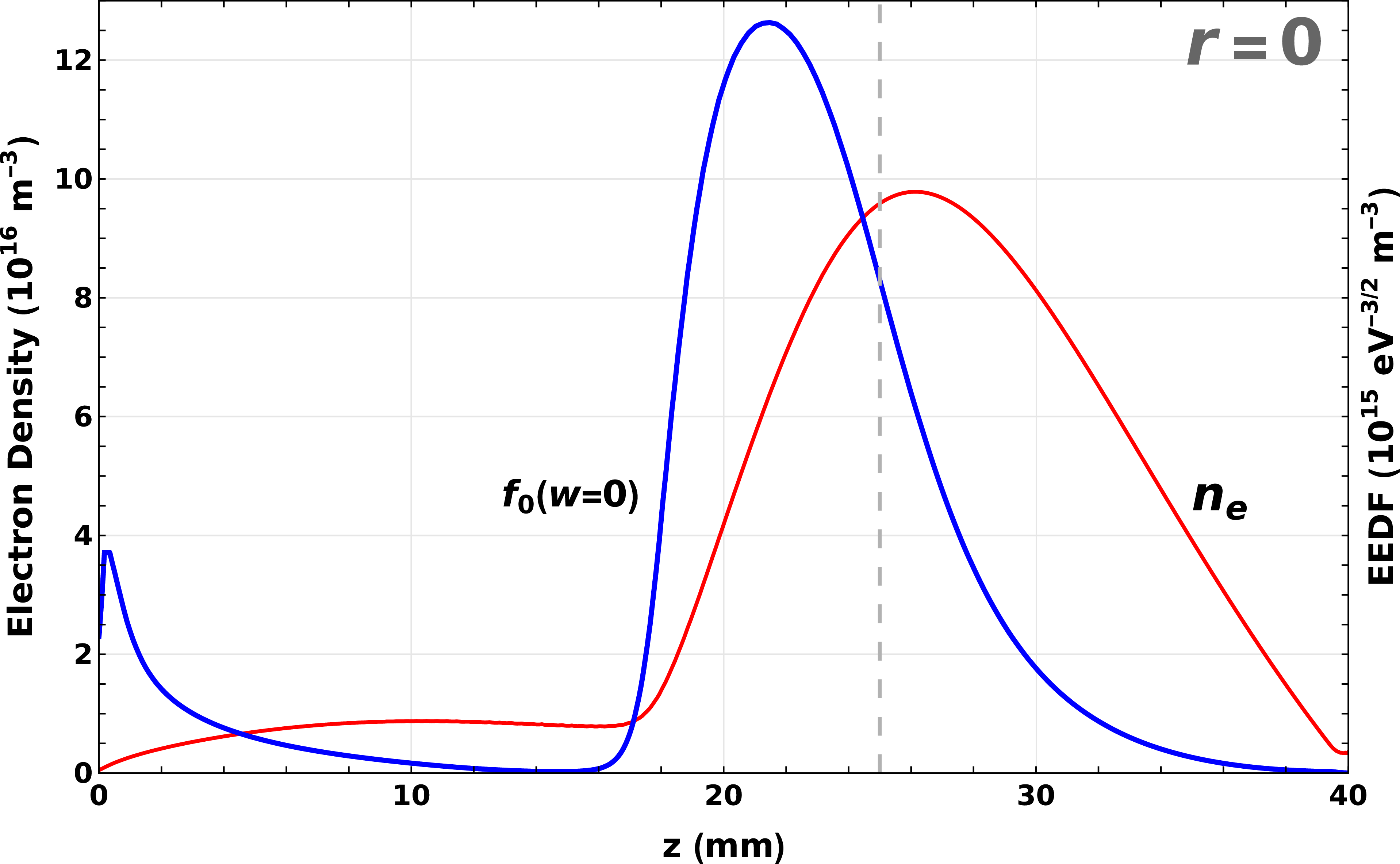
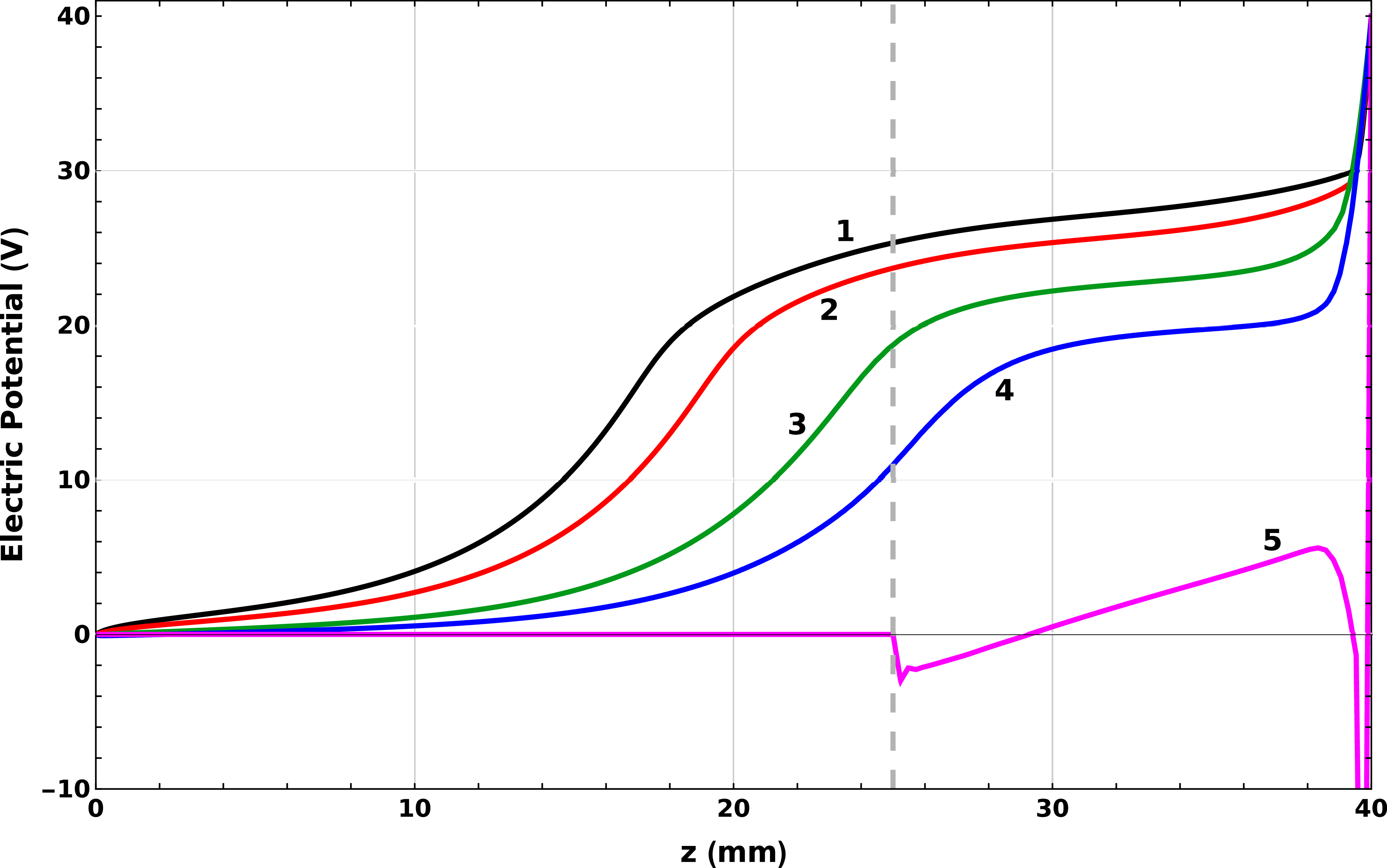
Figure 1 shows two-dimensional distributions of the electron density
 $n_e$
and EDF at zero kinetic energy
 $ f_0 |_{w=0}$
, figure 2 shows their axial profiles and figure 3 shows longitudinal profiles of the electric potential
 $\varphi$
for different values of radial coordinate
 $r$
. It can be seen from these figures that at the open part of the discharge, at the discharge axis, both
 $n_e$
and
 $ f_0 |_{w=0}$
decrease towards the anode and
 $\varphi$
increases towards the anode. Thus, both criteria (1.3) and (1.4) are fulfilled and an EDF inversion should occur in this area.
Two-dimensional profiles of the electron density
 $n_e$
and EDF at zero kinetic energy
 $f_0(w=0)$
. The white isolines divide the range of values from zero to the maximum value into 10 equal intervals.

Axial profiles of the electron density
 $n_e$
and EDF at zero kinetic energy
 $f_0(w=0)$
. The vertical dashed line shows the HC right boundary.

Longitudinal profiles of the electric potential
 $\varphi$
for different values of radial coordinate
 $r$
:
 ${r_1} = 0$
(1),
 ${r_2} = R/2$
(2),
 ${r_3} = 0.8R$
(3),
 ${r_4} = 0.9R$
(4) and
 ${r_5} = R$
(5).

Plots of
 ${f_0}( {z,w})$
for
 $z_1$
= 20 mm (1),
 $z_2$
= 24 mm (2),
 $z_3$
= 28 mm (3),
 $z_4$
= 32 mm (4) and
 $z_5$
= 36 mm (5) on the discharge axis (
 $r = 0$
).

Figure 4 shows
 $f_0(z, r=0, w)$
for different values of the axial coordinate
 $z$
. As expected, in the region of decreasing electron density
 $z \gt 25\,\text{mm}$
, where conditions (1.3) and (1.4) are satisfied, an inversion of the EDF in the region of low energies can be observed. In this case, as the anode is approached, the width of this region in the energy scale increases with a decrease in the electron density.
To analyse and explain the obtained result, we recall that under these conditions, the condition of non-locality
 $\lambda _\epsilon \gt L$
is satisfied. Therefore the argument of the EDF is the the total energy
 $\varepsilon = w - e \varphi$
(Tsendin Reference Tsendin1995) which is an integral of motion. This means that different groups of electrons preserve the total energy and do not ‘mix’ due to collisions. Figure 5 shows the same EDF as in figure 4 as a function of the total energy
 $\varepsilon$
.
The EDF as a function of the total energy
 $\varepsilon$
. The notations are the same as in figure 4. The dotted vertical lines correspond to
 $w=0$
.

It can be seen from figure 5 that there is an EDF inversion in the total energy range
 ${\varepsilon _2} \leqslant 16\,{\text{eV}}$
for
 $z \gt z_2$
. Similar to figure 4, when approaching the anode, the width of this region increases and the electron density decreases. However, the EDF inversion starts with approximately the same
 $\varepsilon _2$
. In other words,
 $( {{z_2},{\varepsilon _2}})$
on the phase plane
 $( {z,\varepsilon } )$
is a boundary point, from which the EDFs decrease towards both higher and lower energies. In the total energy scale, the EDFs in figure 5 have almost the same behaviour. However, the considered case is different from the classical Holstein–Tsendin model (Tsendin Reference Tsendin1995) which is realised for the trapped electrons. In this case, after averaging over the region of phase space accessible to electrons, the EDF becomes a function of only one variable
 $\varepsilon$
. In the considered case, due to the loss of electrons on the anode, the absolute values of the EDF decrease and a small (of the order of
 $L/{\lambda _\epsilon } \lt \,\,1$
) deformation of the energy dependence of the EDF occurs. Therefore, the EDFs of these electrons are always a function of two variables (
 $( {z, w} )$
or
 $( {z, \varepsilon })$
).
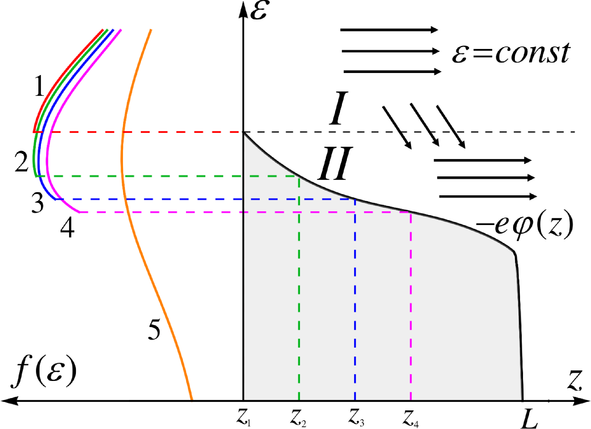
Figure 6 explains the formation of the inversion of the non-local EDF in the open part of the HC discharge. This figure is constructed using the aforementioned simulation data. The right part of the figure shows the calculated dependence of the potential
 $e\varphi ( z )$
on the point
 $z_1$
in figure 4, corresponding to the maximum plasma density. Point
 $z = L$
is the anode, which potential is set to zero. Since the kinetic energy of the electron
 $w = 0$
on the curve of the potential dependence
 $\varepsilon = -e\varphi ( z )$
, there are no electrons below this curve (darkened one). At
 $L \lt {\lambda _\epsilon }$
, non-local electrons move to the anode on the phase plane along the horizontal straight lines (black arrows in figure 6) while their total energy
 $\varepsilon$
is conserved. The initial value of the potential
 $e\varphi ( {{z_1}} )$
(black dotted horizontal line) divides the phase plane
 $( {z,\varepsilon })$
into two regions: the upper I where
 $\varepsilon \gt - e\varphi ( {{z_1}} )$
and the electron flux
 $\varPhi$
from the HC exist, and the lower II where the generation of charges does not occur. In the absence of inelastic collisions in region II, only electrons from zone I can enter due to their deceleration in elastic collisions. Therefore, in the non-local mode (
 $L \lt {\lambda _\epsilon }$
), the maximum of the EDF will be near the total energy
 $\varepsilon =-e\varphi ({z_1})$
, so that further from the anode, it will decrease towards higher and lower energies. This indicates that an inverse EDF will be observed. The left part of figure 6 shows the EDF dependencies calculated in this study (cf. figures 4 and 5), which confirms the aforementioned conclusions.
Formation of the EDF inversion in the open part of the HC discharge.

This consideration can be supplemented by the following analytical model. In region II for kinetic energies below the helium excitation threshold of 19.8 eV, the kinetic equation (2.1) can be written as
 \begin{align} \frac {\partial }{{\partial z}}\left ( {D\frac {{\partial {f_0}}}{{\partial z}}} \right ) + \frac {\partial }{{\partial \varepsilon }}\left ( {V\,{f_0}} \right ) = 0, \end{align}
where
 $D = \gamma w \lambda /3$
and
 $V = {w^{3/2}}\delta \,{\nu _a}$
are the spatial diffusion and ‘friction force’ coefficients, respectively. With a simplifying assumption that the coefficients
 $D$
and
 $V$
are constants (at some vicinity of the
 $\varepsilon = {\varepsilon _0}$
line on the phase plane), equation (2.4) is reduced by replacing of variable
 $t = {\varepsilon _0} - \varepsilon$
to the heat (or diffusion) equation, which has the following known fundamental solution:
 \begin{align} g\left (z,t\right ) = {\left ( {4\pi \left ( {D/V} \right )t} \right )^{ - 1/2}}\exp \left ( { - V\,{z^2}/\left ( {4D\,t} \right )} \right ). \end{align}
Thus, the function
 $G(z, \varepsilon )=g(z-z_0, \varepsilon _0-\varepsilon )$
is a solution of (2.4) with the initial condition
 $G(z, \varepsilon _0)=\delta (z-z_0)$
in the
 $\varepsilon \lt {\varepsilon _0}$
region. This solution decreases with the distance from the
 $\varepsilon =\varepsilon _0$
line on the phase plane
 $(z, \varepsilon )$
at
 $\varepsilon _0 - \varepsilon \gt (V/D)(z-z_0)^2 /2$
. In the considered situation, electrons can enter zone II only from zone I (see figure 6). Accordingly, the solution of kinetic equation (2.4) in zone II is a superposition of the solutions
 $g(z-z_0, \varepsilon _0-\varepsilon )$
for all points
 $z_0$
of the boundary
 $\varepsilon =\varepsilon _0$
:
 \begin{align} {f_0}\left ( {z,\,\varepsilon } \right ) = \int \limits _{z_1}^L {{f_0}\left (z_0, \varepsilon _0 \right ) g\left ( z - z_0, \varepsilon _0 -\varepsilon \right )\,{\rm d}{z_0}} . \end{align}
Thus, solution (2.6) decreases with increasing distance from the boundary
 $\varepsilon = {\varepsilon _0}$
. To make the behaviour of solution (2.6) more clear, we note that for the case
 $f_0(z_0, \varepsilon _0)=1$
,
 $z_1 =z-h$
and
 $L=z+h$
(where
 $h$
is a small length increment), (2.6) yields
 $f_0=\text{erf}(V h /\sqrt {4 D (\varepsilon _0-\varepsilon )}) \sim (\varepsilon _0-\varepsilon )^{-1/2}$
when
 $\varepsilon _0-\varepsilon$
is large enough. Consequently, in zone II,
 ${f_0}( {z,\varepsilon })$
increases with the increase of
 $\varepsilon$
, which explains the inversion of the EDF in this zone.
A similar approach to constructing a solution as a superposition of fundamental solutions like (2.5) can be extended to spatially two- and three-dimensional cases.
Note that the considered analytical model with solution (2.6) is not equivalent to criterion (1.3) because the inequality (1.3) gives a condition for the EDF inversion at zero kinetic energy
 $w=0$
and solution (2.6) provides an inversion in some neighbourhood of the
 $\varepsilon =\varepsilon _0$
line of the phase plane
 $(z,\varepsilon )$
. However, in the near-anode region of a glow discharge, the EDF inversion should be present in the whole region
 $\varepsilon \lt \varepsilon _0$
(region II in figure 6) and, thus, both approaches should give the EDF inversion.
The results of an experimental study of a HC discharge in helium are published in Astafiev et al. (Reference Astafiev, Kudryavtsev, Bogdanov and Yuan2025). That paper investigates a HC glow discharge in helium in a discharge chamber with the same geometry as in our paper. The results of this paper qualitatively correspond to those of the experimental study. Specifically, the potential on the discharge axis increases monotonically towards the anode, while the plasma density decreases. Unfortunately, direct attempts to measure the EDF using the classical method of recording the second derivative of the probe current (Zhou et al. Reference Zhou, Gorqid, Sun, Astafiev, Kudryavtsev, Yao, Gong, Nie, Zhou and Yuan2026a , Reference Zhou, Wang, Saifutdinov, Saifutdinova, Yao, Nie, Zhou and Yuan2026b ) do not provide an accurate answer to the EDF shape at low energies, since near the space potential, the probe I–V characteristic is inevitably distorted due to the finite resistance of the near-probe space charge layer and the effect of electron flow to the probe.
3. Conclusion
The theoretical analysis and numerical modelling show the fundamental possibility of creating an inverse EDF in the near-anode non-local plasma of a HC glow discharge.
By solving the unsimplified Boltzmann kinetic equation, inverse EDFs are determined, and the physical mechanisms of their formation under the studied conditions are analysed.
Based on the results of the numerical modelling and theoretical analysis, the following procedure for searching for inverse EDFs is recommended:
(1) The objects of research are spatially inhomogeneous media with a non-local EDF. When searching for inverse EDFs, attention should be first paid to the near-anode plasma of HC discharges, to the inhomogeneous PC of the discharge and to the two-chamber designs of inductively coupled plasma and capacitively coupled plasma discharges, where plasma is generated in the first chamber and diffuses into the second, ballast chamber.
(2) Based on the results of the heuristic analysis, a set of potential media with possible EDF inversion is taken into consideration. Based on the fluid modelling, the regions where the approximate criterion is met are selected.
(3) For the final determination of the regions of the EDF inversion, the unsimplified kinetic equation is solved and recommendations for experimental search are provided.
Thus, in this work, based on the proposed novel approach for creating an inverse EDF, practical recommendations for its experimental detection with an indication of specific conditions in a HC glow discharge are developed.
Acknowledgements
Editor Won Ho Choe thanks the referees for their advice in evaluating this article.
Funding
This work was supported by the National Natural Science Foundation of China (nos. 12505238 and U2541210), Natural Science Foundation of Heilongjiang Province of China (no. YQ2025A005) and Heilongjiang Graduate Excellence Funding Program (no. LJYXL2023-035).
Declaration of interests
The authors report no conflict of interest.

 ne
 f0(w=0)
 ne
 f0(w=0)
 φ
 r
 r1=0
 r2=R/2
 r3=0.8R
 r4=0.9R
 r5=R

 f0(z,w)
 z1
 z2
 z3
 z4
 z5
 r=0

 ε
 w=0

 Open access

