

I. INTRODUCTION
Long-term evolution (LTE) operation was recently introduced [1] in mobile devices, and therefore, their internal antennas should cover the LTE band, which includes the LTE700, LTE2300, and LTE2500 bands. In other words, the internal antenna embedded in these mobile devices should provide two wide operating bands (at least the bands 698–960 and 1710–2690 MHz) to cover the three LTE bands and five wireless wide area network (WWAN) bands (GSM850/900/1800/1900/UMTS). However, it has been a challenge to achieve dual-wideband operation with the small low-profile embedded antenna. Many laptop computer and tablet computer antennas have been designed to cover eight-band LTE/WWAN operation [Reference Wong and Tsai2–Reference Wong and Chen13]. In general, most of these antennas are arranged at the top edge of the display ground plane and have a height exceeding 10 mm. Moreover, with the development of laptop computers with metal covers, the positioning of the antennas at the top edge of the display ground plane is not appropriate. Therefore, the concept of hinge antennas, which are positioned in a narrow space at the hinge of the metal covers, has been proposed [Reference Chen and Wong14, Reference Chang and Liao15]. In particular, the antenna reported in [Reference Chen and Wong14] is designed to cover LTE/WWAN operation in a large antenna size of 71.5 × 6.5 × 3.5 mm3. It turns out that the antenna efficiency is poor due to the antenna surrounded by metal planes. Printed planar antennas covering the LTE/WWAN operating bands for wireless universal serial bus (USB) dongle applications have also been developed [Reference Ban, Chen, Sun, Li and Guo16, Reference Ban, Chen, Ying, Li and Wu17]. Wireless data can be received and transmitted anytime and anywhere by using a wireless USB dongle device attached to laptops. However, users may forget to carry the additional belongings that make some troubles and inconvenient, which render USB dongle devices unpopular and unattractive. To solve this problem, we proposed a small embedded LTE/WWAN antenna that can be installed in a clearance region of the keyboard ground plane. However, it is really a challenge to design an antenna surrounded by metal material with good antenna efficiency.
In this present, we successfully designed an embedded coupled-fed loop antenna integrated with the keyboard ground plane in a laptop computer. The proposed antenna is installed on a notched region (size 40 × 8 mm2) of the keyboard ground plane at a distance of 10 mm from the laptop computer hinge. The location can be plugged into a USB dongle device. By disposing the antenna in a region adjacent to the laptop computer hinge, the proposed antenna not only can contribute its modes but also excite the modes of hinge slot between the display ground plane and the keyboard ground plane to enhance the antenna bandwidth. The antenna design of integrating metal environment, the antenna can have small size and good antenna efficiency. The proposed antenna comprises a hook-shaped strip and a shorted strip, which together form a coupled-fed loop that not only has a compact size when printed on a 0.8-mm-thick FR4 substrate 40 × 8 mm2 in but also provides eight-band LTE/WWAN operation. This paper details the operating principle of the proposed antenna. The fabricated antenna was tested, and the test results are presented and analyzed.
II. PROPOSED ANTENNA
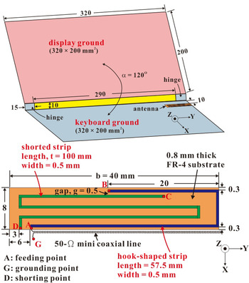
The proposed coupled-fed loop antenna was installed on a notched region (40 × 8 mm2) of the keyboard ground plane, and it is shown in Fig. 1. A laptop computer with an angle of 120° between its upper metal cover and its base metal cover was considered, and both covers were joined by two metal hinges. Each metal cover was a metal plate with dimensions of 320 × 200 mm2 used for simulating a 13-inch display panel and a keyboard panel. The two metal hinges were placed symmetrically at the two edges of a side of the metal covers to form a hinge slot (yellow region). The proposed coupled-fed loop antenna has a simple structure that can be easily printed on a 0.8-mm-thick FR4 substrate with a relative permittivity of 4.4 and a loss tangent of 0.024. The proposed antenna was installed on a notched region (40 × 8 mm2) of the keyboard ground plane at a distance of 10 mm from the laptop computer hinge. The location is probably plugged into a USB dongle device. The coupled-fed loop comprised a hook-shaped strip and a shorted strip. The hook-shaped strip and shorted strip had a width of 0.5 mm, a length of 57.5 mm, and 100 mm, respectively. A coupling gap of 0.5 mm was designed to provide sufficient capacitive coupling between the two strips for achieving good excitation of the quarter-wavelength coupled-fed loop mode. A small coupling gap of 0.3 mm was maintained between the hook-shaped strip and the keyboard ground plane to provide a coupling current for exciting the resonant modes of the hinge slot. A 50-Ω mini coaxial line was employed to excite the proposed antenna at the feeding point A through its central conductor, and point G in the keyboard ground plane was grounded through the outer grounding sheath of the antenna. Point D in the keyboard is the shorting point of the shorted strip.
Geometry of the proposed coupled-fed loop antenna for use in a laptop computer.

With this design, the proposed antenna not only generates the resonant modes of the coupled-fed loop but also excites the resonant modes of the hinge slot to widen the operating bandwidths. The proposed antenna was installed on a notched region, which is surrounded by the keyboard ground plane, and it could provide two wide operating bands to achieve eight-band LTE/WWAN operation covering the required bands (698–960 and 1710–2690 MHz).
III. RESULTS AND DISCUSSION
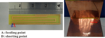
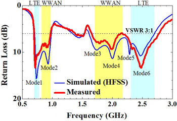
Figure 2 shows the fabricated prototype of the proposed antenna. The measured and simulated return losses of the antenna are presented in Fig. 3. The measured results accord with the simulated results. The simulated results were obtained using the full-wave electromagnetic field simulator HFSS (version 15) [18]. The measured impedance bandwidths defined by a voltage standing wave ratio of 3:1, which is widely used for internal WWAN and LTE antenna design specifications, were 270 MHz (695–965 MHz) and 1120 MHz (1680–2800 MHz) for the lower and upper bands, respectively. The proposed antenna could operate in two wide operating bands covering the LTE700/GSM850/900 and GSM1800/1900/UMTS/LTE2300/2500 bands. These two wide operating bands consist of six resonant modes corresponding to the coupled-fed loop and the hinge slot. Modes 1, 3, and 5 correspond to the coupled-fed loop, and Modes 2, 4, and 6 correspond to the hinge slot.
Photographs of the fabricated prototype.

Measured and simulated return loss of the proposed antenna.

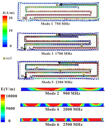
To further identify the contribution of each excited mode, the simulated surface current distributions in the metal strip at 750, 1700, and 2300 MHz (Mode 1, Mode 3, and Mode 5) and electric field distributions in the hinge slot at 900, 2000, and 2500 MHz (Mode 2, Mode 4, and Mode 6) were examined for the proposed antenna (Fig. 4). Clearly, at 900 MHz, the quarter-wavelength mode of the coupled-fed loop is excited. At 2000 and 2500 MHz, the higher-order resonant modes of the coupled-fed loop are excited. Furthermore, at 900 MHz, the half-wavelength mode of the hinge slot (see the strong electric fields in the middle section of the closed slot) is excited. At 2000 and 2500 MHz, the electric field distributions show the excitation of higher-ordered modes of the hinge slot. These excitations confirm that Modes 1, 3, and 5 correspond to the coupled-fed loop, and Modes 2, 4, and 6 correspond to the hinge slot.
Simulated surface current distributions in the metal strip at 750, 1700, and 2300 MHz and electric field distributions in the hinge slot at 900, 2000, and 2500 MHz for the proposed antenna.

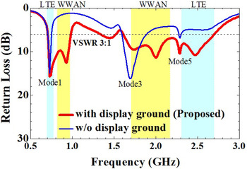
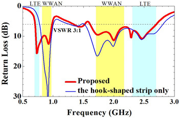
Figure 5 shows the simulated return loss of the proposed antenna with and without the display ground plane. Clearly, Modes 2, 4, and 6 have disappeared, because removing the display ground plane results in the absence of the hinge slot structure. Figure 6 shows the simulated return loss of the proposed antenna, and only the case of the hook-shaped strip is shown. Obviously, in this case, the bandwidth in the upper band cannot cover the LTE700 operation band because Mode 1, which corresponds to the coupled-fed loop, cannot be excited.
Simulated return loss of the proposed antenna with and without the display ground plane.

Simulated return loss of the proposed antenna and the case of the hook-shaped strip.

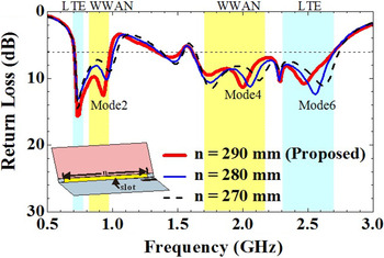
Figure 7 shows the simulated return loss as a function of the length n of the hinge slot for the proposed antenna. Results of the simulated return loss for lengths ranging from 270 to 290 mm are presented. When the length is increased, Modes 2, 4, and 6 shift to lower frequencies. Simultaneously, Modes 1, 3, and 5 change only slightly in the matching. Therefore, clearly, Modes 2, 4, and 6 correspond to the hinge slot.
Simulated return loss of the proposed antenna as a function of the length n of the hinge slot.

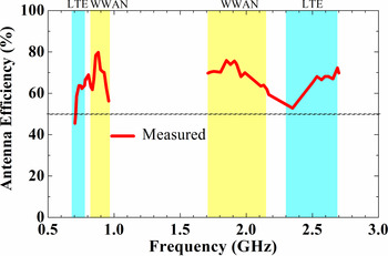
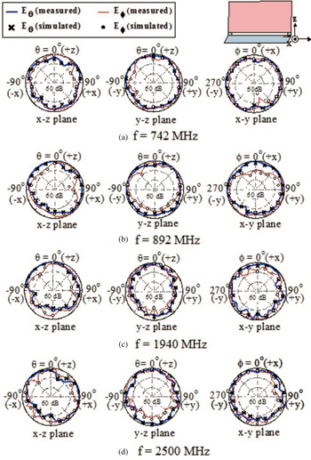
The measured antenna efficiency, which includes the mismatch loss, is shown in Fig. 8. The measured antenna efficiency in a far-field anechoic chamber reached approximately 45–80% in the lower band and approximately 52–75% in the upper band, and these efficiencies are acceptable in mobile communication applications. The measured and simulated radiation patterns of the proposed antenna at 742, 892, 1940, and 2500 MHz are shown in Fig. 9. The frequencies of 742, 892, 1940, and 2500 MHz are close to the central frequencies of the lower and upper bands of the LTE/WWAN operating bands. For each frequency, the radiation patterns in three planes are shown. The measured radiation patterns agree well with each other. Some variations are visible in the lower band, and greater variations are evident in the upper band. These variations are related to the excited surface current distributions. In general, no large variations in the radiation patterns are observed. Thus, stable radiation patterns were obtained for the proposed antenna for LTE/WWAN operation.
Measured antenna efficiency, including the mismatch loss.

Measured and simulated radiation patterns of the proposed antenna at 742, 892, 1940, and 2500 MHz.

IV. CONCLUSION
A novel small coupled-fed loop antenna integrated with the surrounding keyboard ground plane in a laptop computer is proposed. The antenna achieves LTE/WWAN dual-wideband operation in the 698–960 and 1710–2690 MHz bands. Moreover, the proposed antenna can not only be integrated with the surrounding keyboard ground plane but also excite several resonant modes of the hinge slot to widen the operating bandwidths. The proposed antenna has a compact size when printed on a 0.8-mm-thick FR4 substrate 40 × 8 mm2 in size and provides eight-band LTE/WWAN operation. The measured antenna efficiency is approximately 45–80% in the lower band and approximately 52–75% in the upper band. Experimental results showed that the fabricated antenna had favorable radiation characteristics.
ACKNOWLEDGEMENT
This work was supported by the Ministry of Science and Technology, Taiwan, R.O.C. under grant NSC 102-2218-E-606-002-.
 Shu-Chuan Chen received the B.S. and M.S. degrees in electrical engineering from Chung-Cheng Institute of Technology, National Defense University, Taoyuan, Taiwan, and the Ph.D. degree in electrical engineering from National Sun Yat-sen University, Kaohsiung, Taiwan, in 1998, 2004, and 2012, respectively. Since 2012 she has served in the department of electrical and electronic engineering, Chung Cheng Institute of Technology, National Defense University, (CCIT, NDU), Taoyuan, Taiwan. She also holds over 20 patents, including USA, Taiwan, and China patents. Her main research interests are in internal antennas for mobile communication devices, especially for small-size multiband antennas in the mobile phones.
 Yun-Tsan Lee received the M.S. degree in electrical and electronic engineering, Chung Cheng Institute of Technology, National Defense University, (CCIT, NDU), Taoyuan, Taiwan. His main research interests are in internal antennas for mobile communication devices.
 Po-Wei Wu received the B.S. degree in Electrical Engineering, Feng Chia University, Taichung City, Taiwan. His main research interests are in internal antennas for mobile communication devices.