I. INTRODUCTION
Thermomigration (TM) is a cross effect or interaction between heat flow and mass flow that occurs under a temperature gradient. Reference Chen, Hsiao, Chang, Ouyang and Tu1 With the continuous shrinking of interconnection in three-dimensional (3D) packaging applications, temperature gradient may exist in solder joints during soldering or subsequent service process due to the differences in thermal conduction and dissipation among chips, solder bumps, and the substrate. Reference Zhong, Huang, Ma, Dong, Wang and Zhao2 Under a certain temperature gradient, TM could be induced across the solder layer, driving mass atoms to diffuse toward or against the cold end. Reference Zhao, Zhong, Dong, Huang, Ma and Wong3–Reference Hsiao and Chen6 The TM-induced redistribution of elements in the liquid solder would greatly affect the interfacial reaction, i.e., the growth of intermetallic compounds (IMCs) and the dissolution of under bump metallization (UBM) and further cause substantial reliability issues of interconnection. Thus, TM has become a serious reliability concern in 3D packaging.
Eutectic Sn–9Zn (wt%) solder has been recognized as a promising candidate for replacing eutectic Sn–37Pb solder in electronic packaging technology due to its relatively moderate melting point of 198.5 °C compared with those of other lead-free solders. Reference Pandey, Tiwary and Chattopadhyay7,Reference Liu, Zhang, Ma and Suganuma8 In addition, Ni thin film is commonly used as a diffusion barrier layer in UBMs, as well as in several types of surface finishes for components and printed circuit boards since Ni has a much slower reaction rate with an Sn-based solder than that of Cu. Reference Yang, Yang and Ouyang9,Reference Chou, Chen and Chang10
Generally, when Ni is reacted with Sn at a temperature relevant to soldering, only Ni3Sn4 is formed at the interface. Reference Ho, Yang and Kao11 While for Zn-containing solder/Ni joints, Ni–Zn based IMCs are the dominant reaction products because Zn is more chemically active than Sn. Reference Chou, Chen and Chang10 However, the content of Zn in liquid solder will significantly decrease with the prolonged reaction time because of the growth of Zn-containing interfacial IMCs, especially in small size solder joints, which inevitably affects the reaction process. Several studies have reported the interfacial reactions between Sn–xZn solders and Ni substrates during isothermal reflow, indicating that the Zn content greatly affects the formation of interfacial IMCs. Wang et al. Reference Wang and Chen12 found that when the Zn content was higher than 5 wt%, a uniform layer of Ni5Zn21 was formed and grew continuously with a reaction time; when Zn content was lower than 2 wt%, the initial reaction product was (Ni,Zn)3Sn4, and it transformed into Ni3Sn4 with a prolonged reflow time. In their later study, Reference Wang, Chen and Lai13 they reported that the initial interfacial IMC was Ni3Sn4 when the Zn content was less than 0.3 wt%, while the initial IMC was the τ phase (about Sn–35 at.% Ni–20 at.% Zn) when the Zn content was above 0.4 wt%. Zhu et al. Reference Zhu, Liu, Wang, Ma and Jin14 studied the interfacial reactions between Sn–Zn solders (with 8 at.% Zn, 35 at.% Zn, and 60 at.% Zn) and Ni substrates and found that Ni5Zn21 was the only phase formed at the interface and the growth rate increased with the Zn content. Similar preferential formation of Zn-containing IMCs was also reported in Sn–Zn/Cu and Sn–Zn/Ag systems. Reference Li, Chan, Zhang and Yung15,Reference Jao, Yen, Lin and Lee16
In our previous studies, Reference Zhong, Zhao, Ma, Dong and Huang17,Reference Zhao, Deng, Zhong, Huang and Ma18 we investigated the TM of Cu/Sn–xZn/Cu and Ni/Sn–9Zn/Ni joints and found that Zn addition could greatly inhibit the TM-induced substrate dissolution and also result in the abnormal evolution of IMCs between cold and hot ends. In addition, the Zn content is usually less than 9 wt% in some ternary or quaternary Zn-bearing solders, and different types of initial IMCs are formed between Sn–xZn solders and the Ni substrate. As the type and thickness of interfacial IMCs can greatly affect the reliability of solder joints, it is quite necessary to fully understand the effect of TM behavior on IMC evolution in Ni/Sn–xZn/Ni joints. The purpose of this study is to investigate the interfacial reactions of Ni/Sn–xZn/Ni joints under a temperature gradient and reveal the combined effect of Zn content and TM on the evolution of IMCs at both hot-and cold-end interfaces.
II. EXPERIMENTAL
Ni/Sn–xZn/Ni (x = 1, 5, 9 wt%) joints were prepared from pure Ni (99.99%) plates and Sn–xZn solders by immersion soldering. The matched surfaces of two Ni plates were carefully ground, polished, and cleaned in ethanol. The gap between the two Ni plates was controlled by stainless spacers to achieve a designed solder layer thickness of about 100 µm. After the polished faces were aligned and fixed, the whole configuration was immersed into a solder bath at 250 °C for 30 s. Then the specimens were cooled immediately in water to room temperature and cut into small individual solder joints. The solder joints were then ground and polished to a final size of (10 mm Ni/100 μm solder/2 mm Ni) × 500 × 200 μm.
The TM experiments were conducted by reflowing the solder joints on a hot plate at 330 °C for different durations, which was reported in detail in the previous study. Reference Zhong, Zhao, Ma, Dong and Huang17 The solder joints were attached on a specially designed fixture through silicone grease which could keep the relative positions of the joints during reflow. After reflow, the solder joints were quenched in water immediately to preserve the status undergoing TM. The morphology and composition of the IMC phases were observed and identified successively by scanning electron microscopy (SEM; Zeiss Super 55, Carl Zeiss AG, Oberkochen, Germany), energy dispersive X-ray spectroscopy (EDX), and electron probe micro analyzer (EPMA-1600, Shimadzu Corp., Kyoto, Japan). The average thicknesses of the IMC layers were measured using image processing software.
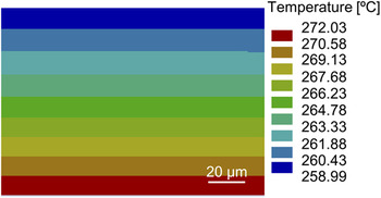
The temperatures of certain positions on the Ni substrates close to the top interface (i.e., the cold end) and the bottom interface (i.e., the hot end) were measured using Omega type K thermocouples with a diameter of 0.32 mm. The measured temperature was 256.8 °C and 280.3 °C at the cold and hot ends, respectively. The temperature distribution in the liquid solder layer was simulated by finite element method (FEM) using a steady-state thermal model and a hexahedron mesh. Since the Sn content was higher than 90 wt% in all the solder joints, the physical parameters of molten Sn were used for the Sn–xZn solders in the FEM simulation. The thermal conductivities of Ni, molten Sn, and silicone grease used for the simulation were 90.7, 30.7, and 4.5 W/m K, respectively. The combined heat transfer coefficient of convection and radiation was set to be 65 W/m2 K. Reference Zhao, Zhong, Huang, Ma and Dong19 The simulated temperatures of the Ni substrates agreed well with the values measured by the thermocouples at the same positions. Figure 1 shows the simulated temperature distribution in the solder layer. Thus, a temperature gradient of 1304 °C/cm existed across the liquid solder layer. The average temperature of 265 °C was regarded as the working temperature of the reflow process. It is noted that the solder layer thickness was found to have little effect on the simulated temperature gradient in this study.
Simulated temperature distribution in the solder layer during reflow under temperature gradient.

III. RESULTS AND DISCUSSION
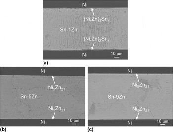
Figure 2 shows the SEM images of the as-soldered Ni/Sn–xZn/Ni joints. For Ni/Sn–1Zn/Ni joint, as shown in Fig. 2(a), a continuous thin layer of IMC with an average thickness of 1.02 μm formed at each interface. The IMC composition was identified as Sn–33.57 at.% Ni–9.76 at.% Zn by EDX analysis, i.e., (Ni,Zn)3Sn4. For Ni/Sn–5Zn/Ni and Ni/Sn–9Zn/Ni joints, as shown in Figs. 2(b) and 2(c), the IMCs observed at all the interfaces were identified to be Ni5Zn21, and the average IMC thicknesses were 0.79 and 0.81 μm, respectively.
Cross-sectional SEM images of the as-soldered Ni/Sn–xZn/Ni joints: (a) Ni/Sn–1Zn/Ni, (b) Ni/Sn–5Zn/Ni, and (c) Ni/Sn–9Zn/Ni.

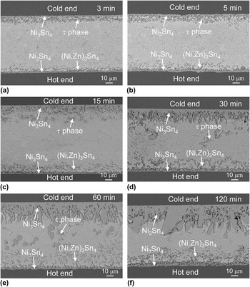
Figure 3 shows the cross-sectional SEM images of the Ni/Sn–1Zn/Ni joints after reflow under a temperature gradient for different durations. After reflow for 3 min, as shown in Fig. 3(a), the detachment of IMCs occurred at both interfaces. The composition of the granular detached IMCs at the cold end was identified as Sn–32.18 at.% Ni–21.09 at.% Zn, which should be a ternary τ phase according to the previous study. Reference Wang, Chen and Lai13,Reference Chen, Hsu, Chou and Hsu20 While at the hot end, the composition of the detached IMCs was Sn–28.15 at.% Ni–16.83 at.% Zn, i.e., (Ni,Zn)3Sn4. The detachment phenomenon was considered to be caused by the formation of a continuous Ni3Sn4 layer on the Ni substrate at each interface. Because the original (Ni,Zn)3Sn4 IMC at the interface was no longer in local thermodynamic equilibrium with the solder, this IMC spalled away to make room for the subsequent nucleation and growth of the new Ni3Sn4 IMC. Reference Chen, Yang, Tsai and Kao21 Wang et al. Reference Wang and Chen12 also found the detachment phenomenon of the Zn-containing IMC in the Sn–1Zn/Ni couple reacted at 250 °C for 15 min. The thickness of the Ni3Sn4 was 3.16 μm at the cold end and 2.16 μm at the hot end. It is also noted that the initial (Ni,Zn)3Sn4 IMC at the cold end had transformed into the τ phase, indicating that the TM of Zn atoms was toward the cold end. After reflow for 5 min, as shown in Fig. 3(b), the Ni3Sn4 layers at both interfaces continued to grow, with the thicknesses of 4.64 and 2.92 μm at the cold and hot ends, respectively. Meanwhile, the granular τ phase (Sn–31.19% Ni–22.96% Zn) near the cold end grew a bit larger due to the continuous TM of Zn toward the cold end. Hereafter, as shown in Figs. 3(c)–3(f), the Ni3Sn4 IMC grew very fast at the cold end (38.90 μm after 120 min) while relatively slow at the hot end (6.09 μm after 120 min), showing an increasingly asymmetrical growth behavior. Moreover, the τ phase tended to disperse into the solder matrix along with the fast growth of the cold-end Ni3Sn4 IMC toward the hot end and totally disappeared after a reflow for 120 min.
Cross-sectional SEM images of the Ni/Sn–1Zn/Ni joints after reflow under temperature gradient for: (a) 3 min, (b) 5 min, (c) 15 min, (d) 30 min, (e) 60 min, and (f) 120 min.

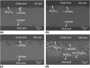
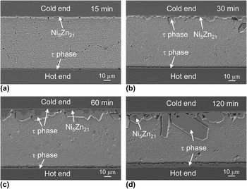
Figure 4 shows the cross-sectional SEM images of the Ni/Sn–5Zn/Ni joints after reflow under a temperature gradient for different durations. After reflow for 15 min, the initial Ni5Zn21 IMC at the hot end totally transformed into a continuous τ phase layer of 0.96 μm. While at the cold end, in addition to a thin Ni5Zn21 IMC layer near the Ni substrate, a large number of discontinuous τ phases were also detected on the solder side, with a total thickness of 3.24 μm. After reflow for 30 min, the τ phase kept growing to 4.02 μm at the hot end and to 9.42 μm at the cold end at the expense of Ni5Zn21 consumption, respectively. After reflow for 60 min, the thin Ni5Zn21 IMC layer at the cold end disappeared totally, leaving a thick continuous τ phase layer with a thickness of 13.48 μm. Meanwhile, the thickness of the τ phase at the hot end was only 4.69 μm. When the reflow time increased to 120 min, Ni3Sn4 IMC was formed at the τ phase/Ni interface at the cold end, resulting in partial detachment of the blocky τ phases from the interface, as indicated by the white oval in Fig. 4(d). A continuous Ni3Sn4 IMC layer and dispersive (Ni,Zn)3Sn4 particles were observed instead of the τ phase at the hot end. The thicknesses of the IMC layers were 27.15 and 4.02 μm at the cold and hot ends, respectively.
Cross-sectional SEM images of the Ni/Sn–5Zn/Ni joints after reflow under temperature gradient for: (a) 15 min, (b) 30 min, (c) 60 min, and (d) 120 min.

Figure 5 shows the cross-sectional SEM images of the Ni/Sn–9Zn/Ni joints after reflow under a temperature gradient for different durations. After reflow for 15 min, the interfacial IMC at the cold end remained as Ni5Zn21 with a thickness of 2.86 μm. At the hot end, however, EDX analysis indicated that the reaction product was a τ phase instead of the initial Ni5Zn21 IMC, and the thickness was only 0.92 μm. Obviously, asymmetrical growth and evolution of IMCs between the cold and hot ends occurred in all the Ni/Sn–xZn/Ni joints. After a reflow for 30 min, in addition to the Ni5Zn21 IMC, a thin τ phase layer and discontinuous τ phases were also formed at the Ni/Ni5Zn21 and Ni5Zn21/solder interfaces at the cold end, respectively, with a total IMC thickness of 5.72 μm. The τ phase at the hot end grew slowly to 1.37 μm. After a reflow for 60 min, both the Ni5Zn21 and τ phase IMCs at the cold end grew thicker and the total thickness was 14.23 μm. At the hot end, the τ phase was only 2.41 μm in thickness. Similar formation and growth behaviors of the τ phase were also observed at the cold end in our previous study. Reference Zhao, Deng, Zhong, Huang and Ma18 However, the τ phase is not typically formed at the Ni5Zn21/solder interface when isothermally reflowing Zn-bearing solders on Ni substrates. Reference Chou, Chen and Chang10,Reference Chiu, Wang and Chuang22 When the reflow time prolonged to 120 min, the cold-end IMCs which were 22.53 μm thick mainly consisted of a blocky τ phase with some Ni5Zn21 IMC islands. While at the hot end, the reaction product remained as the τ phase with a thickness of 6.82 μm.
Cross-sectional SEM images of the Ni/Sn–9Zn/Ni joints after reflow under temperature gradient for: (a) 15 min, (b) 30 min, (c) 60 min, and (d) 120 min.

It is noted that the consumption of the hot-end Ni substrates was more serious than that of the cold-end Ni substrates in all the solder joints regardless of the Zn content, as evidenced by the more uneven IMC/Ni interfaces at the hot end. The serious Ni consumption was caused by the additional temperature gradient during reflow. Then the dissolved Ni atoms as well as the Zn atoms in the liquid solder were continuously driven to diffuse toward the cold end, providing sufficient atomic fluxes for the formation and growth of the cold-end IMCs. As a result, asymmetrical IMC growth and transformation and Ni substrate dissolution were clearly observed between the cold and hot ends.
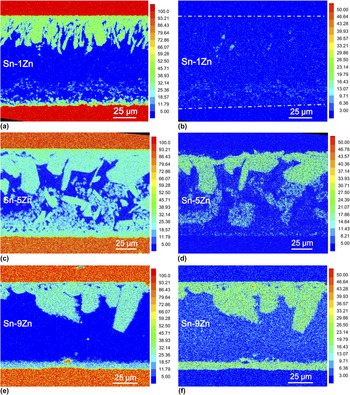
The above results revealed that the Zn content greatly affected the IMC evolution in Ni/Sn–xZn/Ni joints under a temperature gradient. EPMA was used to examine the elemental distribution in the solder joints which were slightly ground and polished once again after the SEM observation. Figure 6 shows the elemental distribution maps in the Ni/Sn–xZn/Ni joints after reflow under a temperature gradient for 120 min. For the Ni/Sn–1Zn/Ni joint, as the Zn-containing IMCs gradually detached from the two interfaces and Zn deposited as IMCs in the solder matrix, no Zn was detected in the interfacial IMCs at both cold and hot ends, as shown in Fig. 6(b), which was in consist with the EDX analysis. On this occasion, the interfacial IMCs were Ni-based, namely Ni3Sn4, as shown in Fig. 6(a). Moreover, the IMC at the cold end had a greater amount of Ni and a higher Ni concentration than that at the hot end, indicating that Ni migrates toward the cold end under a temperature gradient. It is noted that the profile of the IMCs did not match well between Figs. 3(f) and 6(a) due to the regrind and repolish process before the EPMA analysis.
Elemental distribution maps in the Ni/Sn–xZn/Ni joints after reflow under temperature gradient for 120 min: (a), (c), and (e) Ni, and (b), (d), and (f) Zn.

For the Ni/Sn–5Zn/Ni joint, the Ni distribution was similar to the Ni/Sn–1Zn/Ni case, as shown in Fig. 6(c). Little Zn was found in the hot-end IMC layer, and the detachment of blocky τ phases from the cold end and dispersive (Ni,Zn)3Sn4 particles from the hot end caused an uneven Zn distribution in the solder matrix, as shown in Fig. 6(d). Furthermore, a nonZn-containing Ni-based IMC layer (Ni3Sn4) was detected between the Zn-containing IMC layer (τ phase) and the Ni substrate at the cold end. The cold-end IMC contained higher Ni and Zn contents, indicating that both Ni and Zn were migrated toward the cold end under a temperature gradient. For the Ni/Sn–9Zn/Ni joint, the Ni and Zn distributions were similar to those in the Ni/Sn–5Zn/Ni joint. However, no IMC detachment occurred at both interfaces even after a reflow for 120 min, as shown in Figs. 6(e) and 6(f). The elemental distribution results demonstrated that both Ni and Zn atoms were forced to migrate toward the cold end under a temperature gradient, which resulted in the asymmetrical growth and evolution of the interfacial IMCs between the cold and hot ends.
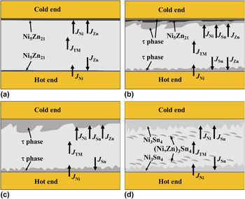
Figure 7 schematically illustrates the evolution of interfacial IMCs in the Ni/Sn–xZn/Ni joints under a temperature gradient. J TM represents the TM-induced atomic flux, and J Sn, J Ni, and J Zn represent Sn, Ni, and Zn atomic flux during reflow, respectively. When the Zn content is approximated to 9 wt% at the early stage, as shown in Fig. 7(a), Ni5Zn21 keeps growing at both cold and hot ends due to the sufficient supply of Zn which has a stronger affinity with Ni than Sn. Thus, Zn is the dominant diffusion species that maintains the interfacial IMCs as Ni5Zn21 during this stage. Besides, as Zn and Ni atoms continuously migrate toward the cold end, the Ni5Zn21 IMC at the cold end grows much faster than that at the hot end.
Schematics of interfacial IMC evolution in the Ni/Sn–xZn/Ni joints under temperature gradient: (a) early stage in Ni/Sn–9Zn/Ni, (b) early stage in Ni/Sn–5Zn/Ni, (c) late stage in Ni/Sn–5Zn/Ni, and (d) Ni/Sn–1Zn/Ni or Zn is lower than 1 wt%.

As the reaction undergoes, the Zn content in the liquid solder decreases to a low level, probably close to or lower than 5 wt%, under which the interfacial Ni5Zn21 IMCs become unstable, especially for the hot end. Meanwhile, Ni atoms could diffuse into the thin Ni5Zn21 IMC layers under a temperature gradient and also Sn under a chemical potential gradient. As a result, τ phase forms at both the hot and cold ends, as shown in Fig. 7(b). This IMC transformation occurs much quicker and more complete at the hot end than at the cold end. In addition, a thick τ phase is abnormally formed at the Ni5Zn21/solder interface at the cold end. During an isothermal reflow process, Ni atoms are hard to diffuse into the liquid solder as long as the Ni5Zn21 IMC layer exists, and thus the τ phase could only form at the Ni/Ni5Zn21 interface. However, in this study, massive Ni atoms diffuse to the cold end from the hot end under a temperature gradient, resulting in the formation of the τ phase not only at the Ni/Ni5Zn21 interface but also at the Ni5Zn21/solder interface. Indeed, the τ phase at the Ni5Zn21/solder interface is much thicker than that at the Ni/Ni5Zn21 interface and at the hot end.
With the continuous migration of Zn and Ni atoms toward the cold end, the τ phase maintains growing along with the consumption of Ni5Zn21 which is finally exhausted, as shown in Fig. 7(c). Although the τ phase becomes the dominant IMC at both interfaces, the cold-end τ phase has a much higher growth rate. As the Zn content further decreases to lower than 1 wt%, Sn and Ni become the dominant diffusion species through τ phase layers and then Ni3Sn4 IMCs form and grow at the τ phase/Ni interfaces, resulting in the detachment of the τ phase, as shown in Fig. 7(d). In a word, if we reflow the Ni/Sn–9Zn/Ni joints long enough, the interfacial IMC evolution should follow the Ni5Zn21 → τ phase → Ni3Sn4 along with the reflow time, and corresponding transformation at the cold end will markedly lag behind that at the hot end.
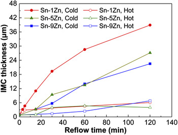
Figure 8 shows the thickness of the IMC layers at both cold and hot ends for the Ni/Sn–xZn/Ni joints as a function of the reflow time under a temperature gradient. For all Ni/Sn–1Zn/Ni joints and the hot end of the Ni/Sn–5Zn/Ni joint after a reflow for 120 min, only the thickness of Ni3Sn4 was considered since the Zn-containing IMCs had detached totally from the interface. As shown in Fig. 8, the cold-end IMC layer is obviously thicker than the hot end one in the same solder joint because of the continuous migration of Zn and Ni atoms toward the cold-end interface.
Thickness of the IMC layers at the cold and hot ends in the Ni/Sn–xZn/Ni joints as a function of reflow time under temperature gradient.

At the cold end, the thickness of the IMC layers increases against the Zn content under the same reflow time, i.e., higher Zn content can more effectively restrain the growth rate of the cold-end IMCs. This is due to the fact that a layered Zn-containing IMC at the hot end could significantly inhibit the consumption of the neighboring Ni substrate into the liquid solder and consequently reduce the TM-induced Ni atomic flux for the IMC growth at the cold end. Since a higher Zn content can postpone the transformation of Ni–Zn-based IMC into Ni–Sn-based IMC at the hot end, less consumption of the hot-end Ni substrate and TM-induced Ni atomic flux occurs in a higher Zn content solder joint. Consequently, a lower IMC growth rate is achieved at the cold end. In our previous study, we also found similar retardation of TM-induced Cu substrate consumption in Pb-free solder joints by Zn addition. Reference Zhong, Zhao, Ma, Dong and Huang17,Reference Zhao, Zhong, Huang, Dong, Wang and Ma23
At the hot end, the interfacial IMCs grow relatively slow. The hot end IMC in the Ni/Sn–1Zn/Ni joints tends to reach a certain critical thickness after it has transformed from the initial (Ni,Zn)3Sn4 to Ni3Sn4 with a prolonged reaction time, which may be attributed to the dynamic equilibrium between the chemical potential gradient and temperature gradient at the interface. Reference Zhao, Zhong, Huang, Ma and Dong24 In the Ni/Sn–5Zn/Ni joints, the τ phases grow slowly before 60 min. However, it detaches from the hot-end interface totally between 60 and 120 min, and a new interfacial IMC layer of Ni3Sn4 forms at the hot end. As a result, the IMC thickness after 120 min is smaller than that after 60 min because only the newly formed Ni3Sn4 layer is taken into account. In the Ni/Sn–9Zn/Ni joints, as the IMC at the hot end remains as the τ phase even after 120 min, its thickness continuously increases at a slow rate.
IV. CONCLUSION
Zn content significantly affected the interfacial IMC evolution in Ni/Sn–xZn/Ni joints reflowed under a temperature gradient. For Ni/Sn–1Zn/Ni joints, the initially formed (Ni,Zn)3Sn4 gradually detached from the two interfaces and transformed into the τ phase at the cold end while it remained as (Ni,Zn)3Sn4 at the hot end. Meanwhile, the newly formed Ni3Sn4 layer at the cold end grew much faster than that at the hot end. For Ni/Sn–5Zn/Ni and Ni/Sn–9Zn/Ni joints, the initially formed Ni5Zn21 IMC transformed into the τ phase quickly at the hot end while it was gradually consumed by the growth of the τ phases at both Ni/Ni5Zn21 and Ni5Zn21/solder interfaces at the cold end. Moreover, the τ phases in the Ni/Sn–5Zn/Ni joints detached totally from the hot end and partly from the cold end due to the formation of Ni3Sn4 at both interfaces. However, no Ni3Sn4 was observed in the Ni/Sn–9Zn/Ni joints even after a reflow for 120 min. Zn and Ni atoms continuously migrated toward the cold end under a temperature gradient, causing faster IMC growth at the cold end and a more prompt IMC transformation from Ni–Zn based to Ni–Sn based at the hot end. A higher Zn content could effectively restrain the growth of the cold-end IMC and the dissolution of the hot-end Ni substrate and postpone the IMC transformation at both cold and hot ends.
ACKNOWLEDGMENTS
This work was supported by the National Natural Science Foundation of China (Grant Nos. 51675080 and 51571049), the Dalian High-level Talents Innovation Support Program (Grant No. 2016RQ007), the Fundamental Research Funds for the Central Universities (Grant No. DUT17JC44), and the China Scholarship Council (Grant No. 201606065047).