


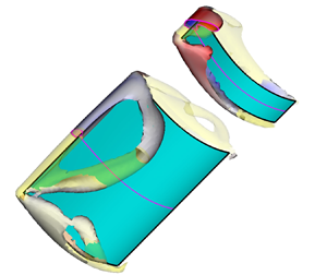



1. Introduction
The flow-induced motion of flexible bodies is an everyday observation, from moving leaves in the wind to animals flying and swimming. Flag flapping is a canonical example of such interaction that has drawn much interest over the past decades for its aerodynamic and energy harvesting applications (Shelley & Zhang Reference Shelley and Zhang2011; Yu, Liu & Amandolese Reference Yu, Liu and Amandolese2019). Another similar canonical configuration is the inverted flag in which the leading edge is free to interact with incoming flow, and the trailing edge is fixed. The inverted flag problem was first studied experimentally by Kim et al. (Reference Kim, Cossé, Huertas-Cerdeira and Gharib2013). They identified three distinct response modes of the structure due to its interaction with the flow: a stationary mode at low flow velocities, a two-sided flapping mode at intermediate flow velocities and a one-sided flapping or deflected mode at high flow velocities (Kim et al. Reference Kim, Cossé, Huertas-Cerdeira and Gharib2013; Sader et al. Reference Sader, Cossé, Kim, Fan and Gharib2016a; Gurugubelli & Jaiman Reference Gurugubelli and Jaiman2019; Ojo et al. Reference Ojo, Tan, Wang, Shoele and Erturk2019, Reference Ojo, Shoele, Erturk, Wang and Kohtanen2021; Park, Ryu & Sung Reference Park, Ryu and Sung2019). These modes emerge from the balance between vortex-generated forces and the elastic restoring force in the flag (Yu et al. Reference Yu, Liu and Amandolese2019), resulting in self-sustained vibrations at relatively low flow speeds. Later, three additional response modes, the buckled mode, small-amplitude asymmetric flapping mode and chaotic mode, were also identified (Goza, Colonius & Sader Reference Goza, Colonius and Sader2018; Tavallaeinejad et al. Reference Tavallaeinejad, Païdoussis, Salinas, Legrand, Kheiri and Botez2020c). The first two modes exist between the stationary and flapping modes, while the chaotic mode can occur between the flapping and deflected modes. The inverted flag configuration requires much lower critical flow velocity to reach a large amplitude vibration compared with the regular flag configuration, and this is key for its better performance in energy harvesting applications (Shoele & Mittal Reference Shoele and Mittal2016; Orrego et al. Reference Orrego, Shoele, Ruas, Doran, Caggiano, Mittal and Kang2017).
Previous studies have shown that, although heavy inverted flags with a low mass ratio ( $M^{*}\ll 1$) exhibit a self-sustained two-sided fluttering response, they are not necessarily governed by vortex-induced vibration because the resonant frequency of the flag is less than its vortex shedding frequency (Sader, Huertas-Cerdeira & Gharib Reference Sader, Huertas-Cerdeira and Gharib2016b; Tavallaeinejad et al. Reference Tavallaeinejad, Païdoussis, Legrand and Kheiri2020b). Instead, they are driven by self-excitation through a fluid elastic instability. This phenomenon was also observed in the experimental study of Tavallaeinejad et al. (Reference Tavallaeinejad, Païdoussis, Salinas, Legrand, Kheiri and Botez2020c), which suggests that momentum-induced aerodynamic forces govern the periodic fluttering motion. Also, it has been shown that inverted flags undergo self-sustained periodic fluttering for a wide range of
 $AR$, defined here as the width to length ratio (Sader et al. Reference Sader, Cossé, Kim, Fan and Gharib2016a). The large-amplitude periodic fluttering only disappears at minimal aspect ratios (
 $AR \ll 0.1$) (Tavallaeinejad et al. Reference Tavallaeinejad, Salinas, Païdoussis, Legrand, Kheiri and Botez2021).
Regular and inverted flag configurations can undergo different bifurcation paths during the increase and decrease of flow velocity, hereafter referred to as upsweep and downsweep conditions, respectively. Eloy, Kofman & Schouveiler (Reference Eloy, Kofman and Schouveiler2012) studied the origin of hysteresis in regular flags and showed that, during downsweep, below the critical flapping velocity, the hysteresis loop continuously decreases from wide to narrow flags to the extent that, for  $AR$ less than unity, there is no hysteresis. The heavy inverted flag, instead, exhibits hysteresis (subcritical Hopf and pitchfork bifurcations for
 $AR>0.1$ and
 $AR<0.1$, respectively) over a wide range of parameters (Tavallaeinejad et al. Reference Tavallaeinejad, Salinas, Païdoussis, Legrand, Kheiri and Botez2021). Kim et al. (Reference Kim, Cossé, Huertas-Cerdeira and Gharib2013), in their experiments over a wide range of width-to-length ratios, observed a consistent bistable behaviour (hysteresis loop) which only disappears when the initial flag angle to flow becomes large. Tavallaeinejad et al. (Reference Tavallaeinejad, Salinas, Païdoussis, Legrand, Kheiri and Botez2021) observed that flags with small
 $AR$ have a larger hysteresis loop, distinguishing them from the regular flag case. Tang, Liu & Lu (Reference Tang, Liu and Lu2015) also observed a bistable response from the stationary to flapping modes in a computational study of three-dimensional flags with different aspect ratios, although the mechanism of bistability and the extension of the hysteresis loop were not explored. It is still unknown why the hysteresis loop always exists in heavy inverted flags across different
 $AR$ and what the role of leading- and side-edge vortices would be in the flag bistability.
Given the unsteady nature of wind in energy harvesting and other ubiquitous applications, the study of inverted flag bistability is essential for accurate prediction of the flow velocity range wherein the flag flaps continuously irrespective of wind gusts and other changes in the wind speed. This paper explores the bistable vibration of a heavy inverted flag for a wide range of  $AR (AR=0.25\text {--}2)$ and the interconnection between its hysteresis behaviour and the surrounding flow field.
2. Numerical formulation and experimental validation
The structural dynamics of the inverted flag, as depicted in the inset of figure 1(a), is governed by the force-balance momentum equation written in the flag curvilinear coordinate system  ${(0}\le s_{{1}}\le {1,\ 0}\le s_{{2}}\le {W/L)}$. It can be expressed in its non-dimensional form (Shoele & Mittal Reference Shoele and Mittal2016; Vahab, Sussman & Shoele Reference Vahab, Sussman and Shoele2021) as
 \begin{gather} \frac{{\partial}^{{2}}\boldsymbol{X}}{{\partial t}^{{2}}} = \sum^{{2}}_{i,j{=1}} \left[\frac{\partial }{{\partial s}_i}\left({\sigma}_{ij}\frac{\partial \boldsymbol{X}}{{\partial s}_j}\right) - \frac{{ \partial}^{{2}}}{{\partial s}_i{\partial s}_j}\left(\frac{M^{{*}}}{{U^{{*}}}^{{2}}}\frac{{ \partial }^{{2}}\boldsymbol{X}}{{\partial s}_i{\partial s}_j}\right)\right] - M^{*}\boldsymbol{F}, \end{gather}
 \begin{gather}M^{{*}} = \frac{\rho L}{m_s}, \quad U^{{*}} = UL\sqrt{\frac{\rho L}{{\kappa}_b}}, \end{gather}
where  $\rho$ is the density of the fluid,
 $U$ is the flow velocity,
 $L$ is the length of the flag and
 $m_s$ is excessive mass of the flag per unit area (
 $\rho _s-\rho )h_s$, with
 $h_s$ and
 $\rho _s$ being the cross-sectional thickness and material density of the flag, respectively. Here,
 ${\kappa }_b$ is the flexural rigidity of the plate and is related to Young's modulus,
 $E$, and Poisson's ratio,
 $\nu$, of the flag material as
 $k_b={E h_s^{3}}/[12(1-\nu ^{2})]$. In (2.1),
 ${\sigma }_{ij}$ are the in-plane stresses of the flag defined as
 \begin{gather} \sigma_{11} \!=\!\phi_{11}\left(\frac{\partial\boldsymbol{X}}{\partial s_1}\cdot\frac{\partial\boldsymbol{X}}{\partial s_1}-1\right), \quad \sigma_{22} \!=\!\phi_{22}\left(\frac{\partial\boldsymbol{X}}{\partial s_2}\cdot\frac{\partial\boldsymbol{X}}{\partial s_2}-1\right), \quad \sigma_{12} =\sigma_{21}=\phi_{12}\frac{\partial\boldsymbol{X}}{\partial s_1}\cdot\frac{\partial\boldsymbol{X}}{\partial s_2}, \end{gather}
 \begin{gather}\phi_{11} =\phi_{22}=\frac{E h_s}{1-\nu^{2}}=10^{3}, \quad \phi_{12}=\frac{E h_s}{1-\nu^{2}} \frac{1-\nu}{2}=100. \end{gather}
(a) The computational domain and the region with a refined mesh. The inset shows the flag dimensions such as width ( $W$), length (
 $L$) and peak-to-peak displacement amplitude (
 $A$), (b) fluttering time history of the flag
 $(M^{*}=0.1,\ U^{*}=2.24)$ for different grid sizes of
 ${\rm \Delta} x=0.1,0.05$ and
 $0.025$ and (c) the wind tunnel experiment and a close-up view of the flag attached to an airfoil-shaped clamp at the trailing edge.

Here, the quantities  $U^{*}$ and
 $M^{*}$ are non-dimensional parameters quantifying the relative importance of the flexibility and inertia of the inverted flag, respectively. The interaction force
 $\boldsymbol {F}$ (Goldstein, Handler & Sirovich Reference Goldstein, Handler and Sirovich1993; Vahab et al. Reference Vahab, Sussman and Shoele2021) is modelled as the feedback forcing term of
 \begin{equation} \boldsymbol{F} ={-}\alpha \int_0^{t}(\boldsymbol{U}_f - \boldsymbol{U}_s) \, {{\rm d}} \tau - \beta (\boldsymbol{U}_f - \boldsymbol{U}_s), \end{equation}
where  $\boldsymbol {U}_f$ is the interpolated fluid velocity at the surface of the flag and
 $\boldsymbol {U}_s={{{\rm d}}\boldsymbol {X}}/{{{\rm d}}t}$ is the flag velocity. The parameters
 $\alpha$ and
 $\beta$ are carefully selected as
 $10^{4}$ and
 $200$, respectively, to satisfy the stability criterion,
 $\alpha {\rm \Delta} t^{2}/{\rm \Delta} s=0.4$ and
 $\beta =\alpha {\rm \Delta} t$ reported in Vahab et al. (Reference Vahab, Sussman and Shoele2021). A regularized delta kernel function is then used to interpolate the Lagrangian fluid velocity at the flag surface from the Eulerian fluid velocity in the bulk region (Peskin Reference Peskin2002)
 \begin{equation} \boldsymbol{U}_f(\boldsymbol{s},t) = \int_{V_f} \boldsymbol{u}(\boldsymbol{x},t)\delta(\boldsymbol{X}(\boldsymbol{s}, t) -\boldsymbol{x}) \, {{\rm d}}\kern0.06em \boldsymbol{x}, \end{equation}
and the Eulerian fluid body force (feedback force density for the fluid–structure interaction) is then calculated from the flag's Lagrangian force as
 \begin{equation} \boldsymbol{f}(\boldsymbol{x},t) = \int_{S} \boldsymbol{F}(\boldsymbol{s},t)\delta(\boldsymbol{X}(\boldsymbol{s},t) - \boldsymbol{x}) \, {{\rm d}} \boldsymbol{s}. \end{equation}
The non-dimensional Navier–Stokes momentum and continuity equations for incompressible fluids are the governing equations for the fluid flow
 \begin{gather} \left[\frac{\partial \boldsymbol{u}}{\partial t} + \boldsymbol{u}\boldsymbol{\cdot}\boldsymbol{\nabla}\boldsymbol{u} \right] ={-}\boldsymbol{\nabla}p + \frac{{1}}{{Re}} \boldsymbol{{{\nabla}}}^{{2}}\boldsymbol{u} + \boldsymbol{f }, \end{gather}
 \begin{gather}\boldsymbol{\nabla} \boldsymbol{\cdot} \boldsymbol{u}=0, \end{gather}
where  $\boldsymbol {u}$ is the non-dimensional flow velocity,
 $p$ is the dynamic pressure and
 $Re = \rho UL / \mu$ is the Reynolds number.
Figure 1(a) shows the computational domain. The Reynolds number used for the current simulations is  $400$, and
 $M^{*}$ is fixed at 0.1. The flow is modelled by discretizing equations (2.8) and (2.9) on a non-staggered Cartesian grid using the finite-volume method. The face-centre velocities are computed and updated separately to guarantee strong coupling between velocity and pressure to impose the incompressibility constraint. A Crank–Nicolson scheme is used for implicitly advancing the diffusion and advection terms, while an explicit Euler scheme is used for the fluid–structure coupling force (Mittal et al. Reference Mittal, Dong, Bozkurttas, Najjar, Vargas and Von Loebbecke2008; Shoele & Mittal Reference Shoele and Mittal2016). A uniform velocity is assumed at the inlet, the slip boundary condition is used for the side boundaries and a convective outflow boundary condition is assumed at the outlet. Also, a Neumann boundary condition is employed for pressure on all boundaries. Numerical simulations are performed for flags with constant length
 $L$ and different width-to-length ratio (
 $AR=W/L$) ranging from a slender flag (
 $AR=0.25$) to a relatively wide flag (
 $AR=2$). The mesh refinement study is done to check the accuracy of our simulation (figure 1b). Different grid sizes (here, we show
 ${\rm \Delta} x=0.1,0.05, 0.025$), are simulated for
 $U^{*}=2.24$, where
 ${\rm \Delta} s=0.8{\rm \Delta} x$ is kept constant,
 ${\rm \Delta} s$ and
 ${\rm \Delta} x$ are the structural grid and fluid grid spacing following Vahab et al. (Reference Vahab, Sussman and Shoele2021). A fluid grid spacing of 0.025 is found to be sufficient for this study.
The model is compared and validated with an experiment of a heavy spring steel inverted flag (with  $AR=1$,
 $M^{*}=0.1$ and
 $Re=60\ 000$), conducted in the wind tunnel (figure 1c) under increasing and decreasing wind velocities. An airfoil-shaped (NACA 0010) aluminium clamped the inverted flag sample. Two threaded rods were used in the airfoil to make sure the flag was consistently aligned with the direction of the wind. A high-speed camera (Photron Mini AX) was set up above the test section, and a LED lighting source was used, enhancing the reflective light from the top edge of the flag to the high-speed camera for capturing the fluttering motion. The experiment on the inverted flag started from zero wind speed before being increased by increments of
 $0.447\ {\rm m}\ {\rm s}^{-1}$ through the different response modes. The peak-to-peak displacement and the frequency of the flag were obtained by processing the videos.
2.1. Modal force partitioning method
To quantify the role of vortices in the bistable oscillation region, we extend the force partitioning method proposed by Menon & Mittal (Reference Menon and Mittal2021a,Reference Menon and Mittalb) to deformable surfaces. The method then is used to study the correlation between the vortex structures and the hysteretic behaviour of heavy inverted flags in the bistable regime. As an outcome of this process, an auxiliary time-varying function  ${\phi }^{i}$ is formed for the dominant mode of vibration to express the pressure force of the
 $i$th mode as a volumetric integral of the flow quantities around the flag. The procedure is summarized below.
Since the flag is approximately inextensible and its vibration predominantly in the  $x-z$ plane, to perform the modal force partitioning of the aerodynamic force acting on the flag, we re-write the flag's equation of motion in terms of its rotational angle and dominant mode shapes (Tavallaeinejad, Legrand & Paidoussis Reference Tavallaeinejad, Legrand and Paidoussis2020a; Tavallaeinejad et al. Reference Tavallaeinejad, Païdoussis, Legrand and Kheiri2020b). This allows the use of only one scalar variable, the flag's rotational angle (
 $\varTheta$), to express the vector momentum equation of the flag presented in (2.1). The dominant rotational mode shapes of the flag are identified from the computational results by expressing the rotational angle of the flag mid-surface as
 \begin{equation} \varTheta(s_1,s_2,t) = \sum^{M}_{i=1}{{{\varPsi }}_i (s_1,s_2)q_i(t)}, \end{equation}
where  $q_i(t)$ is the time-dependent generalized coordinate of mode
 $i$ and
 ${{\varPsi }}_i(\boldsymbol {{s}})$ is the corresponding angular mode shape. Here,
 $s_1$ is the streamwise Lagrangian coordinate along the flag, being zero at the fixed end and one at the leading edge. Similarly,
 $s_2$ is the spanwise Lagrangian coordinate along the flag with
 $0\le s_2\le W/L$. In vector notation, the expression can be written as,
 $\varTheta (\boldsymbol {s},t)=\boldsymbol {\varPsi }^{T}(\boldsymbol {s}) \boldsymbol {q}(t)$. The dynamics of the flag is projected on the dominant modes following Tavallaeinejad et al. (Reference Tavallaeinejad, Païdoussis, Legrand and Kheiri2020b) to derive a nonlinear modal equation of motion of the flag
 \begin{equation} \ddot{\boldsymbol{q}}(t) + \int_S{\boldsymbol{{\varPsi}} (\boldsymbol{s})} \begin{smallmatrix} {\sin} \\ {\cos} \end{smallmatrix} {({\varTheta }(\boldsymbol{s},t))} I(\boldsymbol{s},t)\, {{\rm d}} \boldsymbol{s} - \left(\int_S{ \boldsymbol{{\varPsi }}(\boldsymbol{{s}}){{\boldsymbol{{\varPsi }}}^{{{''}}{{T}}}(\boldsymbol{{s}})}}\, {{\rm d}} \boldsymbol{s} \right)\boldsymbol{q}(t) + {\boldsymbol{f}}_F={0}, \end{equation}
where  $I(\boldsymbol {s},t)$ is the nonlinear inertial force presented in Tavallaeinejad et al. (Reference Tavallaeinejad, Païdoussis, Legrand and Kheiri2020b) and
 ${\boldsymbol {f}}_F$ is the modal external fluid force term. These components are defined as
 \begin{gather} I(\boldsymbol{s},t)=\iint_{1,0}^{s_1,\eta}\{\boldsymbol{\varPsi} {({\xi},{{s}}_2)}^{{T}}\ddot{\boldsymbol{q}}\begin{smallmatrix} {\sin} \\ {\cos}\end{smallmatrix}({\varTheta}{({\xi}{,}{{s}}_{{2}},t)}) +{(\boldsymbol{{\varPsi }}{({\xi}{,}{{s}}_{{2}})}^{{T}} \dot{\boldsymbol{q}})}^{2}\begin{smallmatrix} {\cos} \\ {\sin}\end{smallmatrix}({\varTheta}{({\xi},{s}_{{2}},t)})\}\, {{\rm d}} \xi\,{{\rm d}} \eta , \end{gather}
 \begin{gather}{\boldsymbol{f}}_F={\int_S{\boldsymbol{{\varPsi}}(\boldsymbol{s})}} \left[\begin{smallmatrix} {\sin} \\ {\cos} \end{smallmatrix}{({\varTheta}(\boldsymbol{s},t))} \int^{s_{{1}}}_{{1}}{{[} p{]}(\eta,s_{{2}},t) \begin{smallmatrix} {\sin} \\ {\cos} \end{smallmatrix} ({\varTheta}(\eta,s_{{2}},t))\, {{\rm d}} \eta}\right]\, {{\rm d}} {s} + \boldsymbol{f}_V. \end{gather}
Here, the notation  $\begin {smallmatrix}{\sin } \\ {\cos } \end {smallmatrix}$ implies that both harmonic components are included in the formulation. The term
 $[p] = {{p}}^ + -p^{-}$ is the pressure jump over the flag thickness and
 $\boldsymbol {f}_V$ is the much smaller viscous force. The equation of
 ${\boldsymbol {f}}_F$ can be symbolically written as a kernel relation of
 $\int _{{S}}{H^{i}{(}\boldsymbol {s},t{)}}{[}p{]}( \boldsymbol {s},t)\, {{\rm d}} {s}$ for the
 $i$th mode.
In the next step, the pressure jump over the flag,  $[p]$, is related to the volumetric flow features. The procedure is similar to what is formulated in Quartapelle & Napolitano (Reference Quartapelle and Napolitano1983) and Menon & Mittal (Reference Menon and Mittal2021b), which essentially involves using an arbitrary divergence-free vector
 $\boldsymbol {w}$ with
 $\boldsymbol {\nabla } \boldsymbol {\cdot } \boldsymbol {w}=0$ and the boundary condition of
 $\boldsymbol {n}\boldsymbol {\cdot } \boldsymbol {w}={H^{i}{(}\boldsymbol {s},t{)}}|_S$ to yield
 \begin{equation} -\int_{{S}}{H^{i}{(}\boldsymbol{s},t{)}}{[}p{]}( \boldsymbol{s},t)\, {{\rm d}} {s} = \int_{V_f} \boldsymbol{w}\boldsymbol{\cdot} \left(\boldsymbol{a}+\frac{1}{Re} \boldsymbol{\nabla} \times\boldsymbol{\omega}\right)\, {{\rm d}}V.\end{equation}
Here,  $\boldsymbol {a}$ is the fluid material acceleration and
 $\boldsymbol {\omega }$ is the vorticity. We assume
 $\boldsymbol {n}$ is the outward normal associated with the
 $+$ face of the flag. The divergence-free condition of
 $\boldsymbol {w}$ permits the definition of an auxiliary time-varying potential function
 ${{\phi }^{i}}$ (
 $\boldsymbol {w}=\boldsymbol {\nabla }\boldsymbol {\cdot }{\phi }^{i}$) which satisfies the following equations in the body of the fluid and on the surface of the flag:
 \begin{equation} \boldsymbol{\nabla}^{2}{{\phi}^{i}}=0 \quad \text{and}\quad \left.\frac{\partial{\phi}^{i}}{\partial n}\right|_S=H^{i}(\boldsymbol{s},t). \end{equation}
The boundary element technique is employed to calculate  ${\phi }^{i}$ around the flag. Here, the flag is represented with a thin ‘dipole’ element, and the following hypersingular boundary integral equation associated with (2.15a,b) is solved to calculate the jump of
 ${\phi }^{i}$ over the surface
 $S$ (Martin & Risso Reference Martin and Risso1993; Krishnasamy, Rizzo & Liu Reference Krishnasamy, Rizzo and Liu1994):
 \begin{equation} \iint_S{{[}{\phi]}^{i} G_{n_{\xi}n_{\eta}}\, {{\rm d}}s_{\xi}}{ ={-}4}{\rm \pi} \frac{{\partial\phi}^{i}}{\partial n_{\eta}}, \end{equation}
where  $G(\boldsymbol {\eta }{;}\boldsymbol {\xi }) = {1}/{|\boldsymbol {\eta } - \boldsymbol {\xi }|}$ is the three-dimensional free-space Green's function and
 $[\phi ]^{i}=\phi ^{i+}-\phi ^{i-}$. The auxiliary potential at any internal point of the flow domain (
 $\boldsymbol {x}$) can then be calculated with Green's second identity using the jump of
 $[\phi ]^{i}$ over the flag as
 \begin{equation} 4{\rm \pi} \phi^{i}(\boldsymbol{x}) ={-}\iint_S [\phi]^{i}(\boldsymbol{s}) G_{n_{\xi}} \, {{\rm d}}s_{\xi}. \end{equation}
Applying the auxiliary potential in the whole domain, we follow Menon & Mittal (Reference Menon and Mittal2021a) and write the material acceleration in (2.14) in Lamb–Gromeka form as  $\boldsymbol {a} = {\partial \boldsymbol {u}}/{\partial t}+\boldsymbol {\omega }\times \boldsymbol {u}+\boldsymbol {\nabla }(\tfrac {1}{2} |\boldsymbol {u}|^{2})$. We then expand (2.14) as
 \begin{align} \int_S H^{i}(\boldsymbol{s},t)[p](\boldsymbol{s},t)\,{{\rm d}} {s} &={-}\int_{S}\boldsymbol{n}\boldsymbol{\cdot} \left(\frac{{{\rm d}} \boldsymbol{u}}{{{\rm d}}t}[{\phi}^{i}]\right)\,{{\rm d}} {s} -\int_{S}\frac{1}{2} |\boldsymbol{u}|^{2} H^{i}(\boldsymbol{s},t)\,{{\rm d}}s \nonumber\\ &\quad +\int_{V_f}[\boldsymbol{\nabla}\boldsymbol{\cdot} (\boldsymbol{\omega}\boldsymbol{\times }\boldsymbol{u})]{\phi}^{i}\,{{\rm d}}V +\int_{V_f}\frac{{1}}{{2}}\boldsymbol{\nabla}\boldsymbol{\cdot} [\boldsymbol{\nabla}(|\boldsymbol{u}|^{2}) {\phi}^{i}]\,{{\rm d}}V \nonumber\\ &\quad +\int_{V_f}{\frac{{1}}{{Re}} (\boldsymbol{\nabla}\times\boldsymbol{\omega}) {{\boldsymbol{\cdot} \boldsymbol{\nabla}{\phi}^{i}}}\,{{\rm d}}V}. \end{align}
The left-hand term in the equation is the pressure force contribution to mode  $i$. The first two terms on the right-hand side constitute the corresponding kinematic forces, the fourth and fifth terms are the modal vortex-induced force of mode
 $i$ (VIF) and the last term is the modal force due to viscous effects.
3. Results
Three distinct response modes were observed experimentally and numerically for the heavy inverted flag of  $AR=1$. For low non-dimensional velocity values of
 $U^{*}\le 1.8$ (numerical simulation) and
 $U^{*}\le 2.1$ (experiments) during upsweep (when velocity increases), the flag remains stationary (figure 2a). When
 $U^{*}$ increases, a two-sided, self-sustained fluttering mode is obtained; this is the second response mode. It is observed both numerically and experimentally at intermediate velocity values of
 $1.82\le U^{*}\le 3$ and
 $2.3\le U^{*}\le 3.5$, respectively. The last response mode is a one-sided fluttering mode, which is observed at high-velocity values around
 $U^{*}>3$ numerically and
 $U^{*}>3.5$ experimentally. These modes are consistent with previous numerical and experimental observations (Kim et al. Reference Kim, Cossé, Huertas-Cerdeira and Gharib2013; Sader et al. Reference Sader, Cossé, Kim, Fan and Gharib2016a). The variation in the critical fluttering velocity between the experimental and the numerical results is associated with the Reynolds number differences. When the same simulations are performed with
 $Re=300$ and
 $500$, we find that the upsweep critical velocity approaches the experimental result with an increase in Reynolds number, as shown in figure 2(a).
(a) Peak-to-peak displacement amplitude of the flag for increasing and decreasing  $U^{*}$. The inset shows the numerical simulations hysteresis loop for different Reynolds numbers (
 $Re=300, 400$ and
 $500$). (b) Strouhal number of the flag against non-dimensional free-stream velocity (
 $U^{*}$) (Num – numerical simulation, Exp – experiment). (c) Effect of aspect ratio on the flag hysteresis.

When  $U^{*}$ is reduced (downsweep), during the transition from the one-sided mode to the fluttering mode, no hysteresis is observed numerically (
 $3\le U^{*}\le 3.2$); while a minor hysteresis is found in the experiments. As
 $U^{*}$ is reduced further, the flag continues to flutter at a lower
 $U^{*}$ than the upsweep result, thereby extending the fluttering region and creating a sustained subcritical bifurcation loop at
 $1.3\le U^{*}\le 1.8$ numerically. A similar response is observed in experiments over a slightly larger range of
 $1.45\le U^{*}\le 2.15$. After that, the flag reverts to its stationary mode when
 $U^{{*}}$ is further reduced, as shown in figure 2(a). The downsweep threshold shows a much lower dependency on
 $Re$ as the flag switches from the fluttering to stationary mode at a similar
 $U^{*}$ range for all tested
 $Re$. It is, however, observed that, for the range of tested
 $Re$ cases, the hysteresis loop (
 $U^{*}_{U}-U^{*}_{D}$) increases with
 $Re$ (inset figure in figure 2a). This trend changes for much higher
 $Re$ flows as the upsweep critical
 $U^{*}$ approaches the same asymptotic value, wherein the hysteresis loop will be independent of
 $Re$.
As shown in figure 2(b), during upsweep, in both the numerical simulation and experiment, Strouhal number ( $St = fA/U$) decreases linearly with
 $U^{*}$ when the flag is in its fluttering state. The highest
 $St$ is observed at the onset of stationary to fluttering mode transition. During downsweep,
 $St$ increases in the hysteresis band until it attains its maximum value at the lowest
 $U^{*}$ associated with the transition from the fluttering to stationary mode.
3.1. Effect of aspect ratio
To study the role of  $AR$ on the hysteresis response of the flag between stationary and fluttering modes, different
 $AR$ (
 $AR=0.25\text {--}2$) are tested numerically. It is observed that a persistent hysteresis loop exists for all
 $AR$, as shown in figure 2(c). Three primary response regimes are marked in the figure. It is found that, during upsweep, when
 $AR=0.25\text {--}0.5$, the critical velocity at the initiation of fluttering motion remains constant. Here, the flag is slender, and the flag dynamics is mainly controlled by the appearance and strengthening of the side-edge vortices (SEVs). In the slender flags, SEVs are much stronger than the leading-edge vortex (LEV), similar to what was previously observed by Bollay (Reference Bollay1939) and subsequently shown in the theoretical study of slender inverted flags by Sader et al. (Reference Sader, Huertas-Cerdeira and Gharib2016b), and Tavallaeinejad et al. (Reference Tavallaeinejad, Legrand and Paidoussis2020a). At large aspect ratios of
 $AR=0.75\text {--}1.25$, the critical velocity shows non-monotonic changes with
 $AR$. The largest bistable region/hysteresis loop is found in this range at
 $AR=0.75$. Over
 $AR=0.75\text {--}1$, the critical velocity threshold rapidly decreases, while for larger
 $AR$ (
 $1.25\text {--}2$), the upsweep critical velocity shows a gradual linear reduction with
 $AR$, with a slope of
 $s=-2.85$. The stability of the plate and role of aspect ratio on the LEV and SEVs at the onset of fluttering motion will be discussed later in § 3.3.
During downsweep, the critical fluttering velocity linearly decreases as  $AR$ increases with a slope of
 $=-6.06$, smaller than what is observed during upsweep response for higher
 $AR$ cases, as shown in figure 2(c). Heavy inverted flags show consistent subcritical bifurcation for small to wide aspect ratios, similar to what is observed by Tavallaeinejad et al. (Reference Tavallaeinejad, Salinas, Païdoussis, Legrand, Kheiri and Botez2021), as opposed to the results of the regular flag configuration in which the hysteresis is only present for
 $AR$ greater than unity (Eloy et al. Reference Eloy, Kofman and Schouveiler2012).
The motion of heavy flags with strong inertial forces compared with fluid dynamic forces is governed by fluid elastic instability (Tavallaeinejad et al. Reference Tavallaeinejad, Païdoussis, Salinas, Legrand, Kheiri and Botez2020c), wherein the changes in the geometry and the flow forces are in a dynamically balanced state to promote continuous fluttering motion. We discuss the connection between the deformation-induced vortical structures and fluttering dynamics in the bistable response range by visualizing the Q-criterion (Q), at  $Q=2$ and
 $4$, as shown in figure 3.
Upsweep (initial fluttering cycle) and downsweep vortex structures for (a)  $AR=0.25$ at critical velocities
 $U^{*}=2$ and
 $U^{*}=1.69$ for upsweep and downsweep, respectively, (b)
 $AR=0.75$ at
 $U^{*}=2.09$ and
 $1.49$ and (c)
 $AR=1.50$ at
 $U^{*}=1.83$ and
 $1.35$. The iso-contours are for Q-criterion of 2 (grey) and 4 (brown).

Top images of figure 3(a–c) show the snapshots of the flow field of the first fluttering cycle in the upsweep phase at the critical  $U^{*}$. As the flag diverges from the stationary mode, vortical structures first develop at the leading edge (accompanied by low pressure behind the flag), followed by the strengthening of SEVs as the flag deflects more. When the flag reaches its maximum deflected position, the combination of vortices breaks up, and the pressure force is reduced, as the vortices shed into the wake as shown in figure 3(a–c) (upsweep). The bending stiffness of the flag then becomes dominant and restores the flag toward its undeflected state. The sequence of vortex separation and bending restoration effects enable symmetric fluttering motion (Gurugubelli & Jaiman Reference Gurugubelli and Jaiman2019; Park et al. Reference Park, Ryu and Sung2019; Yu et al. Reference Yu, Liu and Amandolese2019). In figure 3(a), for a slender flag (
 $AR=0.25$), during upsweep at initial
 $t/T<1/16$, only a small strip of LEV is formed due to the small numerical perturbation of the initial configuration of the flag. The LEV then initiates the incremental deflection due to the leading-edge suction force (Polhamus Reference Polhamus1966; Eldredge & Jones Reference Eldredge and Jones2019). The tip vortices from the side edges grow as the flag deflects while staying attached to the edges. The steady growth of SEVs and further flow separation at the side of the plate induces a more significant lift force on the flag and increases the deflection angle (Gurugubelli & Jaiman Reference Gurugubelli and Jaiman2019). At the larger deflected stage, there is a secondary spanwise flow on the leeward surface of the flag from strong attached SEVs, which interacts with primary side vortices and results in their separation over approximately the first half of the flag, as shown in figure 4. The LEV plays a minimal role in this
 $AR$, and the SEVs mainly govern the fluttering dynamics. This mechanism is similar to what is observed in low-aspect-ratio wings. A similar vortex interaction pattern is also found during the downsweep condition (the bottom images in figure 3a). However, the inertia of the moving flag compensates for the lower LEV suction force at smaller flow velocities to induce small deflection and initiate the SEVs formation that the flag requires to sustain its fluttering response. This mechanism is absent for the upsweep response in the bistable range; therefore, the flag remains in its stable undeflected position.
Velocity vectors coloured by the vorticity magnitude at  $t/T=1/8$, and
 $t/T=1/4$ for
 $AR=0.25$,
 $AR=0.75$ and
 $AR=1.50$ at the initial upsweep flapping cycle and at position
 $x=L/2$.

For moderate  $AR$ cases (e.g.
 $AR=0.75$), the LEV and SEVs are comparable and have almost equal impact on the fluttering dynamics of the flag. During the upsweep phase at
 $t/T<1/16$, the LEV becomes stronger with an increase in flag width and exerts a suction force on the flag. At a slightly larger deflection position, tip vortices start to form due to a larger angle of attack. SEVs subsequently cause a downward-induced velocity that limits the growth of the LEV, similar to the mechanism discussed in Taira & Colonius (Reference Taira and Colonius2009), and therefore limits the growth rate and detachment of the LEV. This pattern continues till
 $t/T=1/4$ when the flag reverses its motion, and the entire vortex is shed to the wake as shown in figure 4. During downsweep, the wake vortices behind the flag are stronger, elongated and attached to the trailing edge, as shown in figure 3(b). The tip vortices from the previous half-response period are lifted off by the trailing-edge vortex and recently formed SEVs. As a result of this vorticity field, the new SEVs are pushed inside the leeward side of the flag and become stronger. The more significant interaction between the flag and vortices is responsible for its fluttering at a lower
 $U^{*}$, similar to the trend observed for lower
 $AR$.
Comparing the flow field during upsweep and the observed delay in the transition from the stationary to fluttering mode suggests that the exact mechanism (limitation of the growth of the LEV by SEVs) would be present near the critical velocity of moderate aspect ratios. In particular, the results suggest that at  $AR=0.75$, there is a nonlinear relation between the initiating and strengthening of the LEV and SEVs that reduces the fluid dynamic force on the plate upon its initial perturbation. As a result, moderate aspect ratio cases have larger critical velocities. The exploration of this aspect with derived theories is the focus of § 3.3.
For wider flags (e.g.  $AR=1.5$), the LEV is the dominant vortical structure through the entire fluttering cycle and is less affected by the downward velocity caused by SEVs, as shown in figure 4. The stronger LEV at the onset of fluttering results in a smaller critical
 $U^{*}$. The trend continues linearly with an increase of
 $AR$ till the flag reaches a two-dimensional limit where the side effects are absent. During downsweep, the wake vortices become more elongated in the spanwise direction (figure 3c), thereby making the flag continuously flutter at a lower
 $U^{*}$. Also, a faster growth rate of the LEV due to the inertial momentum of the flag causes it to flutter at a lower
 $U^{*}$ continuously.
3.2. Fluid modal forces
As shown in the previous section, the hysteresis behaviour of the flag in the bistable region is highly dependent on the vortical structures. Here, we explore the role of different vortical structures using the modal force partitioning approach of § 2.1. It is found that VIF is always the most dominant fluid force (more than  $90\,\%$ contribution) and is, therefore, the subject of our next analysis. The VIF can further be split into the contribution from the LEV and SEVs. We normalize the force with the flag width to compare VIF between flags of different
 $AR$. Furthermore, since the flag has harmonic motion with frequency
 $\omega$ in its fluttering response mode, the contribution of VIF can be expressed as
 $VIF(t)=\widetilde {VIF} {{{\rm e}}}^{{{\rm i}}\omega t}$. Subsequently, we denote the amplitude of the total VIF as
 $VIF_{Total}=|\widetilde {VIF}|$ while the contributions from the LEV and SEVs are denoted as
 $VIF_{LEV}$ and
 $VIF_{SEV}$ respectively.
Figure 5 shows how the different VIF contribution changes with  $U^{*}$ in the bistable region. For
 $AR=0.25$,
 $VIF_{Total}$ increases gradually from the upsweep point, i.e.
 $U^{*}=2$, through the bistable region, and only suddenly reduces before the downsweep transition point (
 $U^{*}=1.69$). In this case, the modal vortex force is mainly generated from the side edge of the flag, as
 $VIF_{SEV}>VIF_{LEV}$ and the strength of SEVs are adjusted to balance with its bending restoring force, and as a result, the flag oscillation is quasi-static. When
 $AR\ =\ 0.75$, the flag experiences the largest hysteresis region/loop as shown in figure 2(c). Here,
 $VIF_{LEV}$ becomes larger, and its influence is now similar to the action from SEVs.
Magnitude of vortex-induced modal forces per unit width of the flag in the bistable region vs non-dimensional free-stream velocity  $U^{*}$ for (a)
 $AR=0.25$, (b)
 $0.75$ and (c)
 $1.5$.

The reduction of VIF at smaller  $U^{*}$ is associated with a smaller oscillation amplitude and its role on the LEV creation and strengthening. The initial increase and subsequent plateau portion of the curve during downsweep are associated with the flag inertia, strengthening the LEV as the flag passes the mid-deflection position. For smaller
 $U^{*}$, however, this effect is not sufficient to balance the loss of aerodynamic forces. For wide flags (
 $AR = 1.50$), the
 $VIF_{Total}$ initially show a gradual change with
 $U^{*}$ from the upsweep point (
 $U^{*}=1.83$) to the downsweep point (
 $U^{*}=1.35$) as shown in figure 5(c). Here,
 $VIF_{LEV}$ is clearly the most dominant force at this
 $AR$. In this case, small modifications in the oscillation amplitude or frequency translates into a large change in the LEV creation and strengthening, and therefore, there is a continuous feedback between the flag motion and VIF. This higher sensitivity of the aerodynamic force to the flag's dynamics reduces the bistable extent.
In order to illustrate the modal force from the vortical structure, the integrand of  $VIF_{LEV}$ and
 $VIF_{SEV}$ are shown when they are projected on Q-criterion iso-surfaces. Here, the iso-surface is kept constant at
 $Q=15, 17$ and
 $20$ for
 $AR=0.25, 0.75$ and
 $1.5$, respectively, as shown in figure 6 to visualize the VIF effect on the flag. Also, for better visualization, we separated
 $VIF_{LEV}$ from
 $VIF_{SEV}$ based on the width of the flag. Only the contribution from
 $VIF_{LEV}$ is projected on the right half of the flag's vortical structure while that of
 $VIF_{SEV}$ is projected on the left half of the flag's vortical structure. At
 $AR=0.25$, a very small strip of
 $VIF_{LEV}$ and no
 $VIF_{SEV}$ keeps the flag at the zero deflection state (
 $t/T=0$). As the flag deflects
 $(t/T=1/8)$,
 $VIF_{SEV}$ starts to grow, inducing lift on the flag, also the
 $VIF_{LEV}$ is more attached to the flag as it starts to deflect. During upward motion,
 $VIF_{SEV}$ mostly originates from the large moment generated by side vortices near the leading edge. The side vortices remain attached and gradually shifts toward the leading edge as the angle of attack increase. During upsweep and downsweep,
 $VIF_{SEV}$ is the most dominant force acting on the quasi-static flag. When
 $AR=0.75$, the same trend occurs through the fluttering cycle, but
 $VIF_{LEV}$ (almost equal to
 $VIF_{SEV}$) plays a bigger role in its fluttering dynamics due to an increase in the flag's width. On the other hand, there is a clear change in the distribution of
 $VIF_{SEV}$. In this case, the midsection side vortices are most effective in producing modal aerodynamic forces, but their effective force becomes smaller. More energetic
 $VIF_{LEV}$ is also observed during downsweep motion, as shown in figure 6. When
 $AR=1.5$. the most dominant force in the fluttering cycle is
 $VIF_{LEV}$, especially far from the side edges. During the downsweep response, the intensity of
 $VIF_{LEV}$ reduces as the fluttering amplitude, and the frequency gets smaller, to the extent that the LEV is insufficient to keep the flag fluttering and the flag reverts to the stationary mode. The changes of fluttering amplitude and Strouhal number within the bistable region of slender (
 $AR = 0.25$), moderate (
 $AR = 0.75$) and wide (
 $AR = 1.5$) flags are shown in figure 7. For all
 $AR$, the fluttering amplitude slightly increases from the upsweep point (A) to the initiation of downsweep (B) in the bistable region, which is followed by a plateau (B–C range in the figure) and a subsequent rapid decrease. The reduction of amplitude with
 $U^{*}$ is steeper for wider flags (e.g.
 $AR = 0.75$ and
 $1.50$), which is associated with how the aerodynamic forces from LEV and SEVs change with the reduction of
 $U^{*}$ as previously discussed. The fluttering frequency,
 $St$ (figure 7b), is much smaller for
 $AR=0.25$ compared with higher
 $AR$. It follows the same trend as the flutter amplitude, implying that the fluid–structure interaction, in this case, is purely quasi-static. For the wider flag, at
 $AR = 0.75$, the growth and separation of LEV are affected by two mechanisms: the flag deflection through attached SEVs and vortex-induced flow fields. The later action is unsteady and is influenced by the vortex structures around the flag. It is observed that the flutter frequency increases with the decrease of
 $U^{*}$ for all moderate and large
 $AR$. The exception occurs at the transition from the flutter mode to stationary mode. In addition, for moderate
 $AR$ cases, the amplitude stays constant over a wide range of
 $U^{*}$ in the bistable band. Since a combination of high amplitude and frequency is important for high energy harvesting (Shoele & Mittal Reference Shoele and Mittal2016), intermediate-aspect-ratio flags appear to be ideal for such high energy capture as they show superior fluttering response and are energetic over an extended range of bistable flow velocity.
Integrand of vortex-induced modal force from the LEV ( $VIF_{LEV}$) and SEVs (
 $VIF_{SEV}$) for
 $AR= 0.25, 0.75$ and
 $1.5$ (at
 $U^{*}=2 , 2.09, 1.83$ for upsweep and
 $U^{*}=1.69, 1.49, 1.35$ for downsweep, respectively) at
 $t/T=0, 1/16, 1/8, 3/16,$ and
 $1/4$. The right half of each flag is coloured by only the contribution from
 $VIF_{LEV}$ while the left half is coloured by the contribution from
 $VIF_{SEV}$.

(a) Peak-to-peak amplitude and (b) Strouhal number against  $U^{*}$ for
 $AR=0.25, 0.75,$ and
 $1.5$. Critical fluttering upsweep velocity is marked as A (b), the intermediate downsweep cases with B–D and downsweep critical limit as E.

3.3. Stability of equilibrium states
The numerical results show three distinct regimes of transition from a stationary to a fluttering state based on the aspect ratio of the plate. To understand the dominant factors affecting the transition threshold for different aspect ratios, we explore the analytical fluid force models for the limit of small deflection and explore the system's stability in asymptotic regimes of small and large aspect ratios. For slender flags, previous studies show that the dominant fluid force could be mathematically expressed for high Reynolds number flows using a uniform distribution of bound vortices along the chord of the plate and vortex sheet separation around the side edges of the plate. Sader et al. (Reference Sader, Huertas-Cerdeira and Gharib2016b) used this mathematical description to analytically identify the critical velocity of slender flags as  $U^{*}_{c}=3.03$ when the flag bifurcates from the undeflected position to a deflected static shape. For more information about this model, we refer to the original study by Sader et al. (Reference Sader, Huertas-Cerdeira and Gharib2016b). A slightly lower but still comparable critical velocity range was also observed in their experiment, and it was shown that even for flags with slightly larger
 $AR$, for the transition from undeflected to flapping state, there is a minimal change in
 $U^{*}_{c}$ compared with the theoretical model predictions. This limit is marked in figure 8(a) with the red dashed line. Our computational results similarly suggest that the SEVs separation mechanism is the crucial instability mechanism for the slender flag cases tested here.
(a) Critical flow velocity  $U^{*}_c$ as a function of aspect ratio
 $AR$ for an inverted flag with
 $M^{*}=0.1$. The red dashed line is the limit of slender flag, the blue line is derived from the modified slender body theory and vortex force. The green lines represent how the critical velocity changes for different values of the feedback parameter
 $\gamma$, (
 $\gamma =10^{-2}-10^{-1}$). (b) Modal vortex-induced force at the initiation of upsweep fluttering motion (
 $t/T=1/8$) for
 $AR=0.25, 0.75$ and
 $1.5$. (c) Integrand of vortex-induced modal force from the LEV (
 $VIF_{LEV}$) and SEVs (
 $VIF_{SEV}$) for
 $AR= 0.25, 0.75$ and
 $1.5$ at the initiation of upsweep fluttering motion (
 $U^{*}=2, 2.09, 1.83$ at
 $t/T=1/8$).

On the other hand, for large  $AR$, the inviscid mechanisms control
 $U^{*}_{c}$. To mathematically describe this range, two types of inviscid forces are modelled: (i) the inviscid pressure force using the modified Lighthill's slender body model for moderate aspect ratios (Yu & Eloy Reference Yu and Eloy2018) and (ii) the vortex lift force model proposed by Polhamus (Reference Polhamus1966) based on Bollay's nonlinear wing theory (Bollay Reference Bollay1939). Here, we assume that the midpoint of the trailing edge of the flag is at
 $(0,0,0)$. Moreover, only deflection perpendicular to the flag is considered based on the computational results. In (2.1), the limit of small lateral deflection near the undeflected position can be linearized as
 \begin{equation} \frac{\partial^{2} y}{{\partial t}^{2}}+ \frac{M^{*}}{{U^{*}}^{2}}\frac{\partial^{4} y}{{\partial x}^{4}}+{M^{*}} [p]= 0, \end{equation}
where  $[p]$ is the pressure jump across the plate and is decomposed as
 $[p]=p_{reac}+p_{vor}$. Here,
 $p_{reac}$ is the reactive pressure which in the limit of small lateral deflection can be calculated from the modified Lighthill's model for moderate aspect ratios (Yu & Eloy Reference Yu and Eloy2018)
 \begin{equation} p_{reac}=2 \beta(x) \sqrt{z({AR}-z)} \left(\frac{\partial}{\partial t}+\frac{\partial}{\partial x}\right)^{2} y, \end{equation}
where  $\beta (x)$ is the approximate function to achieve the correct Kutta condition near the trailing edge
 \begin{equation} \beta(x)=\frac {2}{1+\sqrt{1-\kappa^{2}}}, \quad \kappa = \frac{AR}{4 (1-x)}.\end{equation}
The second component,  $p_{vor}$, in the limit of small deflection can be approximated as (Polhamus Reference Polhamus1966; Tavallaeinejad et al. Reference Tavallaeinejad, Legrand and Paidoussis2020a)
 \begin{equation} p_{vor}= \frac{K_p(AR)}{2} \left(\frac{\partial}{\partial t}+ \frac{\partial}{\partial x}\right) y,\end{equation}
where  $K_p(AR)$ is an increasing coefficient with respect to
 $AR$, representing the cross-sectional circulation of the flags with different aspect ratios. The mathematical description is provided in Tavallaeinejad et al. (Reference Tavallaeinejad, Legrand and Paidoussis2020a) and is skipped here.
In order to perform the linear stability analysis, we expand  $y$ based on Galerkin modes chosen to be the plate mode shapes in a vacuum. In addition, a complex angular frequency
 $\omega$ is assumed, and the eigenvalue problem of (3.1) is solved to obtain the global modes and their frequencies for different values of
 $U^{*}$. If one of these eigenvalues has a negative imaginary component, the plate is unstable. The blue line in figure 8(a) represents the linear prediction of critical velocity for different aspect ratios. The analytical prediction shows a similar trend to fluid–structure interaction (FSI) calculations.
For flags with a moderate aspect ratio, there is an inward-induced velocity near the leading edge that affects the strength of the leading-edge suction force. This has not been taken into account in the current analytical models. Here, to test for the potential role of this effect, we use a phenomenological model and assume an aerodynamic feedback force ( $f_{f}$) to account for the changes of the suction force at the leading edge based on the effective angle of attack of the plate. The feedback coefficient is related to the induced velocity at the centre of the leading edge from the tip vortex filament and represented as
 $f_{f} \propto {1}/{AR}$. The phenomenological model is expressed as
 \begin{equation} f_{f}={-}\left.\frac{\gamma}{AR} \left(\frac{\partial}{\partial t}+\frac{\partial}{\partial x}\right) y\right|_{x={-}1}, \end{equation}
where  $\gamma$ is the feedback parameter that roughly quantifies the strength of the interaction. This forcing term is added to the right-hand side of (3.1) and
 $U_{c}$ is calculated from the phenomenological model. The results are shown in figure 8(a) for different values of
 $\gamma$, where it is observed that the critical velocity of moderate
 $AR$ are more affected than large
 $AR$. We hypothesize that this trend continues before the critical velocity switches to a lower
 $U^{*}_c$ condition associated with slender flags, as observed from the computational model.
The roles of SEV and LEV are better noticeable by looking at  $VIF_{SEV}$ and
 $VIF_{LEV}$ from the FSI simulations at the initiation of upsweep fluttering motion for different aspect ratios (figures 8b and 8c). It is seen that the contribution of the side vortices is more significant than the LEV for the small
 $AR$ of
 $0.25$, and the trend is reversed for the large
 $AR$ of
 $1.5$. There is a balanced role of SEVs and LEV at the intermediate
 $AR$ of
 $0.75$, the case with larger
 $U^{*}_{c}$. The results suggest that there should be a nonlinear interaction between LEV and SEVs in this case that results in a more stable system. While the phenomenological model could partially represent this relation, a more refined analytical model, if possible, is needed to capture this effect thoroughly.
4. Conclusion
This paper discusses the nonlinear dynamics and hysteresis behaviour of a heavy inverted flag, which is found to be strongly correlated with the flag's aspect ratio ( $AR$). Also, the inverted flags show a consistent subcritical bifurcation at all aspect ratios fundamentally different from what is observed in regular flags, where hysteresis does not occur for slender flags with
 $AR<1$. The reason is associated with the lift-induced force from SEVs at small deflection positions. It is found that the actions of the side vortices are quasi-static and most dominant for slender flags. In this case, the LEV only plays a triggering role for the transition from stationary to small amplitude deflected state while the instantaneous balance between the force from the SEVs and restoring bending moment of the flag determines the oscillation state of the system. The maximum bistable range is observed for
 $AR=0.75$, wherein vortices from leading and side edges are comparable. The downward induced flow from the side vortices plays a stabilizing role in reducing the LEV's action and pushing the transition onset between the stationary and the fluttering modes to high reduced velocities. With the reduction of
 $U^{*}$, the dynamic inertial forces of the flag compensate for a smaller suction force from the LEV to effectively keep the flag in fluttering mode. For larger
 $AR$, there is dynamic feedback between the LEV creation and flag oscillation. The rate of LEV creation and its strengthening is the driving factor.
To understand the reason for the bifurcation observed in heavy inverted flags, we project the fluid dynamic forces into the nonlinear modal equation of the plate. Furthermore, the modal force partitioning method is introduced to study the role of dominant vortical structures in the bistable response of the flag. For slender flags, the fluttering behaviour is quasi-static and is primarily governed by  $VIF_{SEV}$. As the flag width increases to intermediate
 $AR$, the relatively equal contribution of
 $VIF_{SEV}$ and
 $VIF_{LEV}$ enables the flag to flutter in the bistable range. For wider flags, the
 $VIF_{LEV}$ governs its fluttering dynamics. It is found that with an increase in
 $AR$, the most force-producing part of side vortices moves toward the trailing edge, and their force production capacity is reduced.
These observations suggest that an energy harvesting flag can sustain its fluttering response even with large wind velocity fluctuations. A reduction in the wind velocity could bring the heavy inverted flag to the bistable region, and if the bistable range is sufficiently extended, the flag does not lose its energetic fluttering response and continues to flutter at large amplitude. The study also suggests that for  $AR\approx 1$, a delay in bifurcation occurs due to the dual actions of SEVs and LEV. This exact mechanism allows the flag to undergo a more energetic response in its hysteresis loop. The use of the flag's hysteresis to increase the energy harvesting of a piezoelectric wind energy harvester will be explored in future works. In addition, while the phenomenological analytical model presented here could explain the observed delayed transition to flutter for moderate aspect ratios, a more refined theoretical model rooted in flow physics is needed to quantify the interaction between the leading edge and tip vortices and explain the transition of inverted flags with moderate aspect ratios.
Acknowledgements
The authors acknowledge NSF-XSEDE for the computational resources through CTS200043 project on which these simulations were carried out.
Funding
This work is supported by NSF grant CBET-1943810.
Declaration of interests
The authors report no conflict of interest.
Author contributions
O.O. and K.S. derived the theory, O.O. performed the simulations and Y.-C.W. and A.E. performed the experiments. All authors contributed to analysing data and reaching conclusions, and in writing the paper.



