1. Introduction
1T2R parallel mechanisms (PMs), as one of the most widely applied lower mobility PMs, are being increasingly researched from academia to industry in recent years by virtue of their prominent characteristics such as low cost, simple structure and easy control [Reference Xu, Zhao, Yue, Xi, Yao and Zhao1]. Such PMs have obtained fruitful achievements in application, like 3-PRS PM in Sprint Z3 head [Reference Wahl2], 3UPS-UP PM in Tricept robot [Reference Neumann3] and 2UPR-SPR PM in Exchon robot [Reference Bi and Jin4]. Other robots developed upon 1T2R PMs like TriVariant-A [Reference Huang, Li, Zhao, Mei, Chetwynd and Hu5], Tricept-IV [Reference Sun, Song, Li and Zhang6] and A3 head [Reference Li, Liu, Zhao, Huang and Chetwynd7] et al. also achieve success in practical application. In this study, P, R, U, C and S stands for prismatic, revolute, universal, cylindrical and spherical joint, respectively.
Based on virtual-chain approach presented by Kong [Reference Kong and Gosselin8], the 1T2R 3-degree of freedoms (DOFs) PMs can be further classified into four categories in accordance with the geometric relationships between two rotational axes: UP, RPR, P*U* and PU [Reference Li, Chai and Chen9]. Two rotational axes of UP-equivalent PMs are both close to the fixed base, which leads to high moving ability on a large scale, but such PMs contain many passive joints [Reference Xu, Zhao, Yue, Xi, Yao and Zhao1] impeding them from having high stiffness [Reference Xu, Zhao, Yue, Xi, Yao and Zhao1]. One rotational axis of RPR-equivalent PM is near the fixed base, and the other is adjacent to the moving platform, resulting in good ability of output anisotropy for these PMs, which is crucial for application in friction stir welding [Reference Li, Chai and Chen9]. RPR-equivalent PMs are also liable to be composed of fewer passive joints than other kinds of 1T2R PMs [Reference Xu, Zhao, Yue, Xi, Yao and Zhao1, Reference Xu, Tong, Wang, Ju, Yao and Zhao10], but their flexibility is a bit poorer. For P*U*- and PU-equivalent PMs, two rotational axes are both next to the moving platform that brings about good ability of attitude adjustment, and thus they have been successfully applied in hybrid machine tools for machining complicated surfaces of large aerospace component [Reference Neumann3, Reference Xie, Liu and Wang11, Reference Xie, Liu and Li12], telescope applications [Reference Carretero, Nahon, Buckham and Gosselin13], motion simulators [Reference Pouliot, Nahon and Gosselin14] and micro manipulators [Reference Yu, Hu, Bi and Zong15].
The eminent 3-RPS PM proposed by Hunt [Reference Hunt16] is the most typical and representative P*U*-equivalent PM, and Carretero [Reference Carretero, Podhorodeski, Nahon and Gosselin17], Tsai [Reference Tsai, Shiau, Tsai and Chang18] and Merlet [Reference Merlet19] has developed variants of the 3-RPS PM, respectively. In the research of Carretero and Gosselin [Reference Carretero, Podhorodeski, Nahon and Gosselin17], the inherent parasitic motions of 3-PRS PM occurring in constrained DOFs have been demonstrated, which could not be compensated by control system [Reference Li, Chai and Chen9]. Huang [Reference Huang, Wang and Fang20] has analyzed instantaneous motions of the 3-RPS PM according to imaginary-mechanism method with the third-order screw theory, and pointed out that the continuous rotational axes of 3-RPS PM under initial configuration are connecting lines of arbitrary two spherical centers [Reference Huang, Tao and Fang21], but distributions of instantaneous rotational axes will become more convoluted after rotation of the moving platform [Reference Li, Chen, Wu and Huang22]. These drawbacks lead to difficulties in accuracy improvement and control of P*U*-equivalent PMs [Reference Li, Chai and Chen9]. To surmount the kinematic complexity of P*U*-equivalent PMs, Li and Hervé [Reference Li and Hervé23] derived the geometrical condition of 1T2R PM without parasitic motion using Lie group theory. Besides, Li et al. [Reference Li, Chen, Chen, Wu and Hu24] also lucubrated the parasitic motions of the 3-PRS PM under different limb arrangements. However, the three limb planes (LPs) of these new mechanisms must meet ‘T’ shape distribution and the three limb rotation centers must be collinear [Reference Li and Hervé23], resulting in this kind of PU-equivalent PMs are with intuitively poor performance in stiffness and accuracy [Reference Sun and Huo25].
Many recent researches have concentrated on PU- and P*U*-equivalent PMs. For PU-equivalent PMs, Fan et al. [Reference Fan, Liu and Zhang26] presented a type synthesis method based on the integration of configuration evolution and Lie group theory, and obtained many PU-equivalent PMs like PU-PRC-UPS; Song et al. [Reference Song, Han and Wang27] proposed an analytical method based on conformal geometrical algebra to synthesize 2R1T and 1T2R PMs, and obtained some novel PU-equivalent PMs like 2RPUR-RPU; Xu et al. [Reference Xu, Zhang, Yao and Zhao28] synthesized the 2R1T PMs with two continuous rotational axes according to four spatial arrangements cases of constraint forces, and obtained several PU-equivalent PMs such as PU-RPU-UPS; Liu et al. [Reference Liu, Fan and Ding29] presented a novel 3-RRPRR 2R1T PM without parasitic motion and developed its variants, but two rotational axes are on the middle plane, which means that they cannot be categorized as PU-equivalent PMs. For P*U*-equivalent PMs, to describe the finite motion algebraically and perform systematically type synthesis are extremely difficult, and most novel P*U*-equivalent PMs are inspired by the typical 3-RPS PM [Reference Carretero, Podhorodeski, Nahon and Gosselin17–Reference Merlet19] or designed by rule of thumb [Reference Xie, Liu and Li30–Reference Wang, Xu, Guan and Zhi32]. It is remarkable that Sun et al. [Reference Sun and Huo25] analytically expressed the finite motion of P*U*-equivalent PMs by finite screw and synthesized four different types of P*U*-equivalent PMs.
To be concluded, PU- and P*U*-equivalent PMs are both with high value of research and application for their advantages in attitude adjustment. Though these two kinds of PMs have been systematically and extensively studied, their constraint characteristics remain to be further researched, and it is necessary to propose a simple yet effective type synthesis method and synthesize more novel PU- and P*U*-equivalent PMs. Thus, this paper focuses on PU-equivalent PMs and P*U*-equivalent PMs with one parasitic motion and analyzes their constraint characteristics using screw theory. Besides, research on the constraint characteristics of P*U*-equivalent with three parasitic motions is conducted based on analysis of existing P*U*-equivalent with three parasitic motions. Furthermore, type synthesis of these two families of 1T2R PMs is carried out on the basis of the proposed method.
Having contoured the related research progress of PU- and P*U*-equivalent PMs, the organization for the remaining of this paper is as following. Section 2 analyzes the virtual-chain of PU-equivalent PMs using screw theory, and general wrench systems of PU-equivalent PMs and P*U*-equivalent PMs are obtained in further study. In Section 3, branch chains are divided and synthesized on account of constraint characteristics of general wrench systems. Type synthesis of PU- and P*U*-equivalent PMs with one parasitic motion is carried out in Section 4. Section 5 performs mobility analysis and parasitic motion analysis on two novel synthesized PMs.
2. Constraint characteristics of two families of 1T2R PMs
2.1. Introduction of screw theory
In screw theory, a unit screw is defined as
 \begin{align}\$ = ({\boldsymbol{s}};\,{{\boldsymbol{s}}_{{0}}}) = ({\boldsymbol{s}};\,{\boldsymbol{r}} \times {\boldsymbol{s}} + h{\boldsymbol{s}}) = \left( {l,m,n;\,p,q,r} \right)\end{align}
where
s
denotes the unit vector along the axis of screw,
r
denotes the position vector of arbitrary point on the axis of screw, and h denotes the pitch of screw. If the real unit is orthogonal to the dual unit, namely, pitch h =0, the screw will degenerate to be a line vector. Meanwhile, if real unit is null vector, the screw will degenerate to be a couple. The product of angular velocity ω and
 $\$_{i}$
represents the instantaneous twist of the rigid body, and the product of scalar f and
 $\$_{j}^{r}$
represents the constraint wrench acting on the rigid body. Furthermore, a line vector can be utilized to denote a rotation or a constraint force, and a couple can be utilized to denote a translation or a constraint couple. The reciprocal product of two screws is defined as
 \begin{align}{\$ _i} \circ \$ _j^r = {{\boldsymbol{s}_i} \cdot {{\boldsymbol{s}}_{0j}} + {{\boldsymbol{s}}_j} \cdot {{\boldsymbol{s}}}_{0i}}\end{align}
which represents the instantaneous power generated by them. The reciprocal product of 0 means the constraint wrench screw does not work on the twist screw; in other words, the twist screw is the permitted motion when the constraint wrench screw is acting. In 1T2R lower mobility PMs researched in this study, permitted twist screws
 ${\$}_{i} (i = 1, 2, 3)$
are reciprocal to constraint wrench screws
 ${\$}_{j}^{r}(j = 1, 2, 3)$
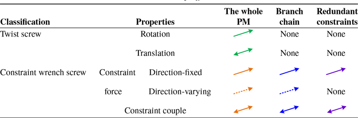
. For the sake of the graphical representation, some symbols are utilized to denote different screws, as shown in Table I.
Notation of different screws.

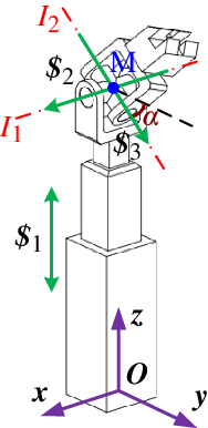
PU virtual chain.

2.2. Constraint analysis of PU virtual-chain and constraint characteristics of PU-equivalent PMs
Based on virtual-chain approach [Reference Kong and Gosselin8], the kinematic characteristics of PU-equivalent PMs can be expressed by a PU virtual-chain, as shown in Fig. 1, where the position of I 1-axis changes with the translation of the prismatic joint and I 2-axis rotates around I 1-axis. These two rotational axes are coplanar and intersect at a common point M under any configuration. For convenience, the coordinate of intersection point M is defined as (0, 0, z m ), the rotational angle around I 1-axis is set as α, so the twist system of the PU virtual-chain can be written as
 \begin{align}\left\{ \begin{array}{l@{\quad}l@{\quad}l@{\quad}l@{\quad}l@{\quad}l@{\quad}l}{{\rm{\$ }}_1} = (0 & 0 & 0 & ; & 0 & 0 & 1)\\[4pt]{{\rm{\$ }}_2} = (1 & 0 & 0 & ; & 0 & {{z_m}} & 0)\\[4pt]{{\rm{\$ }}_3} = (0 & {{\rm c}\alpha}& {{\rm s}\alpha} & ; & - {z_m}{{\rm c}\alpha} & 0 & 0)\end{array} \right.\end{align}
where c and s denote the sine and cosine functions, respectively. Using reciprocal screw theory [Reference Huang, Zhao and Zhao33], the wrench system of PU virtual-chain under general configuration with respect to the coordinate system O-xyz can be figured out as
 \begin{align}\left\{\begin{array}{l@{\quad}l@{\quad}l@{\quad}l@{\quad}l@{\quad}l@{\quad}l}{\rm{\$ }}_1^{{r}} = (1 & 0 & 0 & ; & 0 & {{z_m}} & 0)\\[4pt]{\rm{\$ }}_2^{{r}} = (0 & 1 & 0 & ; & { - {z_m}} & 0 & 0)\\[4pt]{\rm{\$ }}_3^{{r}} = (0 & 0 & 0 & ; & 0& {{{\rm s}} \alpha } & { - {{\rm c}} \alpha } )\end{array} \right.\end{align}
where
 $\$_{1}^{r}$
and
 $\$_{2}^{r}$
denote constraint forces passing point M and parallel to x- and y-axes, respectively,
 $\$_{3}^{r}$
denotes a constraint couple perpendicular to I
1- and I
2-axis and related to the rotational angle α of I
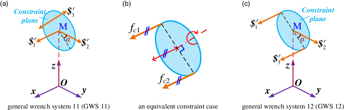
2-axis. General wrench system shown in Fig. 2(a) demonstrates the basic constraint situation of PU-equivalent PMs without redundant constraints, namely, their constraint characteristics under general configuration. For convenience, this general wrench system is abbreviated as GWS 11. Herein, the constraint plane is defined, which is perpendicular to the constraint couple and contains the intersection point of the constraint forces, including basic information of constraints in GWS 11. Obviously, the constraint plane is coincident with the plane determined by I
1- and I
2-axis, and it will be further utilized to illustrate the cause of one parasitic motion. According to screw theory [Reference Huang, Zhao and Zhao33], two parallel constraint forces constrain a translation in the same direction of them and a rotation whose axis is perpendicular to the plane determined by them, as shown in Fig. 2(b), which equals
 $\$_{1}^{r}$
and
 $\$_{3}^{r}$
of GWS 11. Thus, an equivalent wrench system of GWS 11 can be obtained as shown in Fig. 2(c), which is denoted byGWS 12, and the constraint plane is now coincident with the plane determined by these two parallel constraint forces.
General wrench system of PU-equivalent PMs. (a) General wrench system 11 (GWS 11),(b) an equivalent constraint case, (c) general wrench system 12 (GWS 12).

2.3. Cause of parasitic motion and constraint characteristics of P*U*-equivalent PMs with one parasitic motion
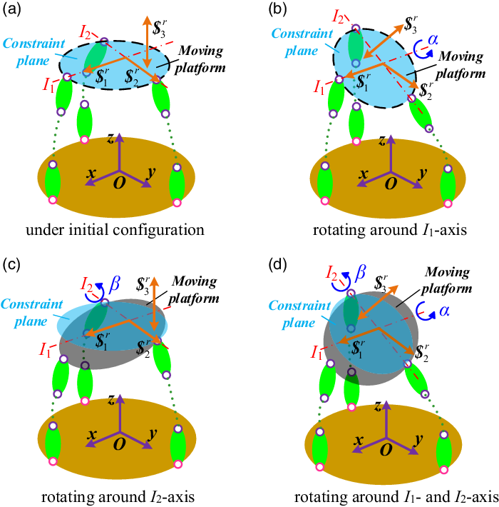
To illustrate the occurrence of the parasitic motion in a clearer manner, the difference between moving platform and constraint plane is further analyzed by taking PU-equivalent PMs with GWS 11 as example. As shown in Fig. 3(a) and (b), the constraint plane and moving platform are coincident with each other when PU-equivalent PMs are under initial configuration or rotating around I 1-axis. However, they will become different planes after PU-equivalent PMs rotating around I 2-axis or I 1- and I 2-axis, as shown in Fig. 3(c) and (d).
Difference between the constraint plane and moving platform. (a) Under initial configuration, (b) rotating around I 1-axis, (c) rotating around I 2-axis, (d) rotating around I 1- and I 2-axis.

The only intersection line of the constraint plane and moving platform is the I
2-axis, that is to say, if the constraint force
 $\$_{2}^{r}$
does not intersect with the moving platform by I
2-axis, it will change its position with respect to the constraint plane when the PU-equivalent PMs rotate around I
1- and I
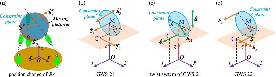
2-axis, as shown in Fig. 4(a). Under this situation, one parasitic motion occurs along with the rotation of the moving platform, and the process of proof is as following.
Cause of one parasitic motion and corresponding general wrench systems. (a) Position change of
 $\$_2^{r}$
, (b) GWS 21, (c) twist system of GWS 21, (d) GWS 22.

Wrench system of Fig. 4(a) is denoted by general wrench system 21 (GWS 21) in Fig. 4(b), where point C is the intersection point of
 $\$_{2}^{r}$
with the O-xz plane, and its coordinate is set to be (x
c
, 0, z
c
). Based on screw theory, GWS 21 can be written as
 \begin{align}\left\{\begin{array}{l@{\quad}l@{\quad}l@{\quad}l@{\quad}c@{\quad}c@{\quad}c}\$ _1^r = ( 1 & 0 & 0 & ; & 0 & {{z_m}} & 0)\\[4pt]\$ _2^r = ( 0 & 1 & 0 & ; & { - {z_c}} & 0 & {{x_c}})\\[4pt]\$ _3^r = ( 0 & 0 & 0 & ; & 0 & {\sin \alpha } & { - \cos \alpha })\end{array} \right.\end{align}
The twist system of GWS 21 can be figured out as
 \begin{align}\left\{\begin{array}{l@{\quad}l@{\quad}l@{\quad}l@{\quad}c@{\quad}c@{\quad}c}{\$ _1} = ( 0 & 0 & 0 & ; & 0 & 0 & 1 )\\[4pt]{\$ _2} = ( 1 & 0 & 0 & ; & 0 & {{z_c}} & 0 )\\[4pt]{\$ _3} = ( 0 & {{{\rm c}} \alpha } & {{{\rm s}} \alpha } & ; & { - {z_m}{{\rm c}} \alpha } & { - {x_c}{{\rm s}} \alpha } & 0 )\end{array} \right.\end{align}
where
 $\$_1$
represents a translation along the z-axis,
 $\$_2$
denotes a rotation that is parallel to the x-axis and goes through point C,
 $\$_3$
is a twist that can be divided into a translation
 $\$_{31}$
and a rotation
 $\$_{32}$
by rule of algebraic sum of two screws [Reference Huang, Zhao and Zhao33], where
 \begin{align}\left\{ \begin{array}{l}{\$ _{31}} = \left( 0\quad0\quad0\quad;\quad0\quad{ - {x_c}{{\rm s}} \alpha }\quad0 \right)\\[5pt]{\$ _{32}} = \left( 0\quad{{\mathop{\rm c}} \alpha }\quad{{\mathop{\rm s}\nolimits} \alpha }\quad;\quad{ - {z_m}{\mathop{\rm c}\nolimits} \alpha }\quad0\quad0\right)\end{array} \right.\end{align}
As shown in Fig. 4(c),
 $\$_{31}$
represents a motion of one constrained DOF, namely, a translation parallel to the y-axis, while
 $\$_{32}$
represents a rotation whose axis goes through the center of the constraint plane, and the axial direction is related to the rotational angle of the constraint plane. Additionally, the rotational axis of
 $\$_2$
is instantaneous for the coordinate of intersection point C will change with the rotation of moving platform. Similarly, we could obtain an equivalent wrench system of GWS 21, which is denoted by GWS 22, as shown in Fig. 4(d).
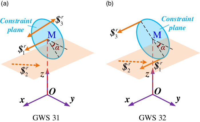
According to screw theory [Reference Huang, Zhao and Zhao33], if the real unit of a constraint force contains the components on z-axis, the translation along z-axis will be prohibited. Thus, all constraint forces of P*U*-equivalent PMs with one parasitic motion should be parallel to the O-xy plane. However, if
 $\$_2^{r}$
of GWS 21 and 22 could change its position while remains to be parallel to the O-xy plane as shown in Fig. 5(a) and (b), one parasitic motion will occur as well, which can be proved as above and the generated parasitic motion will be different in kinematics. These two wrench systems are denoted by GWS 31 andGWS 32, respectively.
Other general wrench systems of P*U*-equivalent PMs with one parasitic motion.(a) GWS 31, (b) GWS 32.

2.4. Constraint characteristics of P*U*-equivalent PMs with three parasitic motions
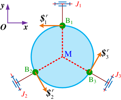
Constraint characteristics of P*U*-equivalent with three parasitic motions are more complicated for the complex spatial distributions of the two rotational axes after continuous rotation of moving platform. Thus, the research on general wrench systems of P*U*-equivalent PMs with three parasitic motions will be conducted based on the constraint analysis of existing PMs. According to the conclusion proposed by Li [Reference Li, Chen, Chen, Wu and Hu24], when three LPs (limb planes) of 3-PRS PM are arranged symmetrically and intersect at aline with noncollinear spherical centers, parasitic motions appear in three constrained DOFs. For more distinct expression of the properties of constraint forces, the 3-PRS PM is projected to the O-xy plane, as shown in Fig. 6. It is noticeable that three constraint forces are restricted to be parallel to J 1-, J 2- and J 3-axis and go through the spherical centers B i (i =1, 2, 3) for their geometric constraints.
Projection view on O-xy plane of constraint forces for 3-PRS PM with three parasitic motions.

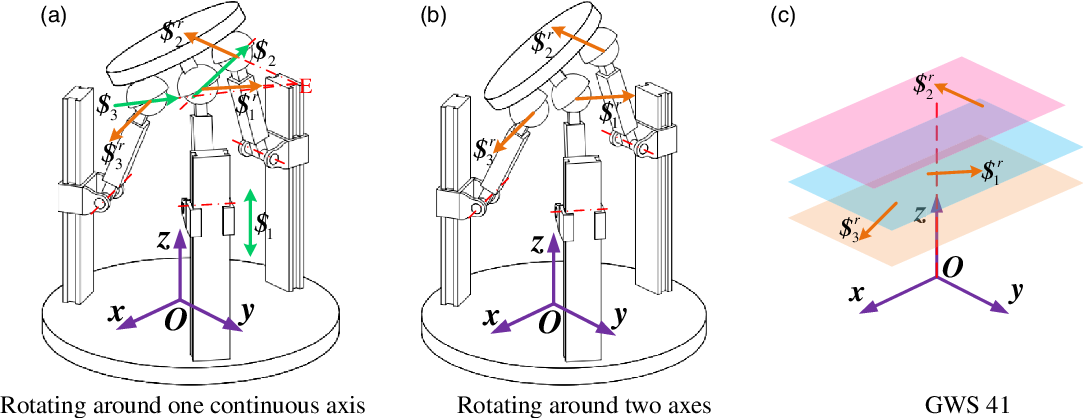
The connecting line of any two spherical centers of 3-PRS PM can be considered as a continuous rotational axis of the moving platform [Reference Huang, Tao and Fang21]. If the moving platform rotates around one of these three continuous rotational axes, the constraint wrench system and the twist system of 3-PRS PM are shown in Fig. 7(a), where point E is the intersection point of the constraint force
 $\$_1^{r}$
and
 $\$_2^{r}$
. Herein,
 $\$_1$
denotes a translation parallel to z-axis,
 $\$_2$
represents a rotation whose axis intersect the constraint force
 $\$_1^{r}$
and
 $\$_2^{r}$
and
 $\$_3$
stands for an instantaneous rotation whose axis intersect point E and the constraint force
 $\$_3^{r}$
. Obviously, there is no parasitic motion at this time.
Constraint analysis and general wrench system of P*U*-equivalent PMs with three parasitic motions. (a) Rotating around one continuous axis, (b) rotating around two axes, (c) GWS 41.

However, when the moving platform rotates around two different axes, namely, the displacements of three actuated prismatic joints are different from each other, three constraint forces will not be on a common plane, as shown in Fig. 7(b), and three parasitic motions appear under this situation. Thus, we could draw the conclusion that the wrench system of P*U*-equivalent PMs with three parasitic motions consists of three linearly independent constraint forces. Furthermore, three of them are coplanar on the moving platform under initial configuration, two of them are coplanar when rotating around one continuous axis, and they are not on a common plane and do not intersect the same line under general configuration, as shown in Fig. 7(c). Such a wrench system is denoted by GWS 41.
3. Synthesis of branch chains
3.1. Classification of branch chains and its rules of synthesis
Based on screw theory [Reference Huang, Zhao and Zhao33], the twist system of PM is an intersection set of twist system of each branch, while the wrench system of PM is a union set of wrench system of each branch. Thus, each branch chain of PU- or P*U*-equivalent PMs should have at least two rotational and one translational three DOFs and could provide at most two constraint forces and one constraint couple. Therefore, we could classify branches into six categories: 1T2R, 1T3R, 2T2R, 2T3R, 3T2R and 3T3R, which could generate two constraint forces and one constraint couple, two constraint forces, one constraint force and one constraint couple, one constraint force, one constraint couple and no constraint, respectively.
Analysis above has demonstrated all feasible basic wrench systems of PU- and P*U*-equivalent PMs, revealing their constraint characteristics, namely, distributions and properties of constraints. The reciprocal product of constraint wrench screw and twist screw can be further written as
 \begin{align}{{{\$}}_i} \circ {\$}_j^r = {l_i}{p_j} + {m_i}{q_j} + {n_i}{r_j} + {p_i}{l_j} + {q_i}{m_j} + {r_i}{n_j} {\rm{ }} = {\omega _i}{f_j}\left[ {({h_i} + {h_j})\cos {\alpha _{ij}} - {a_{ij}}\sin {\alpha _{ij}}} \right] \end{align}
where α ij denotes the torsion angle of axes of two screws, and a ij denotes the mutual moment of axes of two screws. According to Eq. (8), two line vectors (h = 0) are reciprocal only when they are parallel (sinα ij = 0) or intersecting (a ij = 0); two couples are certainly reciprocal; and a line vector and a couple are reciprocal only when they are perpendicular (cosα ij = π/2). Based on this and constraint characteristics, rules of synthesis of structures of different kinds of branch chains are determined as following:
-
(a) If a branch chain generates a constraint force, all rotational axes of revolute joints in this branch chain should be parallel to or intersect with the constraint force, and axes of prismatic joints should be perpendicular to the constraint force. Additionally, the intersection point of rotational axes and constraint force should locate at the end of the branch chain;
-
(b) If a branch chain generates a constraint couple, all rotational axes of revolute joints in this branch chain should be perpendicular to the constraint couple, and there is no limit for the axes of prismatic joints;
-
(c) If a branch chain generates constraint force and couple at the same time, it should meet the above two conditions at the same time.
3.2. Feasible structures of different branch chains
3.2.1. Structures of 1T2R and 1T3R branch chain
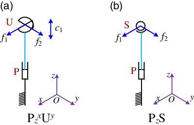
Both 1T2R and 1T3R branch chain could generate two linearly independent constraint forces, and they should locate on the moving platform under initial configuration. According to rule (a), structure of 1T2R branch chain could only be
 $\mathrm{P}_z^x \mathrm{U}^{y}$
, and structure of 1T3R branch chain could only be P
z
S, as shown in Fig. 8, where f
i
denotes corresponding constraint forces and c
i
denotes corresponding constraint couple. These two structures also restrict the rotational center of 1T2R PMs contained them, namely, center of universal or spherical joint. Thus, P*U*-equivalent PMs without determined rotational center could not contain 1T2R or 1T3R branch chain.
Structures of 1T2R and 1T3R branch chain. (a)
 ${P}_z^x {U}^{y}$
, (b) P
z
S.

3.2.2. Structures of 2T2R branch chain
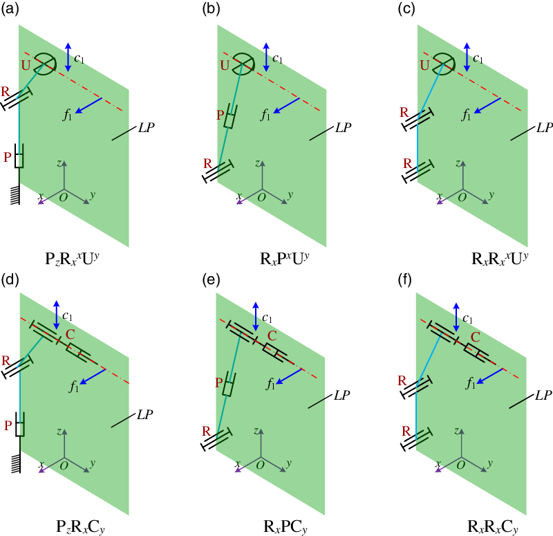
2T2R branch chain could generate a constraint force and a constraint couple and contain two linearly independent revolute joints. According to rule (a), the plane determined by two translational DOFs must be perpendicular to the constraint force, and revolute joint with axis intersecting at the constraint force must locate at the end of the branch chain. According to rule (b), the axial direction of the last revolute joints could and only could change once. Hence, the limb plane (LP) of 2T2R branch chain is fixed and perpendicular to O-xy plane, and there only exists one revolute joint which is not parallel to the constraint force. As shown in Fig. 9, feasible structures of 2T2R branch chain for PU- and P*U*-equivalent PMs are P z R x x U y , R x P x U y , R x R x x U y , P z R x C y , R x PC y and R x R x C y , where cylindrical joint can be considered to be the combination of a prismatic joint and a revolute joint with coincident axis. Note that structures with other prismatic joints are out of consideration herein.
Feasible structures of 2T2R branch chain. (a) P
z
 $R_x^x$
U
y
, (b) R
x
P
x
U
y
, (c) R
x
 $R_x^x$
U
y
, (d) P
z
R
x
C
y
, (e) R
x
PC
y
, (f) R
x
R
x
C
y
.

3.2.3. Structures of 2T3R branch chain
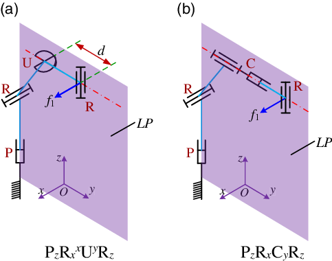
2T3R branch chain could only generate a constraint force, and its feasible structures can be obtained by adding another linearly independent revolute joint to 2R2T branch chains shown in Fig. 9. Based on Section 2, they can be divided into two categories: one generating direction-fixed constraint force, the other generating direction-varying constraint force, and both of them should be parallel to the O-xy plane. For the former category, the linearly independent revolute joint should be added at the end of feasible 2T2R branch chains, and thus we can obtain feasible structures of 2T3R branch chain: P
z
 $\mathrm{R}_x^x\mathrm{U}^y\mathrm{R}_z$
, R
x
P
x
U
y
R
z
, R
x
 $\mathrm{R}_x^x\,\mathrm{U}^y\,\mathrm{R}_z$
, P
z
R
x
C
y
R
z
, R
x
PC
y
R
z
, R
x
R
x
C
y
R
z
. Figure 10 shows P
z
 $\mathrm{R}_x^x\mathrm{U}^y\mathrm{R}_z$
and P
z
R
x
C
y
R
z
branch chain as examples, and the generating constraint force must go through the intersection point of last two rotational axes. Furthermore, P
z
 $\mathrm{R}_x^x\mathrm{U}^y\mathrm{R}_z$
, R
x
P
x
U
y
R
z
and R
x
 $\mathrm{R}_x^x\mathrm{U}^y\mathrm{R}_z$
branch chain will translate into P
z
R
x
S, R
z
PS and R
x
R
x
S branch chain when d (distance of center of universal joint and revolute joint, as shown in Fig.10(a)) equals 0.
Two feasible structures of 2T3R branch chain. (a) P
z
 ${R}_x^x{U}^y{R}_z$
, (b) P
z
R
x
C
y
R
z
.

Obviously, if the above six 2T3R branch chains are utilized to provide
 $\$_2^{r}$
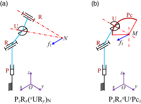
of GWS 11 and 12, centers of last revolute joints of branch chains generating two basic constraint forces must be collinear, and three branch chains should satisfy “T” shape layout, which may lower performance of corresponding PMs [Reference Sun and Huo25]. Hence, it is necessary to develop 2T3R branch chain whose constraint force are with distal acting point. Meanwhile, the acting point is determined by the intersection point of other two linearly independent rotational axes, and thus expected branch chain: P
z
R
x
(
x
UR
y
)N, R
x
P(
x
UR
y
)N, R
x
R
x
(
x
UR
y
)N can be obtained by keeping these two revolute joints are angled in structure, as shown in Fig. 11(a). Additionally, the last revolute joint shown in Fig. 10(a) can be replaced by an arc slider whose center line is collinear with corresponding rotational axis, as shown in Fig. 11(b), and we can obtain P
z
R
x
x
U
y
Pc
z
, R
x
P
x
U
y
Pc
z
and R
x
R
x
x
U
y
Pc
z
branch chain.
Two feasible structures of 2T3R branch chain with distal constraint force acting point.(a) P
z
R
x
(
x
UR
y
)N, (b) P
z
 $R_x^x$
U
y
Pc
z
.

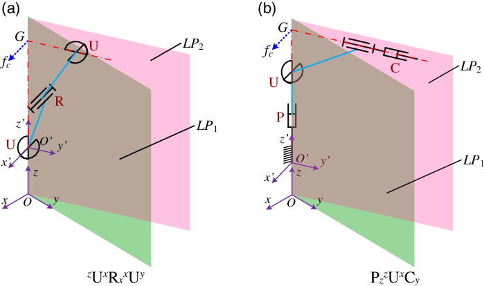
For 2T3R branch chain generating direction-varying constraint force, the limb plane (LP) could rotate around a fixed axis and should be perpendicular to O-xy plane. Thus, axis of the linearly independent revolute joint must be parallel to z-axis and added at the beginning of 2R2T branch chain shown in Fig. 9, and we could obtain expected branch chain: P z z U xx U y , z U x P x U y , z U x R x x U y , P z z U x C y , z U x PC y and z U x R x C y . Figure 12 shows z U x R x x U y and P z z U x C y branch chain as examples. According to rule (a), the generating constraint force is perpendicular to LP that could rotate around the first rotational axis and goes through the intersection point of the additional rotational axis and the last rotational axis, namely, point G in Fig. 12.
Two feasible structures of 2T3R branch chain with direction-varying constraint force.(a)
z
U
x
 $R_x^x$
U
y
, (b)
 $P_z^z$
U
x
C
y
.

3.2.4. Structures of 3T2R and 3T3R branch chain
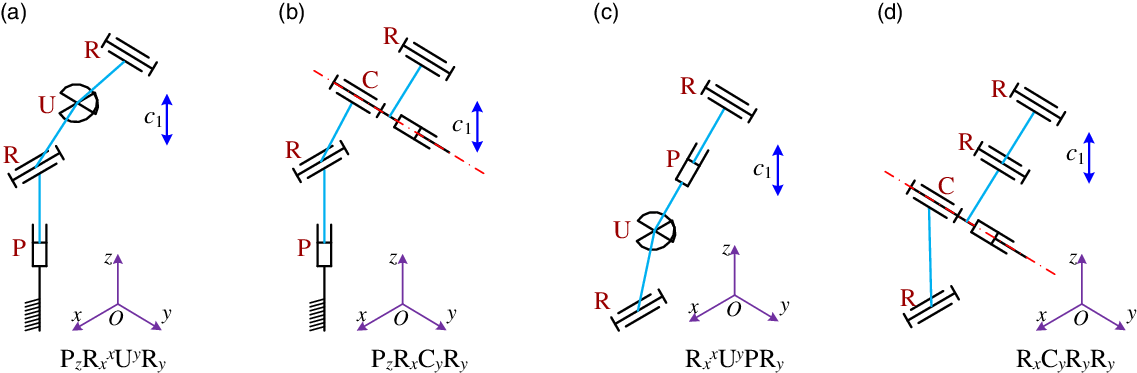
3T2R branch chain could only generate a constraint couple, and the number of linearly independent revolute joints is two. To satisfy rule (b), we could add another parallel revolute joint at the end of 2T2R branch chain shown in Fig. 9 and obtain expected 3T2R branch chain: P
z
 $\mathrm{R}_x^x$
U
y
R
y
, R
x
P
x
U
y
R
y
, R
x
 $\mathrm{R}_x^x$
U
y
R
y
, P
z
R
x
C
y
R
y
, R
x
PC
y
R
y
and R
x
R
x
C
y
R
y
, as shown in Fig. 13(a) and (b). Furthermore, by meeting the condition that the direction of the last rotational axis could only change once, other feasible 3T2R branch chain can be obtained:
 $\mathrm{R}_x^x$
U
y
PR
y
,
 $\mathrm{R}_x^x$
U
y
R
y
R
y
, R
x
R
x
PR
y
R
y
, R
x
C
y
R
y
R
y
, C
x
 $\mathrm{R}_x^x$
U
y
and C
x
x
U
y
R
y
, as shown in Fig. 13(c) and (d).
Four feasible structures of 3T2R branch chain. (a) P
z
 $R_x^x$
U
y
R
y
, (b) P
z
R
x
C
y
R
y
, (c)
 $R_x^x$
U
y
PR
y
, (d) R
x
C
y
R
y
R
y
.

3T3R branch chain generates no constraints, we will not go any further herein since its feasible structures such as UPS, SPS, PUS and PUS are well known to us.
3.2.5. Summary
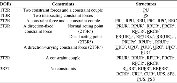
According to aforementioned analysis, detailed structures of branch chains have been demonstrated under their local coordinate systems. As shown in Table II, since some 2T3R branch chain and 3T2R branch chain are composed of the same kinematic joints and the difference is the layout of axes, so 2T3R branch chains are denoted by superscript “f” and 3T2R branch chains are denoted by superscript “c”. 2T3R branch chain can be further divided into three categories, and they are denoted by 2T3R n , 2T3R d and 2T3R v branch chain, respectively. Note that the underlined kinematic joints are the actuated joints of each branch chain.
Summary of feasible branch chains.

4. Type Synthesis of PU- and P*U*-Equivalent PMs
Based on the aforementioned general wrench systems and feasible branch chains, detailed process of type synthesis of PU- and P*U*-equivalent PMs is as following:
-
STEP 1. Select corresponding general wrench systems based on the type of 1T2R PMs required to be synthesized (PU or P*U*);
-
STEP 2. According to the properties of constraints in the selected general wrench system, along with constraints generated by six categories of branch chains, the numbers and properties of redundant constraints are determined and all situations of constraints distributions of the selected general wrench system are obtained;
-
STEP 3. According to all the constraints distributions of the selected general wrench system and constraints of branch chains, all combinations of constraints in three branch chains of each constraints distribution are determined;
-
STEP 4. Select corresponding kinds of branch chains and determine assembly conditions of each case; obtain corresponding 1T2R PMs by configuring the selected branch chains on the basis of assembly conditions;
-
STEP 5. Choose other general wrench systems and repeat STEP 2–4 until all kinds of PU- and P*U*-equivalent PMs have been synthesized.
 $\prod_i(i = 1, 2, 3)$
represents three different branch chains in assembly conditions for convenience. Several geometric conditions are defined as following for better illustration of different assembly conditions: ‘
 $\odot$
’ denotes no extra limits for layouts of branch chains; ‘
 $//$
’ denotes the first revolute axis of two branch chains are parallel; ‘
 $\div$
’ denotes two LPs are coplanar under any configuration; ‘⊥’ denotes two LPs are perpendicular under initial configuration; ‘≒’ denotes the line between two centers of terminal kinematic joints in two different branch chains are parallel to the moving platform under any configuration; ‘≡’ denotes the last revolute axes of two limbs are collinear; ‘∧’ denotes the distal acting point of 2T3R
d
branch chain intersects with the rotational center of the moving platform; ‘
 $|\!\!\!-$
’ denotes the midpoint of connecting line of the terminal kinematic joint of two identical branched chains; ‘∩’ denotes two branch chains must satisfy geometric conditions at the same time.
4.1. Type synthesis of PU-equivalent PMs
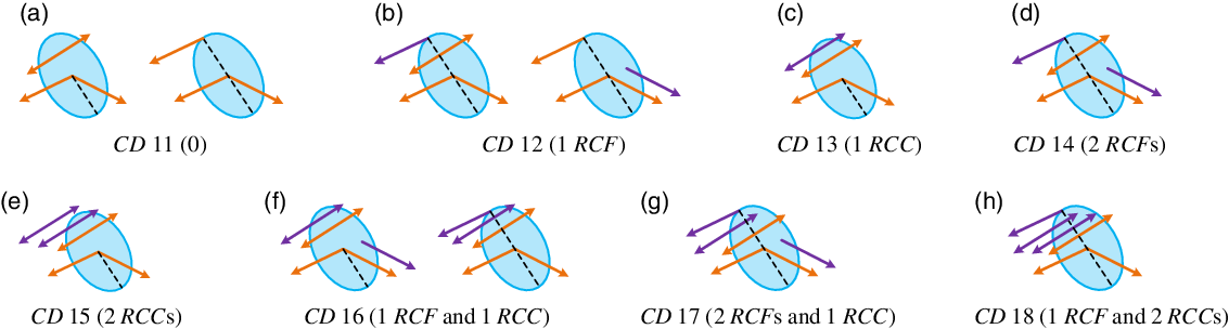
The key of type synthesis is to obtain all kinds of constraints distributions according to different general wrench systems, and then determine assembly conditions based on chosen branch chains. Since PU and PS branch chain generates two basic linearly independent constraint forces and restrict the rotational center of the PMs, we will discuss constraint distributions of PU-equivalent PMs with or without PU/PS branch chain separately. Based on numbers and properties of redundant constraints, all constraints distributions (abbreviated as CD) of PU-equivalent PMs with PU/PS branch chain are obtained, as shown in Fig. 14. For simplification, redundant constraint force is denoted by RCF, and redundant constraint couple is denoted by RCC.
All constraint distributions of PU-equivalent PMs with PU/PS branch chain. (a) CD 11 (0), (b) CD 12 (1 RCF), (c) CD 13 (1 RCC), (d) CD 14 (2 RCFs), (e) CD 15 (2 RCCs), (f) CD 16 (1 RCF and 1 RCC), (g) CD 17 (2 RCFs and 1 RCC), (h) CD 18 (1 RCF and 2 RCCs).

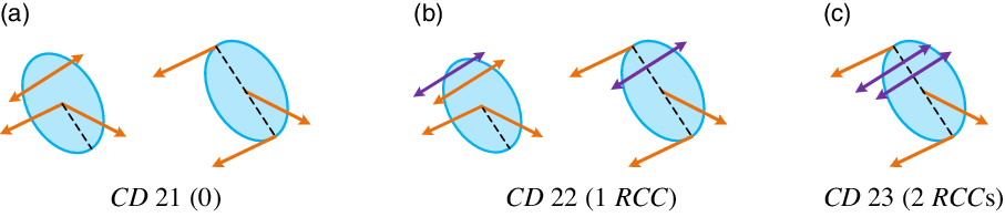
Similarly, all constraints distributions of PU-equivalent PMs without PU or PS branch chain are obtained in the same way, as shown in Fig. 15. Although some constraint distributions are the same as above, they are grouped into different categories for their different compositions of branch chains.
All constraint distributions of PU-equivalent PMs without PU/PS branch chain. (a) CD 21 (0), (b) CD 22 (1 RCC), (c) CD 23 (2 RCCs).

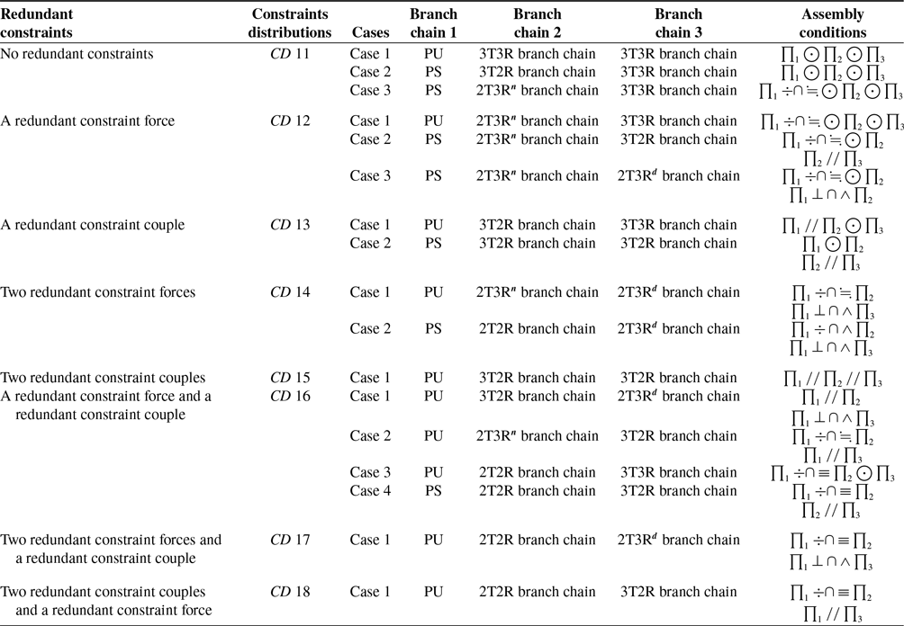
Type synthesis of PU-equivalent PMs with PU/PS branch chain.

4.1.1. Type synthesis of PU-equivalent PMs with PU/PS branch chain
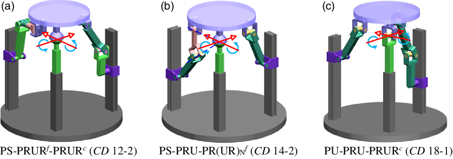
Based on the constraint distributions shown in Fig. 14, all cases of different combinations of branch chains and corresponding assembly conditions are listed in Table III, and type synthesis of PU-equivalent PMs with PU/PS branch chain is finished by mechanism configuration. Obviously, existing 1T2R PMs can be systematically categorized and obtained by this method, e.g., PU-RPUR-UPS [Reference Song, Han and Wang27] belongs to CD 13-1, PU-RPU-UPS [Reference Xu, Zhang, Yao and Zhao28] and PU-PRC-UPS [Reference Fan, Liu and Zhang26] belong to CD 16-3, PS-RPUR-UPS [Reference Song, Han and Wang27] belongs to CD 11-2, PS-RPS-UPS [Reference Song, Han and Wang27] belongs to CD 11-3 and PU-RPS-UPS [Reference Song, Han and Wang27] belongs to CD 12-1. Many novel 1T2R PMs can also be obtained using this type synthesis method, e.g., PS-PRUR f -PRUR c ,PS-PRU-PR(UR)N f and PU-PRU-PRUR c , as shown in Fig. 16, where the red arrows indicate the two rotational axes of novel PMs. Other novel PMs be obtained in the same way by replacing branch chains of a sort, and there is no more description for space saving.
Three novel PMs of PU-equivalent PMs with PU/PS branch chain. (a) PS-PRUR f -PRUR c (CD 12–2) (b) PS-PRU-PR(UR)N f (CD 14–2) (c) PU-PRU-PRUR c (CD 18–1).

4.1.2. Type synthesis of PU-equivalent PMs without PU/PS branch chain
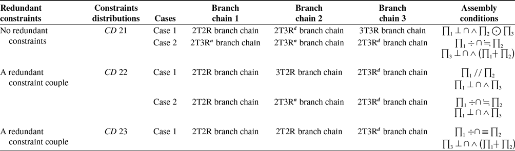
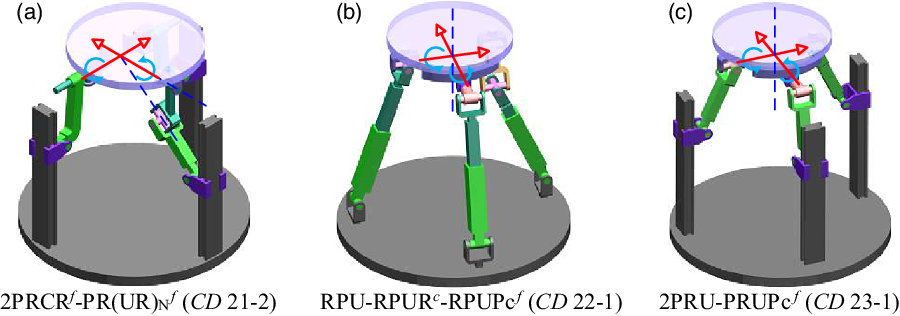
Table IV shows all combinations of branch chains and corresponding assembly conditions of PU-equivalent PMs without PU/PS branch chain. For existing 1T2R PMs, RPUR-RPU-UPS [Reference Song, Han and Wang27] belongs to CD 21-1, 2RPU-RPUR [Reference Song, Han and Wang27] belongs to CD 23-1. Figure 17 gives three novel PMs as examples, and they are 2PRCR f -PR(UR)N f , RPU-RPUR c -RPUPc f and 2PRU-PRUPc f . Note that the distal acting point of 2T3R d branch chain is the rotational center of PMs.
Type synthesis of PU-equivalent PMs without PU/PS branch chain.

Three novel PMs of PU-equivalent PMs without PU/PS branch chain. (a) 2PRCR f -PR(UR)N f (CD 21–2), (b) RPU-RPUR c -RPUPc f (CD 22–1), (c) 2PRU-PRUPc f (CD 23–1).

4.2. Type synthesis of
 $P^{\ast}U^{\ast}$
-equivalent PMs with one parasitic motion

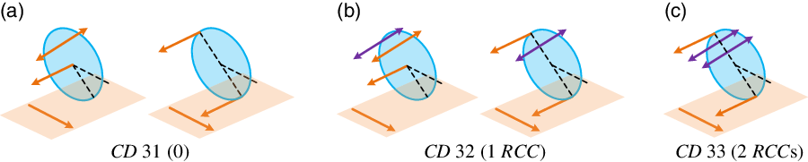
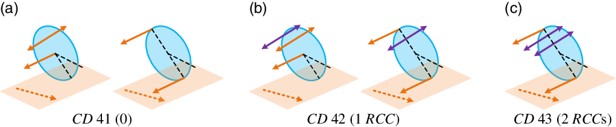
The difference between GWS 21, 22 and GWS 31, 32 is the properties of the time-varying constraint force, and thus both of them should contain at least one 2T3R branch chain to provide required constraint force, which means that their constraint distributions could have two redundant constraints at most. As shown in Figs. 18 and 19, their constraint distributions are quite similar.
All constraint distributions of P*U*-equivalent PMs of GWS 21 and 22. (a) CD 31 (0),(b) CD 32 (1 RCC), (c) CD 33 (2 RCCs).

All constraint distributions of P*U*-equivalent PMs of GWS 31 and 32. (a) CD 41 (0),(b) CD 42 (1 RCC), (c) CD 43 (2 RCCs).

4.2.1. Type synthesis of
$P^{\ast}U^{\ast}$
-equivalent PMs of GWS 21 and 22

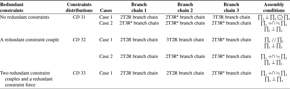
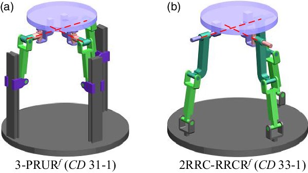
Table V shows all combinations of branch chains and corresponding assembly conditions of P*U*-equivalent PMs of GWS 21 and 22, and the existing 2PRU-PRS [Reference Xie, Liu and Li30, Reference Herrero, Pinto, Altuzarra and Mikel31] PM belongs to CD 33–1. Two novel synthesized P*U*-equivalent PMs, namely, 3-PRUR f and 2RRC-RRCR f are given as examples, as shown in Fig. 20.
Type synthesis of P*U*-equivalent PMs of GWS 21 and 22.

Two novel PMs of P*U*-equivalent PMs of GWS 21 and GWS 22. (a) 3-PRUR f (CD 31–1), (b) 2RRC-RRCR f (CD 33–1).

4.2.2. Type synthesis of
$P^{\ast}U^{\ast}$
-equivalent PMs of GWS 31 and 32

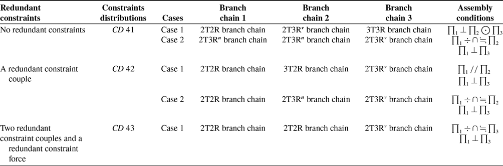
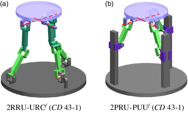
Table VI shows all combinations of branch chains and corresponding assembly conditions of P*U*-equivalent PMs of GWS 31 and 32, and this type of P*U*-equivalent PMs have not been researched before. Two novel synthesized P*U*-equivalent PMs, namely, 2RRU-URC f and 2PRU-PUU f , are shown in Fig. 21 as examples.
Type synthesis of P*U*-equivalent PMs of GWS 31 and 32.

Two novel PMs of P*U*-equivalent PMs of GWS 31 and GWS 32. (a) 2RRU-URC f (CD 43–1), (b) 2PRU-PUU f (CD 43–1).

4.3. Type synthesis of
$P^{\ast}U^{\ast}$
-equivalent PMs with three parasitic motions

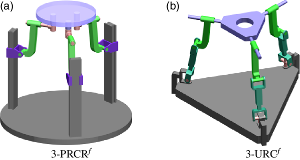
According to Subsection 2.4, GWS 41 consists of three linearly independent constraint forces, which should be coplanar on the moving platform under initial configuration. Thus, there exists no redundant constraints, and if three 3T2R n or 3T2R v branch chains are layout like the typical 3-PRS PM, the change of constraint forces will conform to the constraint characteristics of P*U*-equivalent PMs with three parasitic motions. Two novel PMs, namely, 3-PRCR f and 3-URC f , are shown in Fig. 22 as examples.
Two novel PMs of P*U*-equivalent PMs of GWS 41. (a) 3-PRCR f , (b) 3-URC f .

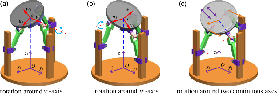
Mobility of 2PRU-PRUPc f PM. (a) Rotation around v 1-axis, (b) rotation around u 1-axis,(c) rotation around two continuous axes.

5. Analysis and Comparison
To verify the correctness of the type synthesis method, the synthesized 2PRU-PRUPc f and 2PRU-PUU f PM are taken as examples to perform mobility analysis. Additionally, parasitic motion of 2PRU-PUU f PM is analyzed and compared.
5.1. Mobility analysis of 2PRU-PRUPcf PM
Figure 23(a) and (b) show the moving platform configurations of the 2PRU-PRUPc f PM after undergoing finite rotations around the v 1-axis and the u 1-axis, respectively. Figure 23(c) shows the moving platform configuration and constraint situation after undergoing rotation around two continuous axes. The distal acting point of PRUPc branch chain, namely, rotational center of the 2PRU-PRUPc f PM, could only move along the z 1-axis, demonstrating the synthesized PM is exactly a PU-equivalent PM. In addition, the constraints distributions are truly the same as CD 23, which means that the mobility can be proved by reciprocal screw theory as well.
5.2. Mobility and parasitic motion analysis of 2PRU-PUUf PM
Similarly, Fig. 24(a) and (b) show the moving platform configurations of the 2PRU-PUU f PM after undergoing finite rotations around the v 2-axis and the u 2-axis, respectively. Obviously, the rotational center locates on the z 2-axis, and there is no parasitic motion under these two situations. However, one parasitic motion occurs when the moving platform rotates around two axes, and it is a parasitic translation d p along the x 2-axis, as shown in Fig. 24(c). Likewise, the constraints distributions of 2PRU-PUU f PM are the same as CD 33, and the mobility can be proved by reciprocal screw theory too.
Mobility of 2PRU-PUU f PM. (a) Rotation around v 1-axis, (b) rotation around u 1-axis,(c) rotation around two axes.

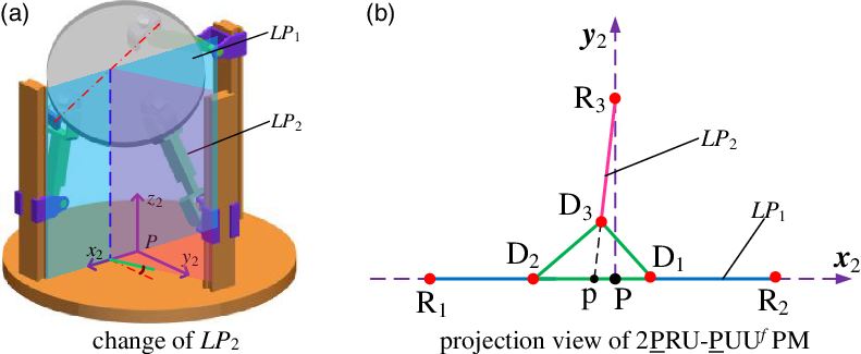
As shown in Fig. 25(a), limb plane of two PRU branch chain (LP 1) is fixed by the restriction of two revolute joints, while limb plane of the PUU f branch chain (LP 2) could rotate around the first rotational axis of the first universal joint that leads to the generation of parasitic motion along with the change of constraints. To solve the analytical solution of the parasitic motion, the 2PRU-PUU f PM is projected to the P-x 2 y 2 plane, as shown in Fig. 25(b), where R i (i =1, 2, 3) denotes centers of the first revolute or universal joints of three branch chains and D i (i =1, 2, 3) denotes centers of the second universal joints of three branch chains. Obviously, the projection line of LP 2, namely, R3D3 and center of the moving platform are collinear in the projection view, so we have
 \begin{align}{{\boldsymbol{k}}_{{R_3}{D_3}}} = {{\boldsymbol{k}}_{{D_3}p}}\end{align}
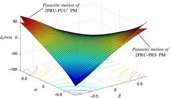
where k denote the slopes of line R3D3 and D3p, respectively. By substituting into the coordinates of the corresponding points analytical solution of the parasitic motion can be obtained, which have been drawn in Fig. 26.
Parasitic motion analysis of 2PRU-PUU f PM. (a) Change of LP 2, (b) projection view of 2PRU-PUU f PM.

Comparison of parasitic motion.

The existing 2PRU-PRS PM is a typical P*U*-equivalent PM with one parasitic motion, which has been further researched and applied [Reference Xie, Liu and Li30, Reference Herrero, Pinto, Altuzarra and Mikel31], including its parasitic motion. According to former analysis, the novel 2PRU-PUU f PM differs from the 2PRU-PRS PM in constraint characteristics, which reflects in their parasitic motion. In the case of the same parameters of these two PMs, it can be concluded that variation laws of their parasitic motion are similar, but the magnitude of parasitic motion of 2PRU-PUU f PM is larger than 2PRU-PRS PM, as shown in Fig. 26. However, manufacturing and assembly of 2PRU-PUU f PM are more convenient for the avoidance of the spherical joint.
6. Conclusions
This study proposes a simple, easily understandable, and effective method for type synthesis of PU- and P*U*-equivalent PMs based on their constraint characteristics. The conclusion is drawn as following:
-
(1) The general wrench systems of PU-equivalent PMs have been obtained according to virtual chain approach and screw theory. Generation of one parasitic motion has been analyzed and proved form prospects of constraints, and general wrench systems of P*U*-equivalent PMs with one parasitic motion have been derived. An existing 3-PRS PM is analyzed to obtain general wrench system of P*U*-equivalent with three parasitic motions. These general wrench systems demonstrating the detailed constraint characteristics of PU- and P*U*-equivalent PMs.
-
(2) Branch chains has been classified into six categories. Their feasible structures for PU- or P*U*-equivalent PMs have been determined by rules of branch chain synthesis and properties of constraints of different general wrench systems. 2T3R branch chain has been further analyzed and divided to provide constraint forces with different properties.
-
(3) Specific process of type synthesis has been given. Based on this, all the constraints distributions of general wrench systems, different types of three branch chains in the desired PMs, and corresponding assembly conditions have been figured out. By configuring mechanisms, this type synthesis method could not only obtain existing but also many novel PU- or P*U*-equivalent PMs. Mobility of two synthesized 2PRU-PRUPc and 2PRU-PUU PM has been verified, demonstrating the correctness of the proposed method.
Acknowledgements
This work reported here was supported by the 111 Project (Grant No. B18027) and the Six Talent Peaks Project in Jiangsu Province (Grant No. ZBZZ-012).
Competing Interests Declaration
The authors declare that this work has no conflict of interest.
Author Contributions
Yongjian JU was in charge of research and writing of this paper. Weisheng Xu and Gang Meng gave many constructive suggestions to improve this paper. Yi Cao pointed out the research direction and made detailed revisions tothis paper.