Nomenclature
- S U
-
the Uth centroid of hexagon panels
- F U1, F U2
-
rectangular panels in one of the kinematic chains
- R UV
-
revolute joints connected the rectangular panels
- L U
-
the Uth kinematic chain
- a, b, c, d, c p, g p, r s
-
structural dimension
-
 $\delta$
-
acute angle between the F and the S
-
$\beta$
-
acute angle between the G and the S
-
$\boldsymbol{$}$
UV
-
motion screw of the single closed-loop origami mechanism
-
$\boldsymbol{$}$
r
-
reciprocal screw
- n
-
number of rings of supporting mechanism
- S i,j
-
position vector of the centroid of floral discs S
- UV F i+1,j
-
position vector of the centroid of rod F in the unit D i+1,j
- U G i+1,j
-
position vector of the centroid of rod G in the unit D i+1,j
-
${}_{\rm{p}}^U{\boldsymbol{G}_{i,j}}$
-
position vector of the centroid of rod G in the unit D i,j
- U E i+1,j
-
position vector of the centroid of rod E in the unit D i+1,j
-
${}_{\rm{p}}^U{\boldsymbol{E}_{i,j}}$
-
position vector of the centroid of rod E in the unit D i,j
-
${}_{\rm{G}}^K{\boldsymbol{I}_{i + 1,j}},{}_{\rm{E}}^K{\boldsymbol{I}_{i + 1,j}}$
-
centroid position matrix of the G and E of the unit D i+1,j in the odd part
-
${}_{{\rm{Gp}}}^K{\boldsymbol{I}_{i + 1,j}},{}_{{\rm{Ep}}}^K{\boldsymbol{I}_{i + 1,j}}$
-
centroid position matrix of the G and E of the unit D i+1,j in the even part
-
${}_{\rm{G}}^K{\boldsymbol{I}_{i,j}},{}_{\rm{E}}^K{\boldsymbol{I}_{i,j}}$
-
centroid position matrix of the G and E of the unit D i,j in the odd part
-
${}_{{\rm{Gp}}}^K{\boldsymbol{I}_{i,j}},{}_{{\rm{Ep}}}^K{\boldsymbol{I}_{i,j}}$
-
centroid position matrix of the G and E of the unit D i,j in the even part
- K S i,j
-
centroid position matrix of the floral discs S of the unit D i,j in the even part
-
${}_{\rm{F}}^K{\boldsymbol{D}},{}_{\rm{G}}^K{\boldsymbol{D}},{}_{\rm{E}}^K{\boldsymbol{D}},{}_{\rm{S}}^K{\boldsymbol{D}}$
-
centroid position matrix of F, G, E and S in the Part K
- D K
-
centroid position matrix of all components in the Part K
-
${\boldsymbol{M}},\dot{\boldsymbol{M}},\ddot{\boldsymbol{M}}$
-
centroid position, velocity and acceleration matrix of all components
-
$\eta$
-
folding ratio
- E v
-
kinetic energy
- E p
-
potential energy
- Q
-
generalised force of the supporting mechanism
- N F1, N G1
-
quantity of F and G belonging to the inner rods
- N F2, N G2
-
quantity of F and G belonging to the outer rods
- TDU
-
tetrahedral deployable unit


1.0 Introduction
Deployable mechanism [Reference Deng1, Reference Tian, Gao, Jin, Liu, Ma, Fan and Guo2] is a type of transformable mechanism, which can vary their shape from a compact, packaged configuration to an operational, expanded configuration. In most cases, the packaged configuration is used for storage and transportation, while the expanded configuration is for work requirements. They are widely used in various engineering fields, such as architecture [Reference Xu3, Reference Tachi4], aerospace [Reference Tang, Liu, Xiao, Guo, Wang, Xie and Liu5–Reference Chang, Xu, Liang and Zhang9], medical [Reference Yang, Ma, Li, Chen and Wang10, Reference Edmondson, Bowen, Grames, Magleby, Howell and Bateman11], metamaterial [Reference Chen12, Reference Fang, Wu, Liu, Zhang and Xu13] and other fields. Deployable mechanisms are an extension of a basic deployable unit composed of rods and cables, and are usually overconstrained systems with simple configuration and good stiffness. Therefore, the design of the basic deployable unit is the foundation for constructing a large-scale deployable mechanism.
Origami is the art of folding essentially two-dimensional materials such as paper into three-dimensional objects, which is an efficient way to construct the basic deployable unit. It has recently gained popularity among scientists and engineers because the technique can be used to create shape-changing structures. The folded cardboard can form a certain number of creases and cardboard units, which can be equivalent to a revolute joint and component. Therefore, the same cardboard can form different mechanisms, called origami mechanisms, through different folding methods. The kinematic models of such mechanisms are usually established under the assumption that the thickness of the cardboard unit is zero and the stiffness is infinite. Various approaches were applied in determining the rigid foldability of specific crease: Watanabe proposed a graphical and numerical method [Reference Watanabe and Kawaguchi14]; Tachi derived the necessary and sufficient condition for the existence of finite rigid motion of general flat-foldable quadrilateral mesh origami [Reference Tachi15]; Cai established quaternion rotation sequence method and improved dual quaternion method to study the rigid foldability of the multi-vertex cylindrical-shaped origami patterns [Reference Cai, Zhang, Xu, Zhou and Feng16, Reference Cai, Liu, Ma, Feng and Zhou17]; Dai analysed the motion characteristics of rigid origami from the perspective of mechanism and proposed the concept of metamorphic mechanism and its topological structure [Reference Dai and Jones18, Reference Dai and Jones19]; Hull analysed the rigid foldability of single-vertex four-crease origami by spherical trigonometry [Reference Hull20]; Wang proposed the condition of rigid foldability of cylindrical origami by analysing motion coordination condition of spherical mechanism grid [Reference Wang, Chen, Wang-Iverson, Lang and Yim21]; Feng focuses on the widely used Waterbomb origami tubes, and based on the kinematics and compatibility of spherical linkages, the rigid folding behaviour of generalised Waterbomb tubes was systematically analysed with analytical kinematic equations to describe their rigid contract and twist motion [Reference Feng, Ma and Chen22].
In the engineering, if the panels folded according to the traditional origami method, it will cause physical interference. So it is a key problem for structural design and large-scale networking of deployable mechanisms with thick panels. Edmondson proposed an offset-panel method to solve the problem of physical interference in the process of deployment of thick panels model, the kinematics of the deployable mechanism with thick panels constructed by this method is completely equivalent to that of the corresponding rigid origami mechanism [Reference Edmondson, Lang and Magleby23]; Tachi proposed a method for geometrically constructing thick panel structures that follow the kinetic behaviour of rigid origami by using tapered or two-ply panels and hinges located at their edges [Reference Tachi24]; Wang proposed a kirigami-inspired approach, which selectively cuts some creases in origami patterns, is presented to create deployable surface structures with completely flat surfaces [Reference Wang, Zhang, Li and You25]; Chen [Reference Chen, Peng and You26] found the kinematically equivalent spatial linkages to the single-vertex origami patterns made from four, five and six creases, respectively, and then extended this to multiple vertex patterns by ensuring that the motion of the assembly of these linkages matches that of the zero-thickness pattern, and proposed the thick-panel models with four, five and six creases were equivalent to Bennett [Reference Bennett27, Reference Bennett28], Myard [Reference Myard29], and Bricard [Reference Baker30]; Zhang designed a new kind of regularly hexagonal origami pattern from the perspective of origami, and the DOF is reduced and controllability is improved by combing the theories of the truss method and thick-panel origami [Reference Zhang, Li, Cui, Chen, Ma and Chen31]. The aforementioned theoretical approaches examine and address the issue of physical interference during the deployment of thick panels. They establish multiple theoretical structure models and physical models of thick-panel deployable units, thereby providing a basis for the design of mechanisms for deploying thick panels.
In the realm of aerospace engineering, spacecrafts that are equipped with light-sensitive technology, such as star sensors, cameras and space telescopes, are significantly impacted by the light sources, particularly the sun. The sunshield outside the equipment can directly prevent the input of stray light, which has become an inevitable choice for many spacecrafts [Reference Liu, Cao and Lin32, Reference Wei, Lin, Lin and Tan33]. Recently, the structural styles of these deployable sunshields are mainly planar and cylindrical, while the deployment mechanisms include inflatable, mechanical and elastic deployments. Due to the space limitation of aerospace vehicles, the sunshield must be folded in the fairing during the launch phase, which requires the space occupied by the supporting mechanism of the sunshield to be as small as possible. Hence, it is imperative to integrate the design of the sunshield supporting mechanism with the deployable mechanism. The European Space Research and Technology Centre (ESTECT) had developed a petal-shaped sunshield for the Gaia space telescope, which was constructed by 12 rectangular petals and 12 triangular petals, and the sunshield membrane at the triangular petals is folded at the reserved crease and deployed by motor drive [Reference Pereira, Urgoiti and Pinto34, Reference Simpon, Broussely, Edwards, Robinso, Cozzani and Casarosa35]; Cash from the University of Colorado designed a planar deployable sunshield for the STARSHADE project, which was divided into a central area surrounded by deployable frame and a petal area, and the sunshield deployed by controlling the frame [Reference Cash36–Reference Sigel, Trease, Thomson, Webb, Willis and Lisman38]; Tong developed a sunshield constructed by six rectangular panels and six triangular panels for the MEAYIN mission, and the frame was drove by the hinge with spring [Reference Tong, Li, Cui, Huo and Luo39]; Yamane developed a V-shaped planar sunshield for the James Webb Space Telescope (JWST) launched in 2021, which was the largest planar sunshield in the world, and its supporting mechanism is mainly composed of front and rear deployable mechanisms and is deployed by rotation [Reference Greenhouse40–Reference Arenberg, Flynn, Cohen, Lynch and Cooper42].
The remainder of this paper is organised as follows. In Section 2, a single-DOF deployable units named tetrahedral deployable unit (TDU) derived from a new type of single closed-loop origami mechanism are proposed, and the TDU with high stability is selected to construct the supporting mechanism of the sunshield, a large-scale networking method has been proposed based on the TDU. In Section 3, the kinematic model and the folding ratio formula of the supporting mechanism is established, and a physical prototype is constructed. In Section 4, the dynamic model of the supporting mechanism is established, and the effects of different torsion spring parameters on the deployment motion of the supporting mechanism are analysed. Finally, conclusions are presented in Section 5, wherein the present work is summarised.
2.0 Design of supporting mechanism
2.1 Design of deployable unit
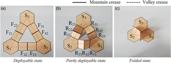
A single-closed-loop rigid origami mechanism model is proposed, which distributes along an equilateral triangle. The model consists of three congruent regular hexagon panels and six congruent rectangular panels. And it assumes that the thickness of the panel is zero and the stiffness is infinite. The centroid of hexagon panels S U (U = 1,2,3) coincides with the three vertices of the equilateral triangle, and the three edges of the triangle can be regarded as three kinematic chains L U connected by two rectangular panels F U1 and F U2 through the revolute joints R UV (V = 1,2,3) with two adjacent regular hexagonal panels. The connection relationship of each component is shown in Fig. 1.
Single-closed-loop origami mechanism.

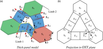
Based on the axis-shift approach, it is possible to convert the origami mechanism shown in Fig. 1 into a thick panel model, as seen in Fig. 2a. The DOF of the deployable unit is analysed by using the screw theory [Reference Huang, Zhao and Zhao43]. To begin, the upper surface of panel S1 is designated as the OXY plane, taking the intersection of R11 and R33 as the origin O, the X-axis coincides with the axis of the revolute joint R33, the Z-axis is perpendicular to the OXY plane upwards, and that of the Y-axis is determined by the right-hand rule.
Single-closed-loop deployable mechanism with thick panels.

The projection of the mechanism in the OXY plane is shown in Fig. 2b. According to the particular geometry and connection relationship of the components in the mechanism, the sufficient and necessary condition for the mechanism to form a closed loop is
 \begin{equation}\sum\limits_{U = 1}^3 {\angle {{\rm{A}}_U}{{\rm{B}}_U}{{\rm{C}}_U} = {{360}^ \circ }} \end{equation}
 $\angle {{\rm{A}}_U}{{\rm{B}}_U}{{\rm{C}}_U}$
is derived from the projection of the panels S
i
on the OXY plane, according to the basic properties of the projection, the value of ∠A
U
B
U
C
U
satisfy
 \begin{equation}\angle {{\rm{A}}_U}{{\rm{B}}_U}{{\rm{C}}_U} \le 120^\circ \end{equation}
Since the upper surface of the panel S1 is coplanar with the OXY plane, it can be obtained that
 \begin{equation}\angle {{\rm{A}}_1}{{\rm{B}}_1}{{\rm{C}}_1} = 120^\circ \end{equation}
If the panel S2 is not parallel to the OXY plane, it can be obtained that
 \begin{equation}\angle {{\rm{A}}_2}{{\rm{B}}_2}{{\rm{C}}_2} \lt 120^\circ \end{equation}
From Equations (1), (3) and (4), it can be obtained that
 \begin{equation}\angle {{\rm{A}}_3}{{\rm{B}}_3}{{\rm{C}}_3} \gt 120^\circ \end{equation}
Equation (5) contradicts with Equation (2), thus proving that the S2 is always parallel to the S1 during the movement of the mechanism. Similarly, it can be proved that the S3 is also always parallel to the panel S1.
Alternatively, the deployable unit can be regarded as a spatial parallel mechanism having two limbs, with S1 being a fixed platform and S2 being a moving platform. The limb 1 can be regarded as the kinematic chain L1, which contains three revolute joints R11, R12 and R13. And the limb 2 contains the kinematic chain L2 and L3 connected in series, comprising six revolute joints of R33, R32, R31, R23, R22 and R21.
The screw system of limb 1 is
 \begin{align}\left\{ \begin{array}{c@{\quad}c@{\quad}c@{\quad}c@{\quad}c@{\quad}c@{\quad}c}{{\boldsymbol{$}}_{11}^{}} = ( 1 & {\sqrt 3 } & 0 & ; & 0 & 0 & 0 )\\[4pt]{{\boldsymbol{$}}_{12}^{}} = ( 1 & {\sqrt 3 } & 0 & ;& { - \sqrt 3 l{\rm{s}}{\gamma _{11}}}& {l{\rm{s}}{\gamma _{11}}}& {l{\mathop{\rm c}\nolimits} {\gamma _{11}}} )\\[4pt]{{\boldsymbol{$}}_{13}^{}} = ( 1 & {\sqrt 3 } & 0 & ; & { - \sqrt 3 l\left( {{\rm{s}}{\gamma _{11}} - {\mathop{\rm s}\nolimits} {\gamma _{12}}} \right)}& {l\!\left( {{\rm{s}}{\gamma _{11}} - {\mathop{\rm s}\nolimits} {\gamma _{12}}} \right)}& {2l\!\left( {{\mathop{\rm c}\nolimits} {\gamma _{11}} + {\mathop{\rm c}\nolimits} {\gamma _{12}}} \right)} )\end{array} \right.\end{align}
The screw system of limb 2 is
 \begin{equation}\left\{ \begin{array}{lc@{\quad}c@{\quad}c@{\quad}c@{\quad}c@{\quad}c@{\quad}c}{{\boldsymbol{$}}_{21}^{} } =& ( 1 & { - \sqrt 3 } & 0 & ; & { - 2\sqrt 3 l{\mathop{\rm s}\nolimits} {\gamma _{11}}} & {2l{\mathop{\rm s}\nolimits} {\gamma _{11}}} & { - l\!\left( {{\mathop{\rm c}\nolimits} {\gamma _{11}} + {\mathop{\rm c}\nolimits} {\gamma _{12}}} \right)} )\\[4pt]{{\boldsymbol{$}}_{22}^{} } =& ( 1 & { - \sqrt 3 } & 0 & ; & {\sqrt 3 l{A_\gamma }} & {l{A_\gamma }} & {l{B_\gamma }} )\\[4pt]{{\boldsymbol{$}}_{23}^{} } =& ( 1 & { - \sqrt 3 } & 0 & ; & {\sqrt 3 l\!\left( {{\mathop{\rm s}\nolimits} {\gamma _{32}} - {\mathop{\rm s}\nolimits} {\gamma _{31}}} \right)} & {l\!\left( {{\mathop{\rm s}\nolimits} {\gamma _{32}} - {\mathop{\rm s}\nolimits} {\gamma _{31}}} \right)} & {2l\!\left( {{\mathop{\rm c}\nolimits} {\gamma _{31}} + {\mathop{\rm c}\nolimits} {\gamma _{32}}} \right)} )\\[4pt]{{\boldsymbol{$}}_{31}^{} } =& ( { - 1} & 0 & 0 & ; & 0 & {l\!\left( {{\mathop{\rm s}\nolimits} {\gamma _{32}} - {\mathop{\rm s}\nolimits} {\gamma _{31}}} \right)} & { - l\!\left( {{\mathop{\rm c}\nolimits} {\gamma _{31}} + {\mathop{\rm c}\nolimits} {\gamma _{32}}} \right)} )\\[4pt]{{\boldsymbol{$}}_{32}^{} } =& ( { - 1} & 0 & 0 & ; & 0 & { - l{\mathop{\rm s}\nolimits} {\gamma _{32}}} & { - l{\mathop{\rm c}\nolimits} {\gamma _{32}}} )\\[4pt]{{\boldsymbol{$}}_{33}^{} } = & ( { - 1} & 0 & 0 & ; & 0 & 0 & 0 )\end{array} \right.\end{equation}
where
 \begin{equation*}l = \sqrt {{d^2} + {c^2}} \end{equation*}
 \begin{equation*}{\gamma _{i1}} = {\tau _{i1}} - \arctan \frac{d}{c}\end{equation*}
 \begin{equation*}{\gamma _{i2}} = {\tau _{i2}} - \arctan \frac{d}{c}\end{equation*}
 \begin{equation*}{A_\gamma } = {\rm{s}}{\gamma _{22}} - {\rm{s}}{\gamma _{31}} + {\rm{s}}{\gamma _{32}}\end{equation*}
 \begin{equation*}{B_\gamma } = {\mathop{\rm c}\nolimits} {\gamma _{31}} + {\mathop{\rm c}\nolimits} {\gamma _{32}} - 2{\mathop{\rm c}\nolimits} {\gamma _{22}}\end{equation*}
τ U1 and τ U2 represent the acute angles between the panels F U1, F U2 and the OXY plane respectively; sγ and cγ represent sinγ and cosγ; c and d are the length and thickness of the rectangular panels.
From the Equation (5), it can be seen that the motion screw is linear independent, and the rank of the screw system of limb 1 is 3. According to Equation (7),
 $\boldsymbol{$}$
21 can be expressed as
 \begin{equation}{\boldsymbol{$}}_{21}^{} = {C_\gamma }\!\left( {{\mathop{\rm s}\nolimits} {\gamma _{31}}{\boldsymbol{$}}_{12}^{} - \left( {{\mathop{\rm s}\nolimits} {\gamma _{31}} - {\mathop{\rm s}\nolimits} {\gamma _{32}}} \right) {\boldsymbol{$}}_{32}^{} - {\mathop{\rm s}\nolimits} {\gamma _{32}}{\boldsymbol{$}}_{31}^{}} \right) + \left( {{D_\gamma } - 1} \right){\boldsymbol{$}}_{23}^{} - {D_\gamma }{\boldsymbol{$}}_{22}^{}\end{equation}
where
 \begin{align*}{C_\gamma } & = \frac{{ {\mathop{\rm c}\nolimits} {\gamma _{11}} {\mathop{\rm s}\nolimits} {\gamma _{22}} - 4 {\mathop{\rm c}\nolimits} {\gamma _{22}} {\mathop{\rm s}\nolimits} {\gamma _{11}} + {\mathop{\rm c}\nolimits} {\gamma _{12}} {\mathop{\rm s}\nolimits} {\gamma _{22}} - 2 {\mathop{\rm c}\nolimits} {\gamma _{22}} {\mathop{\rm s}\nolimits} {\gamma _{31}} + {\mathop{\rm c}\nolimits} {\gamma _{31}}{\mathop{\rm s}\nolimits} {\gamma _{22}} + 2 {\mathop{\rm c}\nolimits} {\gamma _{22}}{\mathop{\rm s}\nolimits} {\gamma _{32}} + {\mathop{\rm c}\nolimits} {\gamma _{32}}{\mathop{\rm s}\nolimits} {\gamma _{22}}}}{{2 {\mathop{\rm s}\nolimits} \left( {{\gamma _{31}} + {\gamma _{32}}} \right) {\mathop{\rm s}\nolimits} {\gamma _{22}}}}\\[5pt]{D_\gamma } & = \frac{{2 {\mathop{\rm s}\nolimits} {\gamma _{11}} + {\mathop{\rm s}\nolimits} {\gamma _{31}} - {\mathop{\rm s}\nolimits} {\gamma _{32}}}}{{ {\mathop{\rm s}\nolimits} {\gamma _{22}}}}\end{align*}
Therefore, there are five linearity-independent screws in limb 2, which has six screws. According to
 ${\boldsymbol{$}} \circ {{\boldsymbol{$}}^r} = 0$
[Reference Huang, Zhao and Zhao43], it can be solved that the motion screw systems of two limbs have the same reciprocal screw:
 \begin{equation*}{\boldsymbol{$} ^r} = \ \left( {0\ 0\ 0\ ;\ 0\ 0\ 1} \right)\end{equation*}
Hence, it is observed that the common constraint λ = 1. Furthermore, due to the presence of six motion screws in the motion screw system of limb 2, with a rank of 5, it can be deduced that there exists a passive DOF. In accordance with the modified G-K formula, the DOF of the mechanism can be determined:
 \begin{align*}M & = \left( {6 - \lambda } \right)\left( {q - \varepsilon - 1} \right) + \sum\limits_{t = 1}^g {{T_e} - \xi } \\[4pt] & = \left( {6 - 1} \right) \times \left( {9 - 9 - 1} \right) + 9 - 1\\[4pt] & = 3\end{align*}
where λ represents the number of common constraints, q represents the number of parts of the mechanism containing the frame,
 $\varepsilon$
represents the number of kinematical pairs, T
e
is the DOF of the eth motion pair, ξ represents the passive DOF.
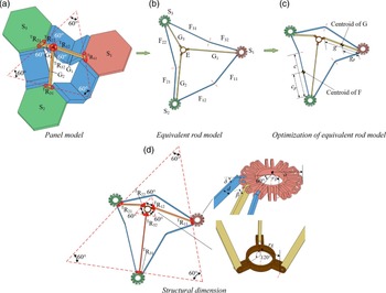
The construction of tetrahedral deployable unit (TDU).

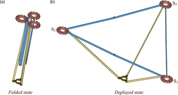
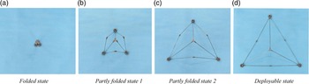
In the process of modular expansion, the DOF of the deployable unit is usually required to be as small as possible. A method to reduce the DOF from three to one is proposed as shown in Fig. 3a. Revolute joints TR11, TR21 and TR31 are used to connect rod G1, G2 and G3 on panels S1, S2 and S3, respectively. The other end of rod G1, G2 and G3 is connected to the panel E through revolute joints TR12, TR22 and TR32. The angular between the axes of the revolute joints TR11, TR21 and TR31, as well as the angular between the axes of the revolute joints TR12, TR22 and TR32, are 60°. The revolute joints on the same rod are parallel to each other. Figure 3 illustrates the equivalence of panel F to rod F, panel S to floral disc S, and panel E to floral disc E, leading to the creation of an equivalent rod model. In order to minimise the space occupied after the deployable unit is folded, the rod F is designed to be folded upward to obtain the mechanism shown in Fig. 3c. The S1, S2 and S3 are always coplanar during the movement of the mechanism, and the △S1S2S3 composed of its corresponding centroid is always an equilateral triangle, as shown in Fig. 4 [Reference Xu and Guan44]. In the Fig. 3c, c and g represent the length of F and G, c
p and g
p represent the length between the centroid and the revolute pair of F and G, respectively. In the Fig. 3d, r
s represents the distance between the centroid of the floral discs and the axis of the revolute joint,
 $\delta$
represents the acute angle between the F and the S,
 $\beta$
represents the acute angle between the G and the S.
2.2 Modular networking of deployable unit
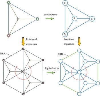
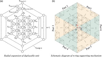
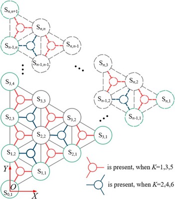
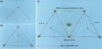
A deployable mechanism with a large scale can be constructed by interconnecting a sequence of deployable units in accordance with specific theory of mechanism design. According to the motion characteristics of the TDU, a grid-based networking construction method is proposed as follows: firstly, as shown in Fig. 5, the deployable unit is represented by an equilateral triangle, where three vertices S1, S2 and S3 of the triangle represent the centroid of the panels, respectively. Secondly, by sharing triangular vertices and adding RRR-constrained kinematic chains, a large-scale deployable mechanism can be formed so that the motion between modules can be transmitted without changing the DOF. Lastly, as shown in Fig. 6, according to the principle of planar mosaic, the plane can be divided into several graphic regions with the same area by using regular triangles, in which each regular triangle is a deployable unit. In the Fig. 6, ‘○’ represents the floral discs, and ‘—’ represents the generalised kinematic chain between the floral discs, which is similar to the topological graph of the mechanism.
Deployable sequence of TDU.

The sequence of rotational expansion.

Schematic diagram of radial expansion.

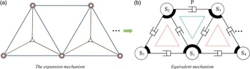
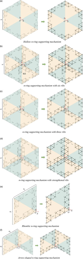
Due to △S1S2S3 is a regular triangle, the lengths of its sides, namely S1S2, S1S3 and S2S3, will remain equal during the motion of the mechanism. Consequently, the RRR-constraint kinematic chain can be considered equivalent to a prismatic joint, as shown in Fig. 7b. The same equivalent unit is constructed between two units sharing the same vertex and two kinematic chains, so that the motion can be transmitted and the DOF of the expanded mechanism is maintained at 1. More shapes can be generated via the expansion method described above, as shown in Fig. 8.
Equivalent expansion mechanism.

The supporting mechanism.

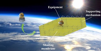
The equipment is arranged at the centre O of the supporting mechanism shown in the Fig. 9, and the shading membrane is fixed on the supporting mechanism. During the launch phase of the spacecraft, the supporting mechanism is fully folded, and the shading membrane is folded according to specific pre-compression creases [Reference Kamaliya, Shukla, Upadhyay and Mallikarachchi45–Reference Arya and Pellegrino47]. During the work phase, the supporting mechanism deploys and lifts the shading membrane.
The rendering of sunshield.

3.0 Kinematics analysis and prototype verification
3.1 Centroid motion analysis
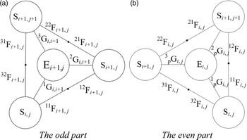
The supporting mechanism can be divided into six parts with a regular triangle profile, as shown in Fig. 6b. The initial part is represented by Fig. 10, whereas the six parts can be derived by rotating (K–1)π/3(K = 1∼6) rad in relation to the initial part. In the odd part (K = 1, 3 and 5) and the even part (K = 2, 4 and 6), the arrangement of E and G are different, as shown in Fig. 11.
Schematic diagram of initial part of the n-ring supporting mechanism.

The layout diagram of floral discs E and rod G in odd and even parts.

The position of any node (triangle vertex or the centroid of floral discs S) can be represented by vector
S
i,j
(i
 $\in$
[0, n], j
 $\in$
[1, n+1]), that is
 \begin{equation}{{\boldsymbol{S}}_{i,j}} = {\left[ {{X_{{{\rm{s}}_{i,j}}}},{Y_{{{\rm{s}}_{i,j}}}},{Z_{{{\rm{s}}_{i,j}}}}} \right]^{\rm{T}}}\end{equation}
The centroid of the S0,1 coincides with the origin. The internal centroid of floral discs of the initial part can be expressed by the nodes on the two edges starting from the origin as follows:
 \begin{equation}{{\boldsymbol{S}}_{i,j}} = {{\boldsymbol{S}}_{i - j + 1,1}} + {{\boldsymbol{S}}_{j - 1,j}}\end{equation}
where
 \begin{equation*}{{\boldsymbol{S}}_{i - j + 1,1}} = {\left[ {\sqrt 3 \left( {c\cos \delta + {r_S}} \right)\left( {i - j + 1} \right),\left( {c\cos \delta + {r_S}} \right)\left( {i - j + 1} \right),0} \right]^{\rm{T}}}\end{equation*}
 \begin{equation*}{{\boldsymbol{S}}_{j - 1,j}} = {\left[ {0,2\!\left( {j - 1} \right)\left( {{r_S} + c\cos \delta } \right),0} \right]^{\rm{T}}}\end{equation*}
According to Fig. 10, each part of the mechanism contains two kinds of triangles with different layout arrangements as shown in Fig. 11. Let △S i+1,j S i+1,j+1S i,j and △S i+1,j S i,j S i+1,j+1 be named D i+1, j and pD i, j , respectively. Each side of D i+1, j contains two rods F, whose position vector are
 \begin{equation}\left\{ \begin{array}{l}{}^{11}{{\boldsymbol{F}}_{i + 1,j}} = {{\boldsymbol{S}}_{i,j}} + {\left[ {\dfrac{{\sqrt 3 }}{2}\left( {{r_s} + {\xi _c}c\cos \delta } \right),\dfrac{1}{2}\left( {{r_s} + {\xi _c}c\cos \delta } \right), - {\xi _c}c\sin \delta } \right]^{\rm{T}}}\\[15pt]{}^{12}{{\boldsymbol{F}}_{i + 1,j}} = {{\boldsymbol{S}}_{i,j}} + {\left[ {\dfrac{{\sqrt 3 }}{2}\left( {{r_s} + \left( {1 + {\xi _c}} \right)c\cos \delta } \right),\dfrac{1}{2}\left( {{r_s} + \left( {1 + {\xi _c}} \right)c\cos \delta } \right), - {\xi _c}c\sin \delta } \right]^{\rm{T}}}\\[15pt]{}^{21}{{\boldsymbol{F}}_{i + 1,j}} = {{\boldsymbol{S}}_{i + 1,j}} + {\left[ { - \dfrac{{\sqrt 3 }}{2}\left( {{r_s} + {\xi _c}c\cos \delta } \right),\dfrac{1}{2}\left( {{r_s} + {\xi _c}c\cos \delta } \right), - {\xi _c}c\sin \delta } \right]^{\rm{T}}}\\[15pt]{}^{22}{{\boldsymbol{F}}_{i + 1,j}} = {{\boldsymbol{S}}_{i + 1,j}} + {\left[ { - \dfrac{{\sqrt 3 }}{2}\left( {{r_s} + \left( {1 + {\xi _c}} \right)c\cos \delta } \right),\dfrac{1}{2}\left( {{r_s} + \left( {1 + {\xi _c}} \right)c\cos \delta } \right), - {\xi _c}c\sin \delta } \right]^{\rm{T}}}\\[15pt]{}^{31}{{\boldsymbol{F}}_{i + 1,j}} = {{\boldsymbol{S}}_{i + 1,j + 1}} + {\left[ {0, - \left( {{r_s} + {\xi _c}c\cos \delta } \right), - {\xi _c}c\sin \delta } \right]^{\rm{T}}}\\[8pt]{}^{32}{{\boldsymbol{F}}_{i + 1,j}} = {{\boldsymbol{S}}_{i + 1,j + 1}} + {\left[ {0, - \left( {{r_s} + \left( {1 + {\xi _c}} \right)c\cos \delta } \right), - {\xi _c}c\sin \delta } \right]^{\rm{T}}}\end{array} \right.\end{equation}
where
 \begin{equation*}{\xi _c} = \frac{{{c_{\rm{p}}}}}{c}\end{equation*}
Therefore, the centroid positions of all F in D i+1, j of Part K can be expressed as
 \begin{equation}{}_{\rm{F}}^K{{\boldsymbol{I}}_{i + 1,j}} = \left[ {\begin{array}{*{20}{c}}{{{\boldsymbol{R}}_K}{}^{11}{{\boldsymbol{F}}_{i + 1,j}}}\quad {{{\boldsymbol{R}}_K}{}^{12}{{\boldsymbol{F}}_{i + 1,j}}}\quad {{{\boldsymbol{R}}_K}{}^{21}{{\boldsymbol{F}}_{i + 1,j}}} \quad {{{\boldsymbol{R}}_K}{}^{22}{{\boldsymbol{F}}_{i + 1,j}}}\quad {{{\boldsymbol{R}}_K}{}^{31}{{\boldsymbol{F}}_{i + 1,j}}}\quad {{{\boldsymbol{R}}_K}{}^{32}{{\boldsymbol{F}}_{i + 1,j}}}\end{array}} \right]\end{equation}
where
 \begin{equation*}{{\boldsymbol{R}}_K} = \left[ \begin{array}{c@{\quad}c@{\quad}c}{\cos \!\left( {\dfrac{{\left( {K - 1} \right){\rm{\pi }}}}{3}} \right)} & -\sin \!\left( {\dfrac{{\left( {K - 1} \right){\rm{\pi }}}}{3}} \right) & 0\\[9pt] \sin \!\left( {\dfrac{{\left( {K - 1} \right){\rm{\pi }}}}{3}} \right) & \cos \!\left( {\dfrac{{\left( {K - 1} \right){\rm{\pi }}}}{3}} \right) & 0\\[9pt] 0 & 0 & 1\end{array} \right]\end{equation*}
Then the centroid positions of F in Part K can be expressed as
 \begin{equation}{}_{\rm{F}}^K{\boldsymbol{D}} = \left[ {{}_{\rm{F}}^K{{\boldsymbol{I}}_{1,1}}} \quad {{}_{\rm{F}}^K{{\boldsymbol{I}}_{2,1}}} \quad {{}_{\rm{F}}^K{{\boldsymbol{I}}_{2,2}}} \quad \cdots \quad {{}_{\rm{F}}^K{{\boldsymbol{I}}_{n,n}}} \right]\end{equation}
In addition, it can be seen that the arrangement of the odd part and the even part of G and E is different. Therefore, it is necessary to calculate the centroid position vector of G and E in the supporting mechanism in different part.
In the odd part ( K = 1, 3 and 5):
G and E in the odd part are only arranged in the deployable unit D i+1, j , so the centroid position vectors of G are
 \begin{equation}\left\{ \begin{array}{l}{}_{}^1{{\boldsymbol{G}}_{i + 1,j}} = {{\boldsymbol{S}}_{i,j}} + {\left[ {\dfrac{1}{2}\left( {{r_s} + {\xi _g}g\cos \beta } \right),\dfrac{{\sqrt 3 }}{2}\left( {{r_s} + {\xi _g}g\cos \beta } \right), - {\xi _g}g\sin \beta } \right]^{\rm{T}}}\\[16pt]{}_{}^2{{\boldsymbol{G}}_{i + 1,j}} = {{\boldsymbol{S}}_{i + 1,j}} + {\left[ { - \left( {{r_s} + {\xi _g}g\cos \beta } \right),0, - {\xi _g}g\sin \beta } \right]^{\rm{T}}}\\[9pt]{}_{}^3{{\boldsymbol{G}}_{i + 1,j}} = {{\boldsymbol{S}}_{i + 1,j + 1}} + {\left[ {\dfrac{1}{2}\left( {{r_s} + {\xi _g}g\cos \beta } \right), - \dfrac{{\sqrt 3 }}{2}\left( {{r_s} + {\xi _g}g\cos \beta } \right), - {\xi _g}g\sin \beta } \right]^{\rm{T}}}\end{array} \right.\end{equation}
where
 \begin{equation*}{\xi _g} = \frac{{{g_p}}}{g}\end{equation*}
The centroid positions of all G in D i+1,j of Part K can be expressed as
 \begin{equation}{}_{\rm{G}}^K{{\boldsymbol{I}}_{i + 1,j}} = \left[ {{{\boldsymbol{R}}_K}{}_{}^1{{\boldsymbol{G}}_{i + 1,j}}} \quad {{{\boldsymbol{R}}_K}{}_{}^2{{\boldsymbol{G}}_{i + 1,j}}} \quad {{{\boldsymbol{R}}_K}{}_{}^3{{\boldsymbol{G}}_{i + 1,j}}} \right]\end{equation}
G of the odd part do not exist in the deployable unit pD i,j , which are expressed as
 \begin{equation}{}_{{\rm{Gp}}}^K{{\boldsymbol{I}}_{i,j}} = \left[ {{{\boldsymbol{R}}_K}\textbf{0}}\quad {{{\boldsymbol{R}}_K}\textbf{0}} \quad {{{\boldsymbol{R}}_K}\textbf{0}} \right]\end{equation}
where 0 represents a null matrix with 3 rows and 1 column.
The centroid positions of E can be expressed as
 \begin{equation}{}^{}{{\boldsymbol{E}}_{i + 1,j}} = {{\boldsymbol{S}}_{i + 1,j}} + {\left[ { - \left( {{r_s} + {r_E} + g\cos \beta } \right),0, - g\sin \beta } \right]^{\rm{T}}}\end{equation}
Therefore, the centroids position of E in D i+1,j of Part K can be expressed as
 \begin{equation}{}_{\rm{E}}^K{{\boldsymbol{I}}_{i + 1,j}} = \left[ {{{\boldsymbol{R}}_K}{{\boldsymbol{E}}_{i + 1,j}}} \right]\end{equation}
E of the odd part do not exist in the deployable unit pD i, j , which are expressed as
 \begin{equation}{}_{{\rm{Ep}}}^K{{\boldsymbol{I}}_{i,j}} = \left[ {{{\boldsymbol{R}}_K}\textbf{0}} \right]\end{equation}
In the even part ( K = 2, 4 and 6):
G and E of the even part are only arranged in the deployable unit pD i, j , so the centroid positions vector of G are
 \begin{equation}\left\{ \begin{array}{l}{}_{\rm{p}}^1{{\boldsymbol{G}}_{i,j}} = {{\boldsymbol{S}}_{i,j}} + {\left[ { - \dfrac{1}{2}\left( {{r_s} + {\xi _g}g\cos \beta } \right),\dfrac{{\sqrt 3 }}{2}\left( {{r_s} + {\xi _g}g\cos \beta } \right), - {\xi _g}g\sin \beta } \right]^{\rm{T}}}\\[15pt]{}_{\rm{p}}^2{{\boldsymbol{G}}_{i,j}} = {{\boldsymbol{S}}_{i + 1,j + 1}} + {\left[ { - \dfrac{1}{2}\left( {{r_s} + {\xi _g}g\cos \beta } \right), - \dfrac{{\sqrt 3 }}{2}\left( {{r_s} + {\xi _g}g\cos \beta } \right), - {\xi _g}g\sin \beta } \right]^{\rm{T}}}\\[15pt]{}_{\rm{p}}^3{{\boldsymbol{G}}_{i,j}} = {{\boldsymbol{S}}_{i + 1,j}} + {\left[ {\left( {{r_s} + {\xi _g}g\cos \beta } \right),0, - {\xi _g}g\sin \beta } \right]^{\rm{T}}}\end{array} \right.\end{equation}
Therefore, the centroid positions of G in the even part in p D i, j of Part K can be expressed as
 \begin{equation}{}_{{\rm{Gp}}}^K{{\boldsymbol{I}}_{i,j}} = \left[ {{{\boldsymbol{R}}_K}\,{}_{\rm{p}}^1{{\boldsymbol{G}}_{i,j}}} \quad{{{\boldsymbol{R}}_K}\,{}_{\rm{p}}^2{{\boldsymbol{G}}_{i,j}}} \quad {{{\boldsymbol{R}}_K}\,{}_{\rm{p}}^3{{\boldsymbol{G}}_{i,j}}} \right]\end{equation}
G of the even part do not exist in the deployable unit D i+1,j , which are expressed as
 \begin{equation}{}_{\rm{G}}^K{{\boldsymbol{I}}_{i + 1,j}} = \left[ {{{\boldsymbol{R}}_K}\textbf{0}} \quad {{{\boldsymbol{R}}_K}\textbf{0}} \quad {{{\boldsymbol{R}}_K}\textbf{0}} \right]\end{equation}
The centroid positions of E can be expressed as
 \begin{equation}{}^{\rm{p}}{{\boldsymbol{E}}_{i,j}} = {{\boldsymbol{S}}_{i + 1,j}} + {\left[ {\left( {{r_s} + {r_E} + g\cos \beta } \right),0, - c\sin \beta } \right]^{\rm{T}}}\end{equation}
Therefore the centroid position in the even part of the E in p D i, j of Part K can be expressed as
 \begin{equation}{}_{{\rm{Ep}}}^K{{\boldsymbol{I}}_{i,j}} = \left[ {{{\boldsymbol{R}}_K}{}^{\rm{p}}{{\boldsymbol{E}}_{i,j}}} \right]\end{equation}
E of the even part do not exist in the deployable unit D i+1, j , which are expressed as
 \begin{equation}{}_{\rm{E}}^K{{\boldsymbol{I}}_{i + 1,j}} = \left[ {{{\boldsymbol{R}}_K}\textbf{0}} \right]\end{equation}
Then the centroid positions of G and E in Part K can be expressed as
 \begin{equation}{}_{\rm{G}}^K{\boldsymbol{D}} = \left[ {{}_{\rm{G}}^K{{\boldsymbol{I}}_{1,1}}} \quad {{}_{\rm{G}}^K{{\boldsymbol{I}}_{2,1}}} \quad {{}_{\rm{G}}^K{{\boldsymbol{I}}_{2,2}}}\quad \cdots \quad {{}_{\rm{G}}^K{{\boldsymbol{I}}_{n,n}}} \quad {{}_{{\rm{Gp}}}^K{{\boldsymbol{I}}_{1,1}}} \quad {{}_{{\rm{Gp}}}^K{{\boldsymbol{I}}_{2,1}}} \quad {{}_{{\rm{Gp}}}^K{{\boldsymbol{I}}_{2,2}}} \quad \cdots \quad {{}_{{\rm{Gp}}}^K{{\boldsymbol{I}}_{n - 1,n - 1}}} \right]\end{equation}
 \begin{equation}{}_{\rm{E}}^K{\boldsymbol{D}} = \left[ {{}_{\rm{E}}^K{{\boldsymbol{I}}_{1,1}}} \quad {{}_{\rm{E}}^K{{\boldsymbol{I}}_{2,1}}} \quad {{}_{\rm{E}}^K{{\boldsymbol{I}}_{2,2}}} \quad \cdots \quad {{}_{\rm{E}}^K{{\boldsymbol{I}}_{n,n}}} \quad {{}_{{\rm{Ep}}}^K{{\boldsymbol{I}}_{1,1}}} \quad {{}_{{\rm{Ep}}}^K{{\boldsymbol{I}}_{2,1}}} \quad {{}_{{\rm{Ep}}}^K{{\boldsymbol{I}}_{2,2}}} \quad \cdots \quad {{}_{{\rm{Ep}}}^K{{\boldsymbol{I}}_{n - 1,n - 1}}} \right]\end{equation}
Then the centroid positions of S can be expressed as
 \begin{equation}{}_{\rm{S}}^K{\boldsymbol{D}} = \left[{{{\boldsymbol{R}}_K}{}^K{{\boldsymbol{S}}_{0,1}}} \quad {{{\boldsymbol{R}}_K}{}^K{{\boldsymbol{S}}_{1,1}}} \quad {{{\boldsymbol{R}}_K}{}^K{{\boldsymbol{S}}_{1,2}}} \quad {{{\boldsymbol{R}}_K}{}^K{{\boldsymbol{S}}_{2,1}}} \quad {{{\boldsymbol{R}}_K}{}^K{{\boldsymbol{S}}_{2,2}}} \quad {{{\boldsymbol{R}}_K}{}^K{{\boldsymbol{S}}_{2,3}}} \quad \cdots \quad {{{\boldsymbol{R}}_K}{}^K{{\boldsymbol{S}}_{n,n + 1}}}\right]\end{equation}
In summary, the centroid positions of each component in the Part K can be expressed as
 \begin{equation}{{\boldsymbol{D}}_K} = \left[ {{}_{\rm{F}}^K{\boldsymbol{D}}} \quad {{}_{\rm{G}}^K{\boldsymbol{D}}} \quad {{}_{\rm{E}}^K{\boldsymbol{D}}} \quad {{}_{\rm{S}}^K{\boldsymbol{D}}} \right]\end{equation}
In the n-ring supporting mechanism, the centroid positions of F, G and E can be expressed by a matrix with 18 rows and ((15n 2+13n–2)/2) columns:
 \begin{equation}{\boldsymbol{M}} = {\left[ {{{\boldsymbol{D}}_1}} \quad {{{\boldsymbol{D}}_2}} \quad \cdots \quad {{{\boldsymbol{D}}_6}} \right]^{\rm{T}}}\end{equation}
The velocity and acceleration can be expressed as
 \begin{equation}\dot{\boldsymbol{M}} = {\left[ {{{\dot{\boldsymbol{D}}}_1}} \quad {{{\dot{\boldsymbol{D}}}_2}} \quad \cdots \quad {{{\dot{\boldsymbol{D}}}_6}}\right]^{\rm{T}}}\end{equation}
and
 \begin{equation}\ddot{\boldsymbol{M}} = {\left[ {\ddot{\boldsymbol{D}}}_1 \quad {\ddot{\boldsymbol{D}}}_2 \quad \cdots \quad {\ddot{\boldsymbol{D}}}_6 \right]^{\rm{T}}}\end{equation}
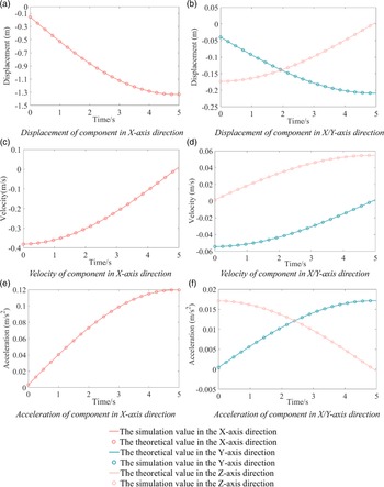
Centroid motion law of F3,2 in D2,2 of Part 3.

Taking the solid supporting mechanism with n = 2 as an example, the active component is set to 1,1F1,1, and the angular velocity is 18°/s. The virtual prototype is established in Solidworks, and the motion simulation is compared with the calculation results of Matlab. The motion curves of the centroid of F3,2 in D2,2 of Part 3 are obtained, as shown in Fig. 12. By analysing the motion curves, the theoretical values of displacement, velocity and acceleration are completely consistent with the simulation values, which verifies the correctness of the kinematic model of the mechanism established in this paper, and the velocity and acceleration values are not mutated. The motion process of the mechanism is stable and has no large impact.
3.2 Analysis of folding ratio
For the deployable mechanism, the folding ratio is one of the important indexes to evaluate the performance of the mechanism. The mechanism with higher folding ratio reach a larger workspace after fully deploying in a limited initial space. Some deployable mechanisms evaluate the size of the workspace with the expanded envelope area, such as the deployable supporting truss mechanism. The folding ratio can be expressed as
 \begin{equation}{\eta _{\rm{L}}} = \frac{{{S_{\rm{D}}}}}{{{S_{\rm{F}}}}}\end{equation}
where S D and S F represent the maximum envelope area and the minimum envelope area of the supporting mechanism on the OXY plane in the deployable state and the folded state, respectively.
According to the Equation (43), the folding ratio of the n-ring supporting mechanism can be expressed as
 \begin{equation}\eta = \frac{{6\sqrt 3 {{\left( {\dfrac{{\sqrt 3 }}{3}a + \left( {{r_{\rm{S}}} + c} \right)n} \right)}^2}}}{{6\sqrt 3 {{\left( {\dfrac{{\sqrt 3 }}{3}a + \left( {{r_{\rm{S}}} + d} \right)n} \right)}^2}}}\end{equation}
and further obtained
 \begin{equation}\eta = {\left( {\frac{{\sqrt 3 a + 3n\!\left( {{r_{\rm{S}}} + c} \right)}}{{\sqrt 3 a + 3n\!\left( {{r_{\rm{S}}} + d} \right)}}} \right)^2}\end{equation}
According to the Equation (35), the folding ratio grows with the increase of c and the decrease of d. Derivation of a on Equation (35) yields
 \begin{equation}\frac{{{\rm{d}}\eta }}{{{\rm{d}}a}}{\rm{ = }} - \frac{{6 n ( {c - d})( {3 a + c n + n {r_{\rm{s}}}} )}}{{\left( {3 a + d n + n {r_{\rm{s}}}} \right)}^3}\end{equation}
Equation (34) shows that when the thickness d of the rod is greater than the length c of the rod, the folding ratio of the mechanism is less than 1. Therefore, the design should ensure that c > d, which can make
 \begin{equation*}\frac{{{\rm{d}}\eta }}{{{\rm{d}}a}} \lt 0\end{equation*}
Therefore, the folding ratio decreases with the increase of d. Derivation of r s and n, respectively, on Equation (35) yields
 \begin{equation}\frac{{{\rm{d}}\eta }}{{{\rm{d}}{r_{\rm{s}}}}} = - \frac{{2 {n^2} ( {c - d}) \left( {3 a + c n + n {r_{\rm{s}}}} \right)}}{{{{\left( {3 a + d n + n {r_{\rm{s}}}} \right)}^3}}} \lt 0\end{equation}
and
 \begin{equation}\frac{{{\rm{d}}\eta }}{{{\rm{d}}n}} = \frac{{6 a ( {c - d}) \left( {3 a + c n + n {r_{\rm{s}}}} \right)}}{{{{\left( {3 a + d n + n {r_{\rm{s}}}} \right)}^3}}} \gt 0\end{equation}
Equations (37) and (38) show that the folding ratio grows with the decrease of r
s
and the increase of n. The definition domains of each parameter are defined as: n
 $\in$
[1,3,6], c
 $\in$
[0.1,0.35], r
s
 $\in$
[0.01,0.035], a
 $\in$
[0.04,0.06] and d
 $\in$
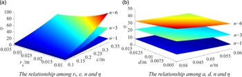
[0.005,0.015]. According to Equation (35) and the parameter of components, the diagram which can express the relationship among
 $\eta$
, n, c, r
s
, a and d can be obtained by Matlab. As shown in Fig. 13, the folding ratio is positively correlated to c and n, and negatively correlated to d, a and r
s, which verify the correctness of above analysis.
The diagram of folding ratio.

Connection relationship.

The parameters of components.

3.3 Prototype verification
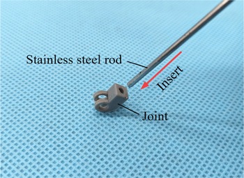
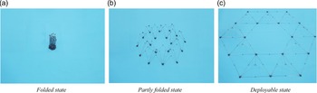
A hollow two-ring physical prototype of supporting mechanism with folding ratio of 45.8 was established based on 3D-print technology. The rod is assembled from joints and prefabricated stainless steel rods. The joints and floral discs are both 3D printed from poly lactic acid (PLA), with a printing accuracy of 0.02 mm. The diameter of the stainless steel rod is 2 mm. The construction process of physical prototype is as follows:
-
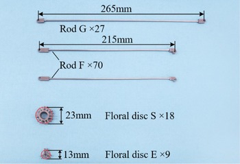
STEP 1: The joints and the stainless steel rods are assembled to construct the rods G and the rods F, as shown in Fig. 14. The parameters of the components are shown in Fig. 15.
-
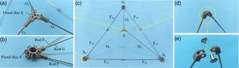
STEP 2: The basic unit is assembled according to the connection relationship of each component in Section 2.1 as shown in Fig. 16(c), and the specific connection method is shown in the Fig. 16(a), (b), (d) and (e). The deployable process of the basic deployable unit is shown in Fig. 17.
-
STEP 3: The basic deployable units are expanded according to the method in Section 2.2, as shown in Fig. 18. By the same way, a hollow two-ring physical prototype of supporting mechanism is obtained, and the deployable process is shown in Fig. 19.
The prototype moves smoothly and reliably during the deployable process, which verified the correctness of the proposed deployable unit expansion method for constructing supporting mechanisms in this paper, providing a reference for the subsequent research work of the supporting mechanism of the sunshield.
Assembly relationship of basic deployable unit.

Deployable process of basic deployable unit.

The basic deployable units expansion.

Deployable process of physical prototype.

4.0 Dynamics analysis
4.1 Dynamic modeling and simulation verification of supporting mechanism
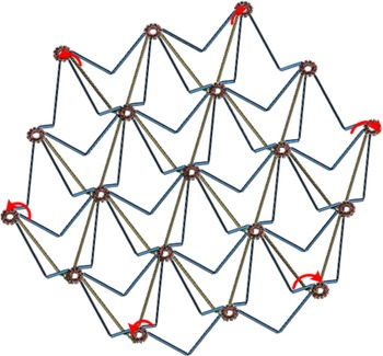
On account of supporting mechanism has one DOF, according to the mechanisms and machine theory, it can be known that only one drive device can be added to make the determined motion. However, in order to improve the deployment reliability of the mechanism, multiple torsion springs are generally added, and the elastic potential energy stored in the folded torsional springs is used to drive the mechanism to deploy. The mechanism has only one set of independent generalised coordinates, the input angle
 $\delta$
is selected as the generalised coordinate, and the dynamic equation can be established according to Lagrange equation as follows:
 \begin{equation}\frac{{\rm{d}}}{{{\rm{d}}t}}\frac{{\partial {E_v}}}{{\partial \dot \delta }} - \frac{{\partial {E_v}}}{{\partial \delta }} + \frac{{\partial {E_p}}}{{\partial \delta }} = Q\end{equation}
where E v , E p and Q are the kinetic energy, potential energy, and generalised force of the supporting mechanism, respectively.
If a floral discs S is fixed of supporting mechanism, such as S0,1 shown in Fig. 10, the mechanism in the process of deployment, all the moving components can be divided into three categories according to the characteristics of motion: translational motion (S and E), fixed-axis rotation (F and G, also called inner rods, are connected to S0,1.) and compound motion (except for the F and G which are connected to the S0,1, also called outer rods). In order to facilitate the calculation of the total kinetic energy between various components, the compound motion of the rod is divided into movement and rotation.
The total kinetic energy produced by the translation of F can be expressed as
 \begin{equation}{}^{\rm{F}}{E_{v1}} = \frac{1}{2}{m_{\rm{F}}}\sum\limits_{{A_{\rm{F}}}{\rm{ = }}1}^3 {\sum\limits_{{B_{\rm{F}}} = 1}^{3\!\left( {1 + n} \right)n} {{}^{\rm{F}}w{}_{{A_{\rm{F}}},{B_{\rm{F}}}}} } \end{equation}
where F
w
AF,BF
 $\in$
W
F
 \begin{equation} \boldsymbol{W}_{\textrm{F}} = \sum^{6}_{k=1} \left({}^{K}_{\textrm{F}}\boldsymbol{B}\bullet \boldsymbol{H}_{\textrm{F}}\right)\end{equation}
 \begin{equation}{}^{K}_{\textrm{F}}\boldsymbol{B} = {}^{K}_{\textrm{F}}\boldsymbol{D}\bullet {}^{K}_{\textrm{F}}\boldsymbol{D}\end{equation}
H F represents a matrix with the same dimension as the matrix F K D and its internal elements correspond to the internal elements of K F D one by one. In the matrix H F, the element ‘1’ represents the component in the mechanism, and the element ‘0’ represents the component that needs to be deleted.
The total kinetic energy produced by the rotation of F can be expressed as
 \begin{equation}{}^{\rm{F}}{E_{v2}} = \frac{1}{2}\left( {{N_{{\rm{F1}}}}{J_{{\rm{F}}1}} + {N_{{\rm{F2}}}}{J_{{\rm{F}}2}}} \right){\dot \delta ^2}\end{equation}
where J F1 and J F2 represents the rotational inertia of F belonging to the inner rods and the rotational inertia of F belonging to the outer rods in the global coordinate system, N F1 is the quantity of F belonging to the inner rods, N F2 is the quantity of F belonging to the outer rods.
Therefore, the total kinetic energy generated by F is
 \begin{equation}{}^{\rm{F}}{E_v} = {}^{\rm{F}}{E_{v1}} + {}^{\rm{F}}{E_{v2}}\end{equation}
The total kinetic energy produced by the translation of G can be expressed as
 \begin{equation}{}^{\rm{G}}{E_v} = \frac{1}{2}{m_{\rm{G}}}\sum\limits_{{A_{\rm{G}}}{\rm{ = }}1}^3 {\sum\limits_{{B_{\rm{G}}} = 1}^{\frac{{3\!\left( {1 + n} \right)n}}{2}} {{}^{\rm{G}}w{}_{{A_{\rm{G}}},{B_{\rm{G}}}}} } \end{equation}
where G
w
AG,BG
 $\in$
W
G
 \begin{equation} \boldsymbol{W}_{\textrm{G}} = \sum^{6}_{k=1} \left({}^{K}_{\textrm{G}}\boldsymbol{B}\bullet \boldsymbol{H}_{\textrm{G}}\right)\end{equation}
 \begin{equation}{}^{K}_{\textrm{G}}\boldsymbol{B} = {}^{K}_{\textrm{G}}\boldsymbol{D}\bullet {}^{K}_{\textrm{G}}\boldsymbol{D}\end{equation}
The total kinetic energy produced by the rotation of G can be expressed as
 \begin{equation}{}^{\rm{G}}{E_{v2}} = \frac{1}{2}\left( {{N_{{\rm{G1}}}}{J_{{\rm{G}}1}} + {N_{{\rm{G2}}}}{J_{{\rm{G}}2}}} \right){\dot \beta ^2}\end{equation}
where J G1 and J G2 represents the rotational inertia of G belonging to the inner rods and the rotational inertia of G belonging to the outer rods in the global coordinate system, N G1 is the quantity of G belonging to the inner rods, N G2 is the quantity of G belonging to the outer rods.
Therefore, the total kinetic energy generated by G is
 \begin{equation}{}^{\rm{G}}{E_v} = {}^{\rm{G}}{E_{v1}} + {}^{\rm{G}}{E_{v2}}\end{equation}
The total kinetic energy of S is expressed as
 \begin{equation}{}^{\rm{S}}{E_v} = \frac{1}{2}{m_{\rm{S}}}\sum\limits_{{A_{\rm{S}}}{\rm{ = }}1}^3 {\sum\limits_{{B_{\rm{S}}} = 1}^{\frac{{\left( {1 + n} \right)\left( {n + 2} \right)}}{2}} {{}^{\rm{S}}w{}_{{A_{\rm{S}}},{B_{\rm{S}}}}} } \end{equation}
where S
w
AS, BS
 $\in$
W
S
 \begin{equation} \boldsymbol{W}_{\textrm{S}} = \sum^{6}_{k=1} \left({}^{K}_{\textrm{S}}\boldsymbol{B}\bullet \boldsymbol{H}_{\textrm{S}}\right)\end{equation}
 \begin{equation}{}^{K}_{\textrm{S}}\boldsymbol{B} = {}^{K}_{\textrm{S}}\boldsymbol{D}\bullet {}^{K}_{\textrm{S}}\boldsymbol{D}\end{equation}
The total kinetic energy of E is expressed as
 \begin{equation}{}^{\rm{E}}{E_v} = \frac{1}{2}{m_{\rm{E}}}\sum\limits_{{A_{\rm{E}}}{\rm{ = }}1}^3 {\sum\limits_{{B_{\rm{E}}} = 1}^{\frac{{{n^2} + n}}{2}} {{}^{\rm{E}}w{}_{{A_{\rm{E}}},{B_{\rm{E}}}}} } \end{equation}
where E
w
AE, BE
 $\in$
W
E
 \begin{equation} \boldsymbol{W}_{\textrm{E}} = \sum^{6}_{k=1} \left({}^{K}_{\textrm{E}}\boldsymbol{B}\bullet \boldsymbol{H}_{\textrm{E}}\right)\end{equation}
 \begin{equation}{}^{K}_{\textrm{E}}\boldsymbol{B} = {}^{K}_{\textrm{E}}\boldsymbol{D}\bullet {}^{K}_{\textrm{E}}\boldsymbol{D}\end{equation}
In summary, the total kinetic energy of the n-ring supporting mechanism is
 \begin{equation}{E_v} = {}^{\rm{F}}{E_v} + {}^{\rm{G}}{E_v} + {}^{\rm{S}}{E_v} + {}^{\rm{E}}{E_v}\end{equation}
Assuming that the torsion springs are added to the revolute joints between the floral discs S and the rod F of the supporting mechanism, and considering that the application environment of the supporting mechanism has no gravity effect, only the elastic potential energy of the mechanism is considered here. Consequently, the total potential energy of the supporting mechanism is expressed as
 \begin{equation}{E_{\rm{p}}} = \frac{1}{2}\sum\limits_{u = 1}^\varsigma {{k_u}{{\left( {{\mu _{u0}} - {\delta _0} + \delta } \right)}^2}} \end{equation}
where k
u
and μ
u0 represent the stiffness and initial compression of the u-th torsion spring,
 $\delta_0$
represents the initial angle, ζ represents the quantity of torsion springs installed.
The following is an example of a double-ring supporting mechanism (n = 2). Since F of the six parts of the supporting mechanism is rotated from the initial part, when calculating the total kinetic energy generated by the movement of the F, there will be 11F i+1,1, 12F i+1,1 repeated calculations at the junction of the two adjacent parts. The elements in H F are
 \begin{equation}{}^{\rm{F}}{h_{P,1 + Q}} = {}^{\rm{F}}{h_{P,2 + Q}} = {}^{\rm{F}}{h_{P,6}} = 0\end{equation}
where
 ${}^{\rm{F}}h \in {{\boldsymbol{H}}_{\rm{F}}}$
,
 $Q = \sum\limits_{q = 0}^i {6q} $
,
 $i \in \left[ {0,n} \right]$
,
 $P \in \left[ {1,3} \right]$
, and the others are 1. When calculating the kinetic energy generated by the movement of G, the G connected to the S0,1 is not calculated. Therefore, the elements in
H
G are
 \begin{equation}{}^{\rm{G}}{h_{P,1}} = 0\end{equation}
where
 ${}^{\rm{G}}{h_{P,1}} \in {{\boldsymbol{H}}_{\rm{G}}}$
,
 $P \in \left[ {1,3} \right]$
, and the others are 1. When calculating the kinetic energy generated by the movement of S, there will be S
i,1 repeated calculations at the junction of the two adjacent parts. The elements in
H
S are
 \begin{equation}{}^{\rm{S}}{h_{P,M}} = 0\end{equation}
where
 ${}^{\rm{S}}{h_{P,M}} \in {{\boldsymbol{H}}_{\rm{S}}}$
,
 $P \in \left[ {1,3} \right]$
,
 $M = \sum\limits_{q{\rm{ = 0}}}^{{i_{\rm{s}}}} q $
,
 ${i_{\rm{s}}} \in \left[ {1,n} \right]$
, and the others are 1, all elements in matrix
H
E are 1.
The quantities of F and G with compound motions are
 \begin{equation}{N_{{\rm{F2}}}} = 18{n^2} + 6n - 6\end{equation}
 \begin{equation}{N_{{\rm{G2}}}} = 9{n^2} - 3\end{equation}
N F1 and N G1 are 6 and 3, respectively.
The Equations (58), (59), and (60) are substituted into Equations (41), (46) and (51), respectively; Equation (61) and N
F1, Equation (62) and N
G1 are substituted into Equations (43) and (48), respectively,
H
E is substituted into Equation (54), so that the total kinetic energy of each component can be calculated. Finally, Equations (56) and (57) are substituted into Equation (39). The change value of
 $\delta$
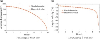
with time under the driving action of ζ torsion springs can be obtained by solving the differential equation. A set of structural parameters and dynamic parameters of the supporting mechanism are given, as shown in Table 1. The simulation model is established, and the torsion springs are installed at the revolute joints of the mechanism at six positions, as shown in Fig. 20, and the simulation is performed for 5.75 s. The theoretical and simulation law of motion about
 $\delta$
can be obtained by Matlab and Solidworks, respectively, as shown in Fig. 21.
Parameters of the components

Position of the torsion springs.

The relationship among
 $\delta$
,
 $\dot{\delta}$
and t.

It can be seen from Fig. 21 that the theoretical and simulation value of
 $\delta$
under the action of torsion spring drive are completely consistent, which verifies the correctness of the dynamic model of the mechanism established in this paper. The angular velocity increases slowly in the first 5 s and suddenly increases from 5 s.
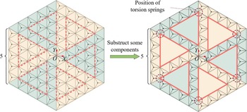
When calculating the total kinetic energy of the supporting mechanism with ribs, the kinetic energy of some components can be subtracted from the solid supporting mechanism, which corresponds to the change of the matrix H F, H G, H S and H E, the quantity of F and G in the equation. For example, the mechanism shown in Fig. 22 can be formed by removing the components in the wireframe from the mechanism. The parameters of each component are shown in Table 1, and the masses of the solid supporting mechanism and the supporting mechanism with ribs are 102.704 kg and 76.043 kg, respectively. The mass of supporting mechanism with ribs relative to solid supporting mechanism is reduced by 26%. Some parameters can be obtained: n = 5, N F2 = 366, N G2 = 141, N F1 = 6 and N G1 = 3. All the parameters of components are the same as in Table 1, expect for the torsion springs. The torsion springs are installed at the revolute joints connecting S4,5 and 31F4,4 shown in Fig. 22, and the parameters of the torsion springs are shown in Table 2.
The parameters of torsion springs

Construction of the 5-ring supporting mechanism with six ribs.

The elements in matrix H F are
 \begin{equation*}{}^{\rm{F}}{h_{P,{Q_{\rm{F}}}}} = 0\end{equation*}
where P
 $\in$
[1,3], Q
F
 $\in$
([1,2] ∪ [6,…,10] ∪ [19,…,28] ∪ [37,38] ∪ [41,…,44] ∪ [47,…,50] ∪ [61,62), and the others are 1.
The elements in matrix H G are
 \begin{equation*}{}^{\rm{G}}{h_{P,{Q_{\rm{G}}}}} = 0\end{equation*}
where P
 $\in$
[1,3], Q
G
 $\in$
([1] ∪ [4–6] ∪ [10,…,15] ∪ [19,27] ∪ [49,51] ∪ [55,60), and the others are 1.
The elements in matrix H E are
 \begin{equation*}{}^{\rm{E}}{h_{P,{Q_{\rm{E}}}}} = 0\end{equation*}
where P
 $\in$
[1,3], Q
E
 $\in$
([2] ∪ [4,5] ∪ [7–9] ∪ [17] ∪ [19,20), and the others are 1.
The elements in matrix H S are
 \begin{equation*}{}^{\rm{G}}{h_{P,{Q_{\rm{S}}}}} = 0\end{equation*}
where P
 $\in$
[1,3], Q
S
 $\in$
([1,2] ∪ [4] ∪ [7,8] ∪ [11,12]), and the others are 1.
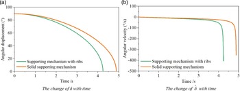
Lastly, under the same driving conditions, the motion law diagrams of two kinds of mechanisms are drawn, as shown in Fig. 23. The supporting mechanism with ribs and the solid supporting mechanism took 4.21 s and 4.90 s from the folded state to the deployable state. Therefore, the supporting mechanism with ribs is easier to be driven than solid supporting mechanism.
The relationship among
 $\delta$
,
 $\dot{\delta}$
and t.

4.2. The influence of torsion springs on the deployment of the supporting mechanism
Since the supporting mechanism of the sunshield is driven by the torsion springs, it is necessary to study the influence of parameters on the deployment of the mechanism. The basic parameters of the torsion springs in the mechanism include the quantity, position, stiffness and initial compression.
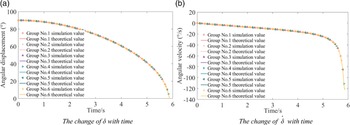
In order to analyse the influence of the combination of torsion springs with different quantities and different stiffnesses on the deployment motion of the mechanism, the total stiffness of the torsion springs in the simulation model is unchanged, and different quantities (1, 3, 6, 12 and 18) and different stiffnesses of torsion springs are selected to drive mechanism. The stiffnesses and position of the torsion springs are shown in Table 3, and the curves of
 $\delta$
is shown in Fig. 24. It shows that when the initial compression and total stiffness of torsion springs are the same, the combination of torsion springs with different quantities and different stiffnesses have the same driving effect on the deployment of the mechanism.
Quantities, stiffnesses and position of torsion springs

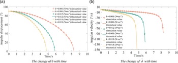
Let the quantity, initial compression and the position of torsion springs in the mechanism remain unchanged, the total stiffnesses of torsion springs are 0.006 N·m/°, 0.012 N·m/° and 0.018 N·m/°, to obtain the effect of the total stiffnesses of torsion springs on the deployment of mechanism as shown in Fig. 25. The figure shows that the greater the total stiffness of the torsion spring contained in the mechanism, the shorter the time taken for the mechanism to deploy in place, and the faster the mechanism deploys. Therefore, by reasonably selecting the total stiffness of the torsion spring, it is possible to control the time required for the mechanism to deploy in place, that is, to control the deploying speed of the mechanism, and thus reduce the impact of the mechanism when deploying in place.
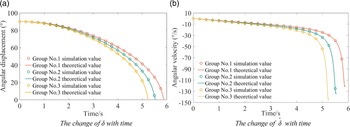
In order to analyse the effect of the initial compression of torsion springs on the deployment of the mechanism, the quantity of torsion spring, the total stiffness and the position are kept constant, and the torsion springs with the initial compression of 90°, 100°, and 110° are selected to drive the mechanism to deploy, respectively. The torsion spring parameters are shown in Gr. 1, Gr. 2 and Gr. 3 in Table 4, and the relationship between
 $\delta$
and t is shown in Fig. 26. It can be seen that as the initial compression increases, the time for the mechanism to deploy in place is shorter.
Quantities of torsion springs, initial compression, stiffness and position

The influence of the number and position of torsion springs on the deployment of the mechanism.

The influence of the total stiffness on the deployment of the mechanism.

The influence of the initial compression on the deployment of the mechanism.

To analyse the effect of torsion spring stiffness on the deployment of the mechanism when the initial compression of the torsion spring is less than
 $\delta_0$
(to ensure that the folding ratio of the mechanism is as large as possible, it should be
 $\delta_0$
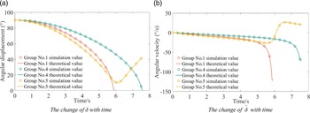
= 90°), six torsion springs with different initial compression are added to the simulation model of the mechanism, and the deployment of the mechanism is analysed. The parameters of the torsion springs are shown in Gr. 1, Gr. 4 and Gr. 5 in Table 4, and the relationship between
 $\delta$
and t is shown in Fig. 27. It can be seen that when there are a number of torsion springs with initial compression less than
 $\delta_0$
in the mechanism, the deployment will be hindered. When the stiffness k
4∼k
6 of the torsion spring with initial compression of 30° is increased to 0.01 N·m/°, the parameters of the torsion springs as shown in Gr. 5, the mechanism deploys at first and then closes up, but
 $\delta$
does not reach 0°, as shown in Fig. 27a.That indicates when there are some torsion springs with initial compression less than
 $\delta_0$
in the mechanism, as the stiffness of these torsion springs increase or the initial compression decreases, the impediment to the deployment of the mechanism is strengthened resulting in the mechanism not being able to complete deploy. During the deployable process of the mechanism,
 $\delta$
decreases from 90° to 0°. The initial compression of some torsion springs (μ
u0) is less than 90°, when the change in
 $\delta$
is greater than μ
u0, the torsion springs will be compressed again, doing negative work in the mechanical system, which will hinder the deployment of the mechanism and cause it to fail to deploy.
The influence of the initial compression less than
 $\delta_0$
on the deployment of the mechanism.

5.0 Conclusion
Firstly, a single-closed-loop deployable mechanism was proposed from the perspective of rigid origami based on the theory of thick-panel origami. The DOF of the mechanism was obtained by using the screw theory, and a method to reduce the DOF from three to one by introducing constraints was proposed from the point of view of controllability. Based on the principle of planar mosaic, the process and principle of large-scale modular networking with TDU were formulated. Different kinds of supporting mechanism were constructed.
Secondly, the kinematic model was established to analyse the folding ratio. The Lagrange method was used to establish the dynamic model of the supporting mechanism. The motion law driven by torsion springs was simulated and verified by the Solidworks and Matlab software, and the results verified the correctness of the dynamic model and simulation analysis. In addition, it can be obtained that supporting mechanism with ribs is lighter and easier to be driven than solid supporting mechanism.
Lastly, influence of the position, stiffness, and quantity of the torsion springs on the deployment of the supporting mechanism was analysed when torsion springs were installed on the revolute joints connecting the floral discs and the rod F. The results showed that when the total stiffness and initial compression of the torsion springs in the mechanism were the same, the combination of torsion springs with different positions, different quantities, and different stiffnesses, had the same driving effect on the deployment of the mechanism. In addition, the greater the total stiffness and the initial compression of the torsion spring, the shorter the deployment time.