I. INTRODUCTION
The occurrence of twinned dendrites in cast aluminum alloys has received considerable attention over the past few decades.Reference Haxhimali, Karma, Gonzales and Rappaz1–Reference Turchin, Zuijderwijk, Pool, Eskin and Katgerman7 By electron backscattered diffraction (EBSD) analyses, the crystallography characteristics of twinned dendrites have been identified in recent investigations.Reference Salgado-Ordorica and Rappaz2,Reference Henry, Jarry and Rappaz8–Reference Yang, Li, Guo, Fan, Li, Zhong and Fu10 Unlike the usual 〈100〉 axis of a regular columnar dendrite, the twinned dendrite trunks grow along the 〈110〉 direction. Specially, a straight coherent (111) twin plane is located at the center of dendrite trunks, from each side of which, secondary dendrite branches laterally grow in 〈110〉 and 〈100〉 directions to meet at wavy, incoherent twin boundaries. Thus, the twinned grains (often known as the so-called feathery grains), each composed of an array of parallel twinned dendrites, exhibit a morphology feature of alternating coherent and incoherent twin boundaries.
During directional solidification, the solidification conditions for the formation of twinned dendrites are generally accepted as the relatively high thermal gradient (G ≥ 100 K/cm) and growth rate (V ≥ 1000 μm/s), and the presence of some melt convection.Reference Salgado-Ordorica and Rappaz2,Reference Henry, Gruen and Rappaz11 Under such critical conditions, twinned dendrites possess a clear growth advantage over regular columnar ones when they share a common solid–liquid interface. A lower undercooling of the twinned dendrite tip is believed to be the main cause of the dominant twin growth.Reference Eady and Hogan12–Reference Salgado-Ordorica, Desbiolles and Rappaz15 For regular columnar dendrites, competitive growth often occurs between the favorably and unfavorably oriented grains during solidification. The classical model of the competitive mechanism was proposed by Walton and Chalmers,Reference Walton and Chalmers16 based on the analysis of the difference in their dendrite tip undercooling. The unfavorably oriented dendrites grow at a larger angle with respect to G than favorably oriented dendrites. Therefore, the tip undercooling of the favorably oriented dendrites should be lower and this leads to their overgrowth over unfavorably oriented dendrite grains.Reference Walton and Chalmers16–Reference Rappaz and Gandin18 However, recently, it has been reported that the unfavorably oriented grains, with a higher dendrite tip undercooling though, could still survive or even eliminate their neighboring favorably oriented grains.Reference Zhou, Volek and Green19,Reference Li, Wang, Wang and Wang20 These unusual findings indicate that merely the analysis of the tip undercooling seems to be not sufficient to fully elucidate the competitive grain growth.
In this work, a comparatively systematic study of the growth advantage of twinned dendrites over regular columnar ones was made. In addition to the tip undercooling, the other two growth components of twinned dendrites were also took into account to analyze their clear growth advantage. Meanwhile, the competitive growth behavior among twinned dendrites in different feathery grains was studied. The solute field variation near feathery grain boundary was discussed and the mutual angle among the twin planes was found to be critical.
II. EXPERIMENTAL PROCEDURE
The Al–4.5 wt% Cu alloys used in this work were prepared with high-purity Al (99.99 wt%) and Cu (99.99 wt%) in an induction furnace under argon atmosphere. Cylindrical samples with a diameter of 9 mm and a length of 170 mm were manufactured and then inserted into high-purity alumina crucibles (with an inner diameter of 9.1 mm) for directional solidification experiments. An improved liquid metal cooling Bridgman-type solidification setup was used and the detailed descriptions can be found elsewhere.Reference Yang, Li, Chang, Zhong and Fu4 Two sets of experiments were performed. One set was the directional solidification performed at a constant growth rate of 3000 μm/s, to investigate the growth kinetic advantage of twinned dendrites over regular columnar ones at high rates. For the second set, a new solidification approach was designed to study the competitive growth behaviors between twinned dendrites and regular columnar ones at a low growth rate: After being heated up to 800 °C and thermally stabilized for about 30 min, the melting sample was pulled downwards into liquid metal bath at 3000 μm/s initially, and then the growth rate was abruptly decreased to 10 μm/s for subsequent solidification. The withdrawing distance at 3000 μm/s is about 42 mm, and it not only ensured the twin nucleation but also provided the coexisting microstructure containing both twinned and regular columnar dendrites.
To analyze the solidified microstructures, the longitudinal and transverse sections of the samples were prepared. These sections were mechanically polished and etched using a diluted Keller solution (1 mL HF, 3 mL HNO3, and 46 mL H2O) for metallographic observation in an Olympus TG-3 optical microscope. The sections for EBSD examination were mirror-polished again and electrochemically etched to remove the deformed surface layers created by mechanical polishing. EBSD testing was carried out using a Tescan Mira 3 FEG-SEM, equipped with an Oxford Instruments HKL Nordly Max EBSD system. HKL Channel 5 software (Oxford Instruments, Oxford, UK) from Oxford Instruments was used for the post processing and analysis of EBSD orientation data. The scanning transmission electron microscopy (STEM) investigation was conducted on a JEOL JEM-2100F microscope (JEOL, Tokyo, Japan) at an accelerating voltage of 200 kV. The composition analysis near the twin boundary was performed by energy-dispersive spectroscopy (EDS) in the STEM mode.
III. RESULTS AND DISCUSSION
A. Growth advantage of twinned dendrites over regular columnar ones
1. Competitive growth at a high growth rate
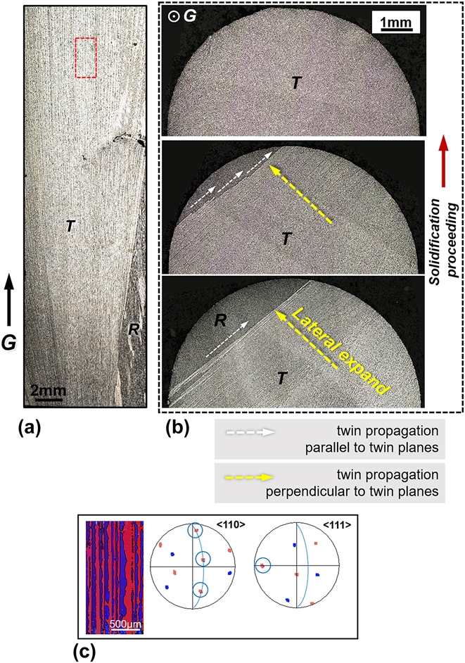
Figure 1 shows the typical competition behavior between twinned dendrites and columnar regular ones in the directionally solidified Al–4.5 wt% Cu alloy at a constant growth rate of 3000 μm/s. In Fig. 1(a) twinned dendrite grain labeled “T” appeared on the left bottom of the microstructure and then grew and expanded laterally from left to right, rapidly overgrowing the regular columnar grain labeled “R”. The growth advantage of twinned dendrites was apparent. It can also be noticed that there was a small and systematic misorientation between each twinned lamellae at the beginning. As solidification proceeded, twinned dendrite lamellae became nearly parallel with each other, with a growth direction almost parallel to G.
(a) Competitive growth between twinned dendrites (labeled “T”) and regular columnar ones (labeled “R”) in longitudinal microstructure at 3000 μm/s. (b) Evolution of transverse microstructures along G at 3000 μm/s. (c) Corresponding EBSD analyses of the twinned dendrites in the red rectangle region in (a). In 〈110〉 and 〈111〉 pole figures, the common directions are all circled. The middle arcs indicate the (111) twin planes.

The evolution of transverse microstructures is shown in Fig. 1(b). The white and yellow arrows indicate the twin propagation in the direction parallel to and perpendicular to twin planes, respectively. As can be seen, the gradual invasion of twinned dendrites over regular ones in Fig. 1(b) was in fact achieved by the twin propagation along these two directions. In the end, twinned dendrites occupied the entire solidified structures. Figure 1(c) gives corresponding EBSD analyses obtained from the red rectangle region in Fig. 1(a). The distribution of spots in pole figures presents a typical feature of twin relation. In 〈110〉 pole figure, three pairs of common 〈110〉 directions (circled) are located on a (111) coherent twin plane (indicated with a blue arc). The other noncommon directions have a symmetric relationship with respect to this twin plane. Also, a common 〈111〉 direction is circled near the outer border of 〈111〉 pole figure, which is the normal of the (111) twin plane.
2. Competitive growth at a low growth rate
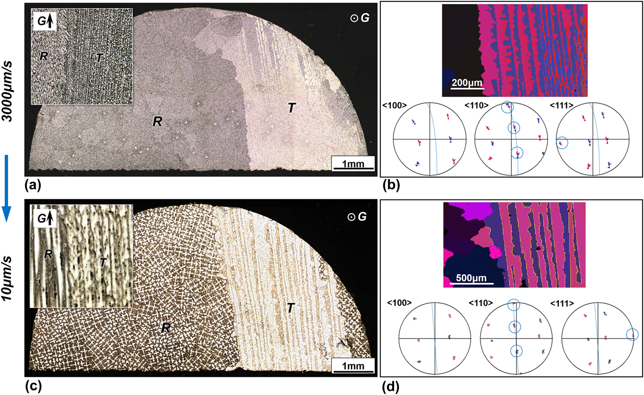
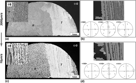
In Fig. 1, the twinned dendrites overgrew the regular columnar ones after a certain solidification distance at a high growth rate. To investigate the competitive growth between the twinned and regular columnar dendrites at a low growth rate, we carried out an abrupt reduction of the growth rate from 3000 to 10 μm/s during Bridgman solidification. Figure 2 shows the steady-state transverse microstructures at 3000 and 10 μm/s and corresponding EBSD analyses. In Fig. 2(a), at 3000 μm/s, the solidified structure containing coexisting twinned and regular columnar dendrites was obtained as stated in Sec. III.A.1. The inset image gives the local longitudinal microstructure. After the reduction in growth rate, as displayed in Fig. 2(c), although these two kinds of dendrite growth can be both maintained at a lower rate of 10 μm/s, the lateral twin extension, prevailing at a high rate (see Fig. 1), ceased at 10 μm/s. From 3000 to 10 μm/s [Figs. 2(a) and 2(c)], the respective regions covered by twinned and regular columnar dendrites remained almost unchanged. The low growth rate indeed restrained the twin propagation perpendicular to the twin plane. As a result, the growth advantage of twinned dendrites over regular ones lost its effectiveness. Moreover, in some partial region of Fig. 2(c), the propagation along the twin plane over regular columnar dendrites was found to continue at 10 μm/s.
(a) and (c) Transverse microstructures at 3000 μm/s and 10 μm/s. The insets give the local longitudinal structures. (b) and (d) Corresponding EBSD analyses of twinned dendrite growth in (a) and (c). In pole figures, the common directions are circled and the middle arcs represent the (111) twin planes.
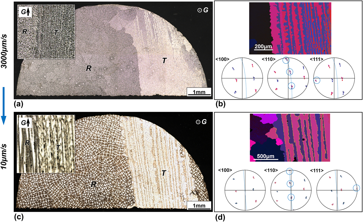
Generally, the regular columnar dendrites show a cruciform feature on the transverse sections, and the twinned dendrites appear as the special plate-like growth type. In the case of structural size aspect, both the twinned and regular columnar dendrites presented a coarsening trend after the growth rate reduction. A relevant increase in twin plane spacing was observed for the former and the primary arm spacing for the latter [see Figs. 2(a) and 2(c)]. Furthermore, as shown in 〈111〉 pole figure of Fig. 2(d), the twin planes at 10 μm/s are almost exactly perpendicular to the transverse section and parallel to G. The reduction in growth rate has prompted the adjustment of the twin plane growth to a direction more consistent with G during solidification.
3. Twin growth advantage with three essential components
The lateral twin extension perpendicular to twin plane was known to require the nucleation of a new stacking fault in tertiary branches issued from secondary arms.Reference Henry, Jarry and Rappaz8,Reference Salgado Ordorica9 At the same time, it has been evidenced that a larger undercooling was necessary for the formation of twins or stacking-faults during alloy solidification.Reference Han, Hirth and Embury21,Reference Hirth and Pond22 According to the classical model of regular dendrite growth kinetics,Reference Kurz, Giovanola and Trivedi23,Reference Kurz and Fisher24 a large growth rate during solidification usually corresponds to a large undercooling. In view of these, the cease of the lateral twin propagation shown in Fig. 2 can be attributed to the lacking undercooling caused by the reduction in growth rate (here 10 μm/s), which cannot meet the driving force need of the nucleation of new stacking faults. On the other hand, the in-plane twin propagation is relatively easy and could still proceed at a low growth rate, whose rate has been estimated as about one third of the growth rate along G during directional solidification.Reference Yang, Li, Chang, Zhong and Fu4
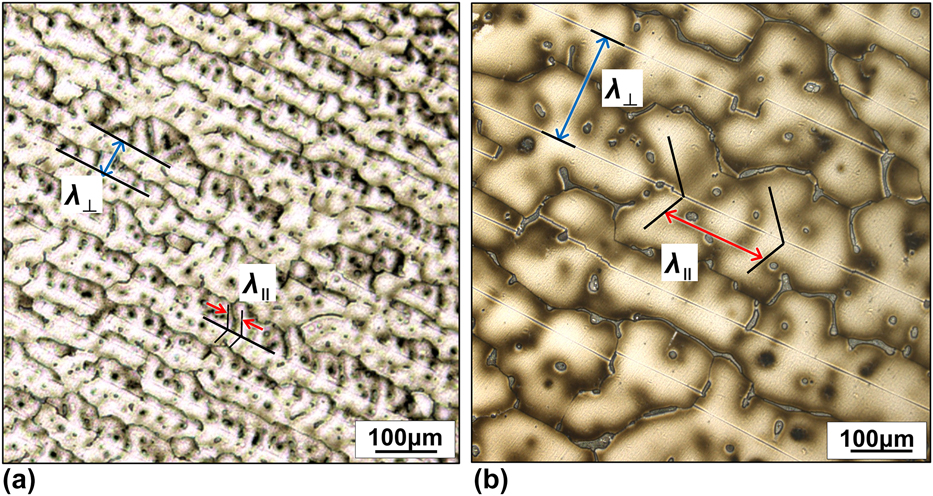
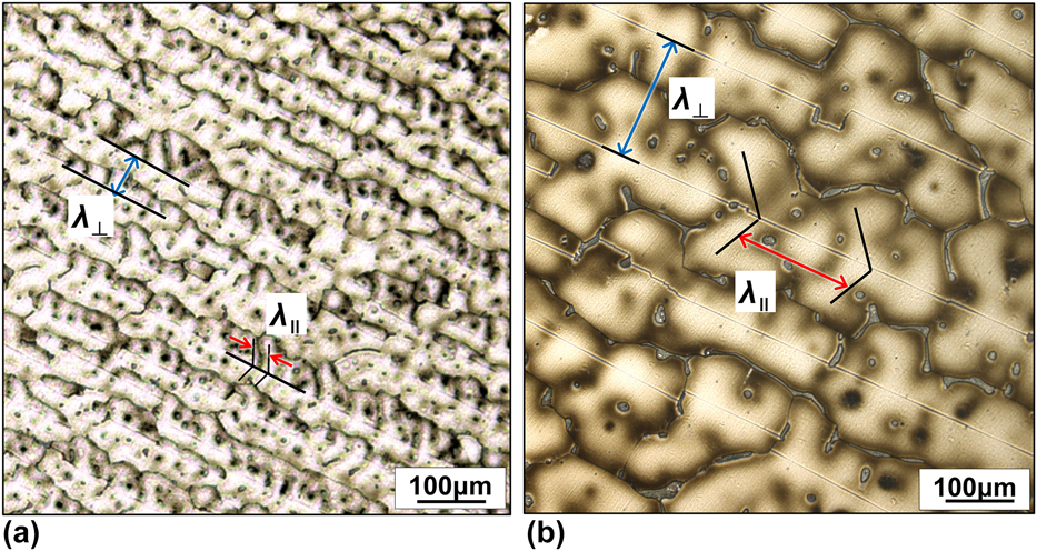
Figure 3(a) shows an enlarged view of the twinned dendrite microstructures at 3000 μm/s. As can be seen, the spacing between two successive twinned rows, λ⊥, was clearly larger than the dendrite trunk spacing within a row, λ∥. This is in line with previous experimental reportsReference Yang, Li, Chang, Zhong and Fu4,Reference Salgado Ordorica9,Reference Salgado-Ordorica, Valloton and Rappaz25 and suggests that the solute distribution field around the twinned dendrite tip is in fact asymmetrical. Comparing to the mutual solute transport between twinned dendrites belong to the same twin plane, more solute amount that rejected during growth was laterally transported in a direction perpendicular to the twin plane.Reference Salgado Ordorica9 In Fig. 3(b), for the twinned dendrite growth at 10 μm/s, λ∥ was observed to be almost equal to λ⊥. The solute distribution near the dendrite tip at a low growth rate tended to be more symmetrical. This can be another cause for the cease of the lateral twin extension perpendicular to twin plane at a low growth rate [Fig. 2(c)].
(a) and (b) Enlarged views of transverse microstructures at 3000 μm/s and 10 μm/s. λ⊥ is the spacing between two successive twinned rows and λ∥ is the dendrite trunk spacing within a row.
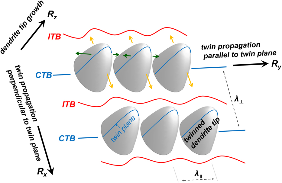
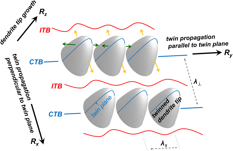
On the basis of above experimental findings, we believe that the growth advantage of twinned dendrites at the expense of regular columnar ones can be attributed to three essential contributions, as schematically shown in Fig. 4: the lateral twin propagation perpendicular to twin plane, R x, the twin propagation parallel to twin plane, R y, and the dendrite tip growth, R z. During the twinned dendrite growth, once the lateral twin propagation mechanism (R x) is launched at a certain position, the in-plane propagation (R y) will follow with ease, accompanying with dendrite tip growth (R z). A new row of twinned dendrites could then form efficiently.
Schematic illustration of the plate-like growth type of twinned dendrites. R x: the lateral twin propagation perpendicular to twin plane; R y: the twin propagation parallel to twin plane; R z: the dendrite tip growth. CTB indicates the coherent twin boundary and ITB indicates the incoherent twin boundary.
B. Estimation of the tip undercooling of twinned dendrite growth
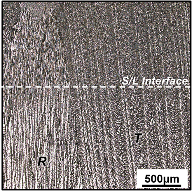
In Fig. 4, the dendrite tip growth component (R z) is directly related to the tip undercooling of twinned dendrites. As previously mentioned, the twinned dendrite tip undercooling is believed to be lower than that of regular columnar ones, which gives a kinetic advantage to twinned dendrite grains. Figure 5 gives the quenched interface of twinned and regular columnar dendrites directionally solidified at 3000 μm/s. Clearly, after quenching, the twinned dendrites could extend longer into the liquid phase.
Quenched microstructure of twinned and regular columnar dendrites directionally solidified at 3000 μm/s.

Nevertheless, it should be pointed out that the twinned dendrite tip was complex, and up to now, its real shape has not been clarified completely.Reference Salgado-Ordorica, Burdet, Cantoni and Rappaz14,Reference Salgado-Ordorica, Desbiolles and Rappaz15 Therefore, it is difficult to obtain an accurate result of the twinned dendrite tip undercooling. Even so, the twinned dendrite microstructures usually presented a plate-like or a lamellar growth morphology.Reference Salgado Ordorica9 From this point, we first estimate the tip undercooling of the plate-like morphology, based on the Kurz–Giovanola–Trivedi (KGT) model,Reference Kurz, Giovanola and Trivedi23 a generally accepted model for the regular columnar dendrite growth. During directional solidification, the dendrite tip undercooling mainly arises from three sources: the constitutional undercooling ΔT c, the curvature undercooling ΔT r, and the kinetics undercooling ΔT K, which is usually negligible.Reference Kurz, Giovanola and Trivedi23,Reference Kurz and Fisher24 The KGT model incorporates two undercoolings of ΔT c and ΔT r based on the marginal stability theoryReference Kurz, Giovanola and Trivedi23:
 $$\Delta T = \Delta {T_{\rm{c}}} + \Delta {T_{\rm{r}}}\quad ,$$
 $$\Delta {T_{\rm{c}}} = {m_{\rm{V}}}\left( {{C_0} - C_{\rm{L}}^*} \right)\quad ,$$
 $$\Delta {T_{\rm{r}}} = {{2\Gamma } / R}\quad ,$$
where m V is the growth rate dependent liquidus slope, C 0 is the initial solute concentration of experimental alloy,  $C_{\rm{L}}^*$ is the liquid composition at the dendrite tip, Γ is the Gibbs–Thomson parameter, and R is the dendrite tip radius growing at steady state:
 $${m_{\rm{V}}} = m\left[ {1 + {{{k_0} - {k_{\rm{V}}}\left( {1 - \ln \left( {{{{k_{\rm{V}}}} / {{k_0}}}} \right)} \right)} \over {1 - {k_0}}}} \right]\quad ,$$
 $$C_{\rm{L}}^{\rm{*}} = {{{C_0}} / {\left( {1 - \left( {1 - {k_{\rm{V}}}} \right){\rm{Iv}}\left( {{P_{\rm{c}}}} \right)} \right)}}\quad ,$$
 $$R = {\left[ {{{\left( {{\Gamma / {{\sigma ^*}}}} \right)} / {\left( {{m_{\rm{V}}}{\zeta _{\rm{c}}}{G_{\rm{c}}} - G} \right)}}} \right]^{{1 / 2}}}\quad ,$$
where m is the equilibrium liquidus slope, k 0 is the equilibrium partition coefficient, Iv is the Ivantsov function, and σ* is a stability constant (here given by 1/4π2). The parameter k V is the growth rate dependent partition coefficient, and according to the model formulated by Aziz,Reference Aziz26 it can be given by
 $${k_{\rm{V}}} = {{{k_0} + \left( {{a / D}} \right)V} \over {1 + \left( {{a / D}} \right)V}}\quad ,$$
where a is a characteristic length scale related to the interatomic distance and D is the liquid diffusion coefficient. The solutal Peclet number P c is defined as
 $${P_{\rm{c}}} = {{RV} / {2D}}\quad .$$
The Ivantsov function for a needle-like crystal corresponding to the paraboloid of revolution can be given byReference Kurz and Fisher24
 $${\rm{Iv}}\left( {{P_{\rm{c}}}} \right) = {P_{\rm{c}}}\exp \left( {{P_{\rm{c}}}} \right){E_1}\left( {{P_{\rm{c}}}} \right)\quad ,$$
where E 1 is the exponential integral function. ζc is a solutal stability parameter and G c is the solutal gradient at the interface:
 $${\zeta _{\rm{c}}} = {{1 - 2{k_{\rm{V}}}} / {\left( {{{\left[ {1 + {{\left( {{{2\pi } / {{P_{\rm{c}}}}}} \right)}^2}} \right]}^{{1 / 2}}} - 1 + 2{k_{\rm{V}}}} \right)}}\quad ,$$
 $${G_{\rm{c}}} = - \left( {1 - {k_{\rm{V}}}} \right){{VC_{\rm{L}}^{\rm{*}}} / D}\quad .$$
For the plate-like growth morphology, Eq. (9) should be modified asReference Kurz and Fisher24
 $${\rm{Iv'}}\left( {{P_{\rm{c}}}} \right) = {\left( {\pi {P_{\rm{c}}}} \right)^{1/2}}\exp \left( {{P_{\rm{c}}}} \right){\rm{erfc}}\left( {P_{\rm{c}}^{{{\rm{1}} / {\rm{2}}}}} \right)\quad ,$$
where erfc is the complementary error function. At the same time, the curvature undercooling ΔT r for the plate-like growth morphology can be given by
 $$\Delta {T_{{\rm{r,T}}}} = {\Gamma / R}\quad .$$
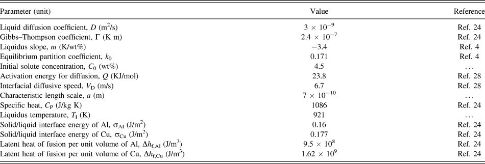
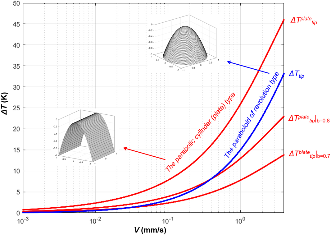
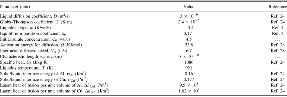
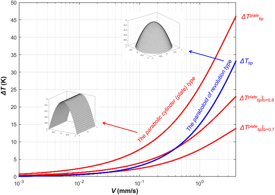
The thermophysical parameters of the alloy are listed in Table I. Figure 6 shows the calculation results of the tip undercooling of regular columnar growth, with a needle-like and a plate-like morphology, versus growth rate using the KGT model method. As can be seen, the tip undercooling of a plate-like morphology  $\Delta T_{{\rm{tip}}}^{{\rm{plate}}}$ (red curve) is always higher than that of a needle-like morphology ΔT tip (blue curve). This indicates that the plate-like tip would grow at a lower temperature than the needle-like tip during S/L interface advance, and the former seems to possess no kinetic growth advantage than the latter.
Thermophysical parameters of the Al–4.5 wt% Cu alloy used in calculation.
Plot of the calculated results of the tip undercooling of regular columnar growth, with a needle-like and a plate-like morphology, versus growth rate using the KGT model method.
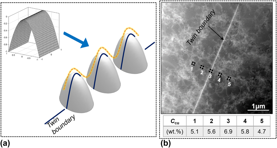
In fact, as shown in Fig. 7(a), the twinned dendrites within the same twin plane, which together form one “plate”, are independent of each other. As outlined by the yellow dashed curve, there exist several morphological ravines between the neighboring twinned dendrite tips that provide positions for the solute accumulation. Meanwhile, the solute enrichment phenomenon usually occurred near the twin boundary, as previously reported in the experimental results of the Al–30 wt% Zn alloys.Reference Salgado-Ordorica, Burdet, Cantoni and Rappaz14,Reference Salgado-Ordorica, Desbiolles and Rappaz15 As a result, this would consume a certain amount of solute elements and induce an associated decrease in the liquid concentration at the dendrite tip  $C_{\rm{L}}^*$. Figure 7(b) gives the transverse dark-field STEM (DF-STEM) micrograph taken across the twin boundary in Al–4.5 wt% Cu alloy directionally solidified at 3000 μm/s. A continuous linear region can be distinctly recognized by its higher brightness along the twin boundary. Several EDS measurements (indicated with the small crosses labeled 1–5) were performed, and the results are shown in the inset table. A solute enrichment can also be observed near the twin boundary region.
(a) Plot of the plate-like twinned dendrite growth and (b) the solute enrichment near the twin boundary in dark field scanning TEM view.
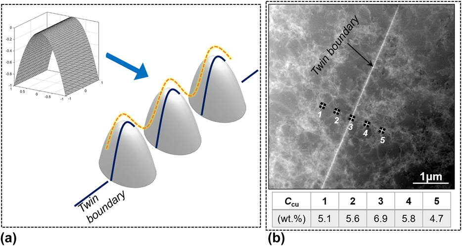
Note that it is very difficult to quantify the total solute enrichment near the twin boundary and also the liquid concentration at the dendrite tip, considering the complex twinned dendrite tip shape and the EDS measurement accuracy. Here we roughly estimated the liquid composition at the twinned dendrite tip by introducing a regulation factor b into Eq. (6) (0 < b < 1):
 $$C_{{\rm{L,T}}}^{\rm{*}} = {{b \cdot {C_0}} / {\left( {1 - \left( {1 - {k_{\rm{V}}}} \right){\rm{Iv'}}\left( {{P_{\rm{c}}}} \right)} \right)}}\quad .$$
As shown in Fig. 6, when b is equal to 0.8, the tip undercooling of plate-like morphology,  ${\left. {\Delta T_{{\rm{tip}}}^{{\rm{plate}}}} \right|_{b = 0.8}}$, has been less than needle-like morphology, ΔT tip, in the growth rate range larger than 1000 μm/s. Furthermore, when b is equal to 0.7,
 ${\left. {\Delta T_{{\rm{tip}}}^{{\rm{plate}}}} \right|_{b = 0.7}}$ has been less than ΔT tip in a larger rate range, and the plate-like tip morphology would take a kinetic growth advantage over the needle-like one. It can be speculated that the liquid concentration at the twinned dendrite tip should be close to the tip liquid composition of a plate-like morphology with b equal to 0.7–0.8. This provides a theoretical estimation of the solute concentration at the twinned dendrite tip during growth, despite the fact that the accurate concentration field can be known only after the tip morphology of twinned dendrites is quantified.
C. Competition among twinned dendrites in different feathery grains
1. Competitive growth between neighboring twinned dendrites
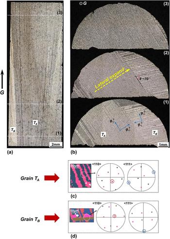
The competitive growth also took place between the neighboring twinned dendrites in different feathery grains at 3000 μm/s. Figure 8 shows the longitudinal and transverse microstructure evolution at 3000 μm/s and corresponding EBSD analyses. The white dotted lines (labeled 1, 2, and 3) in Fig. 8(a) indicate the cutting positions of transverse sections given in Fig. 8(b). As can be seen, in the bottom zone of Fig. 8(a), two sets of twin lamellae, feathery grains T A and T B, were present at the beginning. As solidification proceeded, the grain T A gradually suppressed the growth of grain T B. More distinct in Fig. 8(b), from sections (1) to (3), the twinned dendrites in T A laterally expanded and invaded the whole volume of the section in the end. As schematically indicated by blue arrows in Fig. 8(b-1), the competitive growth between grains T A and T B was actually realized by the competition between the twin propagation perpendicular to twin plane in T A, (R xA), and the twin propagation parallel to twin plane in T B, (R yB). The former process (R xA) kept down the latter one (R yB) and owned a higher growth efficiency during solidification.
Competitive growth between neighboring twinned dendrites of different feathery grains in longitudinal (a) and transverse (b) microstructures at 3000 μm/s. The white dotted lines [labeled 1, 2 and 3 in (a)] indicate the cutting positions of transverse sections in (b). (c) and (d) The respective EBSD analyses of grain T A and T B.
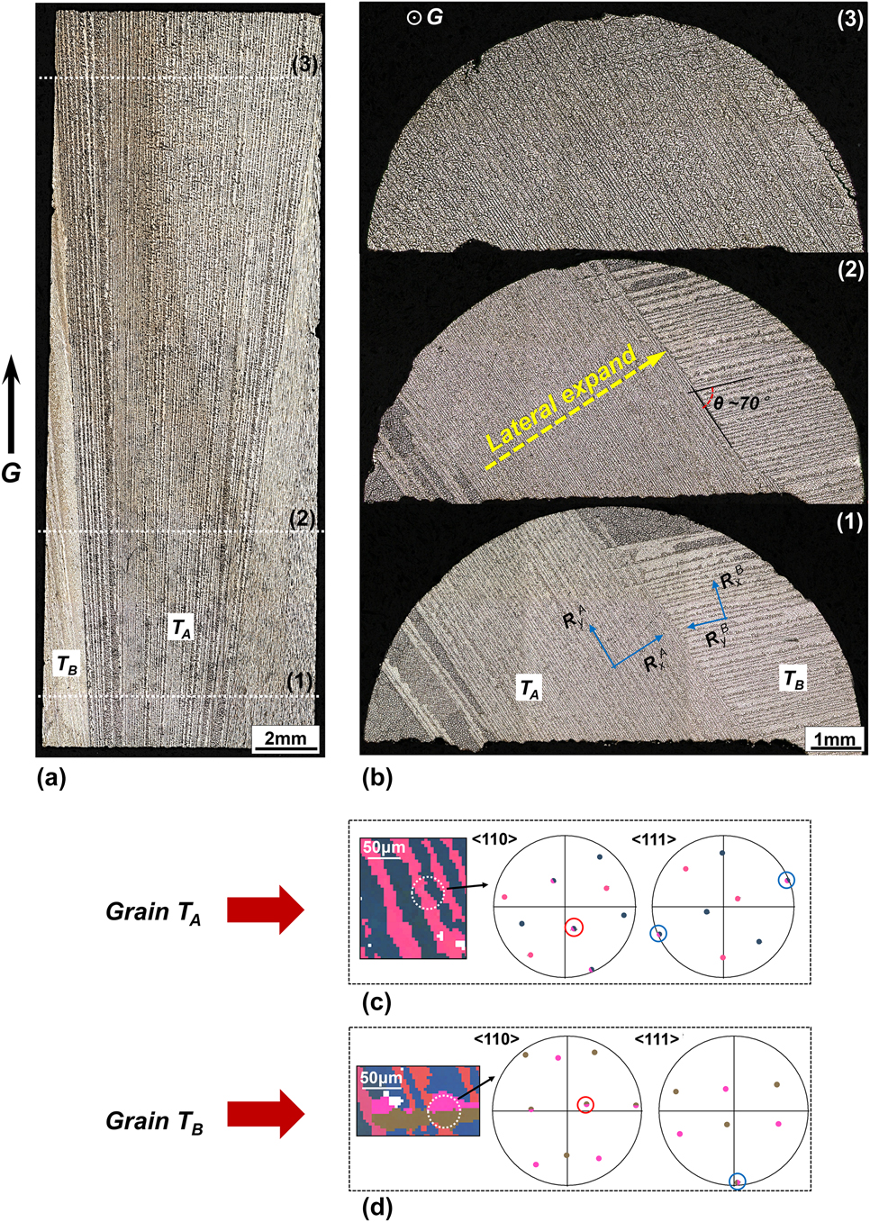
It is worth noting that, in the pole figures of grains T A and T B [Figs. 8(c) and 8(d)], the common 〈111〉 directions (circled in blue) are both located near the outer border, evidencing that their twin planes are both nearly parallel to G direction. At the same time, in the 〈110〉 pole figures, the growth direction of dendrite trunks (circled in red) in T A and T B both present a misorientation of about 20° with G. To sum up, no large orientation difference exists between the twinned dendrites in T A and T B. According to the classical Walton–Chalmers model, the twinned dendrite tip undercooling of these two grains T A and T B seems to be equivalent and no competitive growth should occur during the solidification process. This is obviously inconsistent with above experimental results. In addition to the influence of tip undercooling, it has been recently reported that the solute interaction also has a significant effect on the competitive growth mechanism of neighboring regular dendrites.Reference Zhou, Volek and Green19,Reference Li, Wang, Wang and Wang20,Reference Meng, Lu, Zhang, Li, Chen, Wang, Zhou, Jin, Sun and Hu27 The solute field overlap could inhibit the growth of regular dendrites during their mutual impingement near grain boundaries. Likewise, by analyzing the change of the local solute field of neighboring twinned dendrite tips, an attempt was made to explain the competitive growth behaviors in Fig. 8.
2. Two situations near the grain boundary between feathery grains
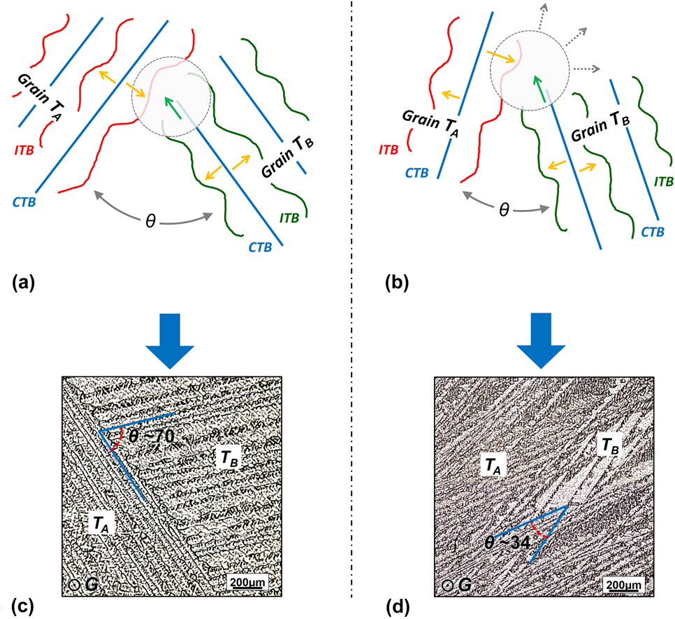
The mutual orientation, θ, between the twin planes of grains T A and T B is about 70° [see Fig. 8(b-2)]. With this relatively large orientation, grains T A and T B encountered near the grain boundary, and the former one suppressed the latter one during competitive growth. The sketch map of the impingement solute field near the grain boundary between these two feathery grains is plotted in Fig. 9(a). Figure 9(c) shows a partial enlarged view of microstructure in Fig. 8(b-2).
Schematic illustration of the competitive growth between twinned dendrites of two different feathery grains T A and T B: (a) The mutual orientation θ among the twin planes of T A and T B is relatively large; (b) θ is relatively small. (c) and (d) Competitive growth microstructures between grain T A and T B at 3000 μm/s corresponding to situations in (a) and (b), respectively.
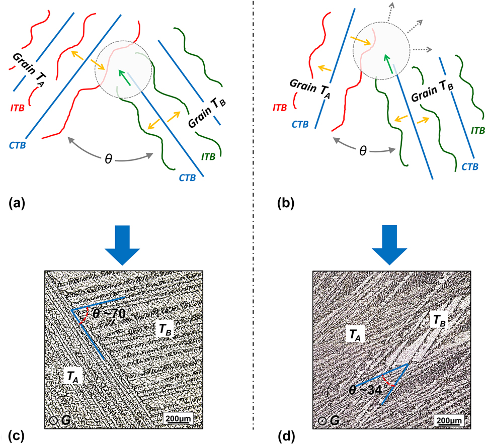
In Fig. 9(a), the yellow arrows represent the solute transport in the direction perpendicular to twin plane, toward the wavy incoherent boundary. The green arrows represent the mutual solute transport between twinned dendrite tips at the same twin plane. During competitive growth, concentration enrichment would occur in the local region near the grain boundary (symbolically, the gray region circled). Considering the asymmetry solute distribution around the twinned dendrite tip as stated, near the grain boundary, the solute transport perpendicular to the twin plane of grain T A (yellow arrow) was greater in amount and more efficient than the solute transport along twin plane of grain T B (green arrow). It is known that the driving force for dendrite growth decreases with the increasing liquid concentration.Reference Li, Wang, Wang and Wang20,Reference Kurz and Fisher24 Therefore, under above situation, lateral extension of grain T A, has an advantage over the in-plane extension of grain T B. Moreover, the spacing between two successive twinned rows, λ⊥, has been already known to be larger than the dendrite trunk spacing along twin plane, λ∥. This could provide more spacing for the lateral solute diffusion of grain T A and thus also contribute to its lateral growth.
Additionally, as displayed in Fig. 9(b), when the twin plane misorientation between two feathery grains T A and T B is relatively small, the upper right broad space (the circled gray region) appearing near grain boundary is highly beneficial for the solute transport outwards (along gray dotted arrows). In this case, twinned dendrites in grains T A and T B were provided equal chance to develop and their growth can coexist, as shown in Fig. 9(d).
IV. CONCLUSIONS
The competitive growth behaviors between twinned dendrites and regular columnar ones were investigated in detail at high and low growth rates during Bridgman solidification. The strong growth advantage of twinned dendrites was found to attribute to three essential contributions, i.e., the lateral twin propagation perpendicular to twin plane, the twin propagation parallel to twin plane, and the dendrite tip growth. Experimental results showed that a low growth rate (10 μm/s) definitely restrained the lateral twin propagation perpendicular to the twin plane. Subsequently, the growth advantage of twinned dendrites over regular ones was absent. Meanwhile, the twinned dendrite tip undercooling was roughly estimated based on the plate-like growth morphology using the KGT model method. Furthermore, the competitive growth among the twinned dendrites in different feathery grains was also observed at 3000 μm/s. When the mutual orientation between the twin planes of different grains was relatively large, the lateral twin propagation would keep down the in-plane twin propagation process and possess a higher growth efficiency. When the mutual orientation was relatively small, the twinned dendrites in neighboring grains could coexist.
ACKNOWLEDGMENTS
The authors are grateful for financial support from the Natural Science Foundation of China (No. 51474174) and the Foundation of State Key Lab of Solidification processing (101-QP-2014 and 133-QP-2015).