1. Introduction
The components of the manipulator are connected through revolute joints. The rational design of revolute joint tolerances is crucial for achieving system performance and assembly processes, inevitably leading to the presence of clearances within the revolute joints. Additionally, the working process of the manipulator can lead to wear and tear, resulting in an increase in the original clearance within the revolute joint. The clearance within revolute joints has a significant impact on the dynamic characteristics of the system. It can increase the tracking error of the end effector, worsen the impact and wear between components, and lead to a decrease in system accuracy. For example, in applications such as maintenance and assembly of robotic arms, it can seriously affect work quality and efficiency. Moreover, repeated impacts and stress concentrations caused by the clearance within the revolute joint can significantly accelerate fatigue damage, ultimately leading to premature failure of critical components. Therefore, based on the objective physical conditions (including clearance within revolute joints, friction, etc.), it is of great theoretical and engineering significance to conduct comprehensive and accurate kinematic and dynamic modeling and simulation research on the mechanical arm.
Due to the objective existence and harmfulness of clearance revolute joints, research on clearance revolute joints is particularly important. Xiang et al. [Reference Xiang, Yan, Wu and Niu1] investigated issues related to feedback control of mechanisms with clearance joints. Varedi-Koulaei et al. [Reference Varedi-Koulaei, Daniali and Farajtabar2] investigated the effects of revolute joint clearance and operating speed on the dynamic performance of a 3RRR (revolute-revolute-revolute) planar manipulator. Impact collision phenomena are often present in the interaction between components in physical systems, causing changes to the system’s original motion state and having significant effects. The mechanical essence of this can be attributed to a highly nonlinear dynamic response process with non-stationary and variable boundary characteristics. The effective construction of a universally applicable continuous impact contact force model is crucial for studying such nonlinear dynamic problems, and in recent years, it has also attracted a large number of scholars to engage in related research [Reference Zhang, Li, Shi, Wang, Zhang, Zhang and Wu3–Reference Zhu, Song, Bonaiti and Gorla7]. Building on the consideration of revolute joints with clearance, compared to the nonsmooth approach [Reference Brogliato8] for modeling contact objects, Corral et al. [Reference Corral, Moreno, García and Castejón9, Reference Corral, Gismeros Moreno, Meneses, García and Castejón10] defined and discussed several penalty contact models and described the computational algorithms between two contact bodies. Jia et al. [Reference Jia and Chen11] combined the theory of elasticity, finite element method, and least squares method to accurately predict the nonlinear dynamic behavior of parallel robots, establishing a conformal contact force model for spherical joint clearances and validating it through ABAQUS simulations. Chaturvedi et al. [Reference Chaturvedi, Sandu and Sandu12] provided a detailed definition of spatial prismatic joints with clearances and a general nonlinear programming problem formulation for the multibody dynamics of systems discretely incorporating these clearance-prone basic joints.
Based on the consideration of the impact of clearances on the dynamics and reliability models, researchers have looked into the influence of different factors on the performance of mechanisms. Sheng et al. [Reference Sheng and Chen13] proposed a general method for dynamic modeling and analysis applied to the spatial parallel coordinate measuring mechanism (SPCMM). A dynamic modeling and analysis method considering three spherical clearance joints based on Lagrange multiplier technology has been developed, and the position motion model of the joint elements and contact force models has been established. Jiang et al. [Reference Jiang, Lin, Zhou, Wang, Li, Xiao and Fuqiang14] established an exact dynamic model and dynamic accuracy reliability model for a six-bar mechanism considering irregular wear clearances, and analyzed the effects of clearance values and traveling speed on wear characteristics and dynamic response. Chen et al. [Reference Chen and Gao15] took a two-degree-of-freedom seven-bar mechanism as an example, derived its dynamic model, and established a dynamic accuracy reliability model based on stress-strength interference theory, studying the effects of driving speed, clearance values, and friction coefficient on the mechanism’s dynamic accuracy. Furthermore, researchers have also investigated the dynamic behavior of clearance structures of various configurations. Chen et al. [Reference Chen and Yang16] proposed a modeling method for a 3-RRRRR (revolute-revolute-revolute-revolute-revolute) mechanism with clearances, and analyzed the dynamic response with and without axial clearances using the Runge-Kutta method. Cretescu et al. [Reference Cretescu, Neagoe and Saulescu17] studied the dynamic behavior of a Delta robot, considering clearances in spherical joints, friction, and flexibility of link units. Chen et al. [Reference Chen and Gao18] studied the dynamic response and dynamic accuracy reliability of planar mechanisms with multiple lubrication clearances. Tian et al. [Reference Tian, Xiao, Sun, Hu, Liu and Flores19] studied the dynamic coupling problem of a gear transmission multi-body system with rotational joints with clearances using a comprehensive numerical method.
Compared to the contact dynamics modeling of multi-body systems [Reference Yang, Li, Yin, Gong, Chen and Zhou20, Reference da Silva, Coelho, Gonçalves, Novais and Flores21], friction and collision between mechanisms are also important challenges. Chen et al. [Reference Chen, Feng, Peng, Sun, He and Yu22] established a dynamic model of a planar multi-body system with joint clearances, describing the contact-impact phenomenon between the pin and hole based on the continuous contact law and contact force model, and considering the influence of friction on the rotational joint clearances through a modified friction force model. Song et al. [Reference Song, Peng and Kan23] proposed a non-smooth numerical calculation method suitable for different types of joint clearances, and combined Newton’s collision law to handle contact reactions. Alves et al. [Reference Alves, Peixinho, da Silva, Flores and Lankarani24] studied the constitutive relationship of solid contact collisions and compared viscoelastic contact force models. Safaeifar et al. [Reference Safaeifar and Farshidianfar25] derived explicit expressions for the hysteresis damping coefficient and restitution coefficient. Zhou et al. [Reference Zhou, Huang, Xian, Zhou, Deng and Zhou26] explored the evolution of friction characteristics from cold start to thermal equilibrium through a series of steady-state friction experiments. Varedi et al. [Reference Varedi, Daniali, Dardel and Fathi27] reduced the impact of joint clearances on system impacts through optimization algorithms. Li-Xin et al. [Reference Li-Xin and Yong-Gang28] studied the dynamic performance of a 2-degree-of-freedom parallel manipulator based on Hertz’s contact law and Coulomb’s friction law. The contact force law, based on Hertz contact theory, is a regularization of the contact force problem [Reference Machado, Moreira, Flores and Lankarani29, Reference Johnson30]. Jiang et al. [Reference Jiang and Chen31] analyzed the influence of the LuGre model and the improved Coulomb friction model on the dynamic response of mechanisms with clearances. In addition, based on dynamic modeling and parameter optimization of the contact model, some scholars have also discussed the trajectory planning problem with revolute joints containing clearances [Reference Sincar and Bayraktaroglu32–Reference Wang and Wang36]. Farajtabar et al. [Reference Farajtabar, Daniali and Varedi37] focused on enhancing the system’s positioning accuracy by analyzing the trajectory planning of a 3-RRR (revolute-revolute-revolute) parallel manipulator with clearance joints.
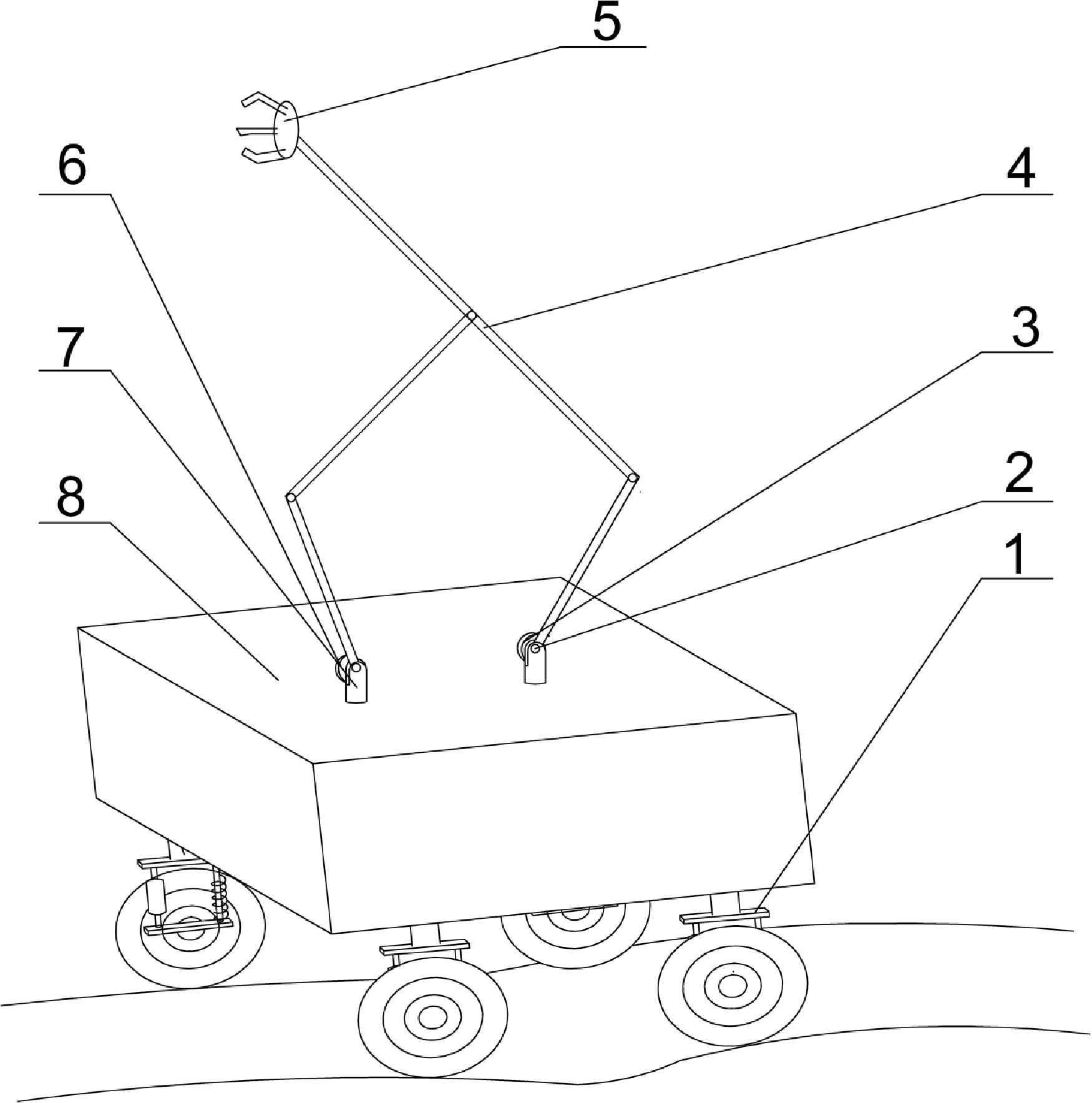
The mobile parallel manipulator. (1) Spring damping suspension; (2) Drive joint 1; (3) Drive motor 1; (4) Parallel robotic arm; (5) Load; (6) Drive motor 2; (7) Drive joint 3; (8) Mobile platform.

Although extensive research has been conducted on analyzing the impact of clearances on the performance of mechanisms, and various modeling and optimization methods have been proposed, several challenges persist:
-
1. The research is highly targeted but lacks generality: Current studies mostly focus on specific types of machines, lacking universal dynamic models that can be applied to different types of machines.
-
2. The nonlinear complexity of revolute joints: Current studies predominantly employ Hertzian contact theory, the Coulomb friction law, or elastic theory for modeling, yet the applicability of these methods in high-dynamic environments still requires further validation.
-
3. The issue of integrity in dynamic models: Most studies focus solely on trajectory planning or specific dynamic characteristics, neglecting the impact of inter-joint support reaction forces on the system. They fail to simultaneously consider the combined effects of impact forces, contact forces, and friction forces, limiting the reliability of the model in practical applications.
Future research necessitates further development of modeling approaches based on general contact mechanics theory, integrating intelligent optimization algorithms to enhance the predictive accuracy of the dynamic performance of clearance mechanisms. Simultaneously, standardized modeling methods should be explored for different types of clearance mechanisms to improve the generalizability and engineering applicability of studies.
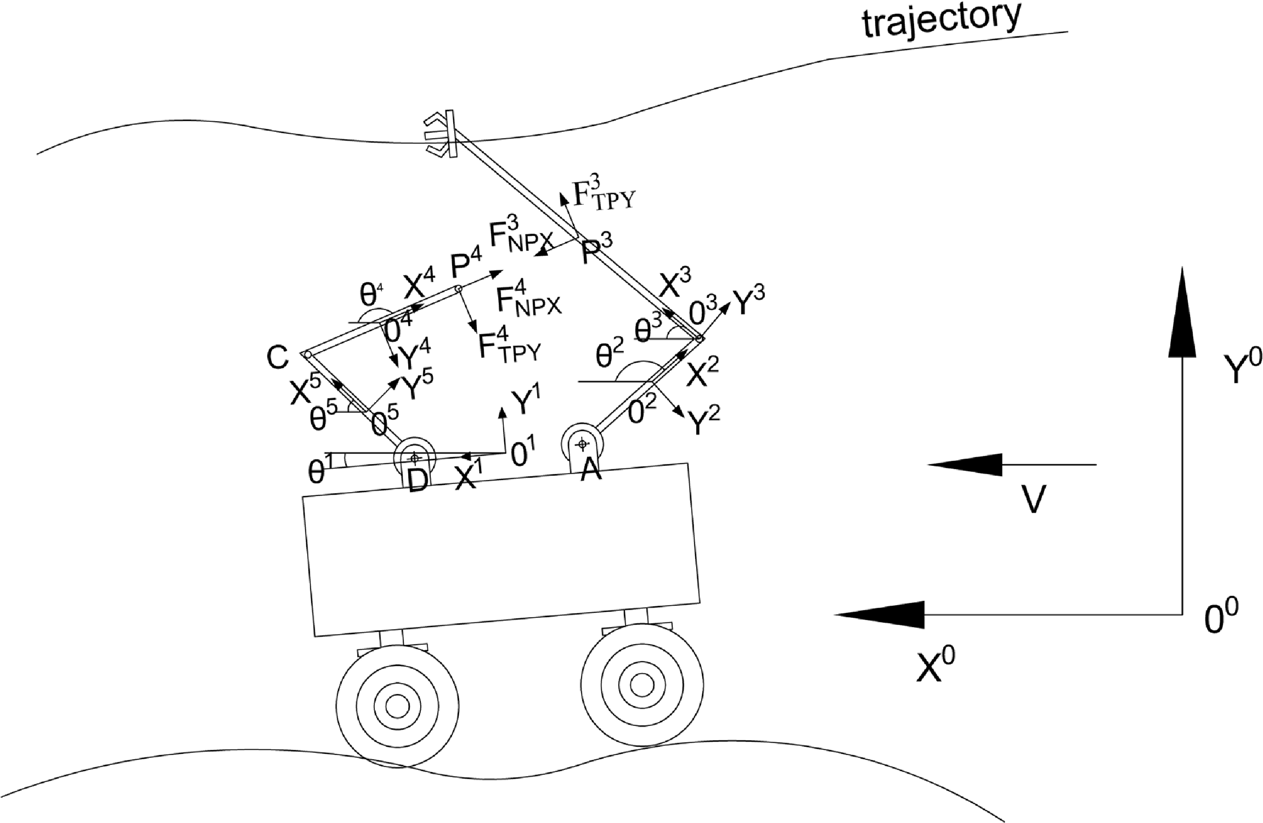
Diagram of a mobile parallel manipulator.

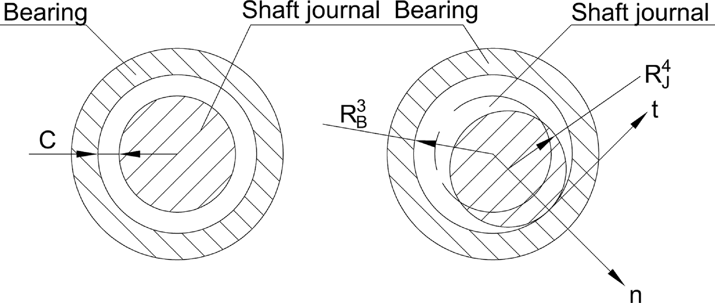
The revolute joint with clearances.

This paper is based on the theory of multi-body dynamics [Reference Yang, Li, Yin, Gong, Chen and Zhou20, Reference Shabana38], focusing on the completeness, accuracy, universality, and systematicity of system dynamics modeling. Taking a mobile parallel manipulator with clearances and frictional revolute joints [Reference Li, Huang, Hu, Zhang and Shi39] (Fig. 1) as the research object, the revolute joints with clearances in the parallel system are opened (Fig. 2). The joint support reaction forces, collision impact forces, and friction forces are used to replace the constraints of the revolute joints and are applied to the system, thus forming a mobile double serial manipulator system. The study investigates the impact of various parameters and loads on the impact and friction forces within the clearance of a revolute joint, discussing the engineering significance of comprehensive dynamic modeling of clearance revolute joints. The subsequent content is arranged as follows. In Section 2, the kinematic analysis of a mobile parallel manipulator with a clearance revolute joint is introduced. This section introduces a collision impact direction matrix and obtains the position, velocity, and acceleration of the collision contact points of the clearance revolute joint. In Section 3, dynamic analysis of a mobile parallel manipulator and a mobile double serial manipulator is conducted. It also includes an analysis of the collision impact force model and the LuGre friction force model, and considers the joint reaction forces of the clearance revolute joint. Section 4 analyzes the numerical simulation results. Section 5 provides the conclusion.
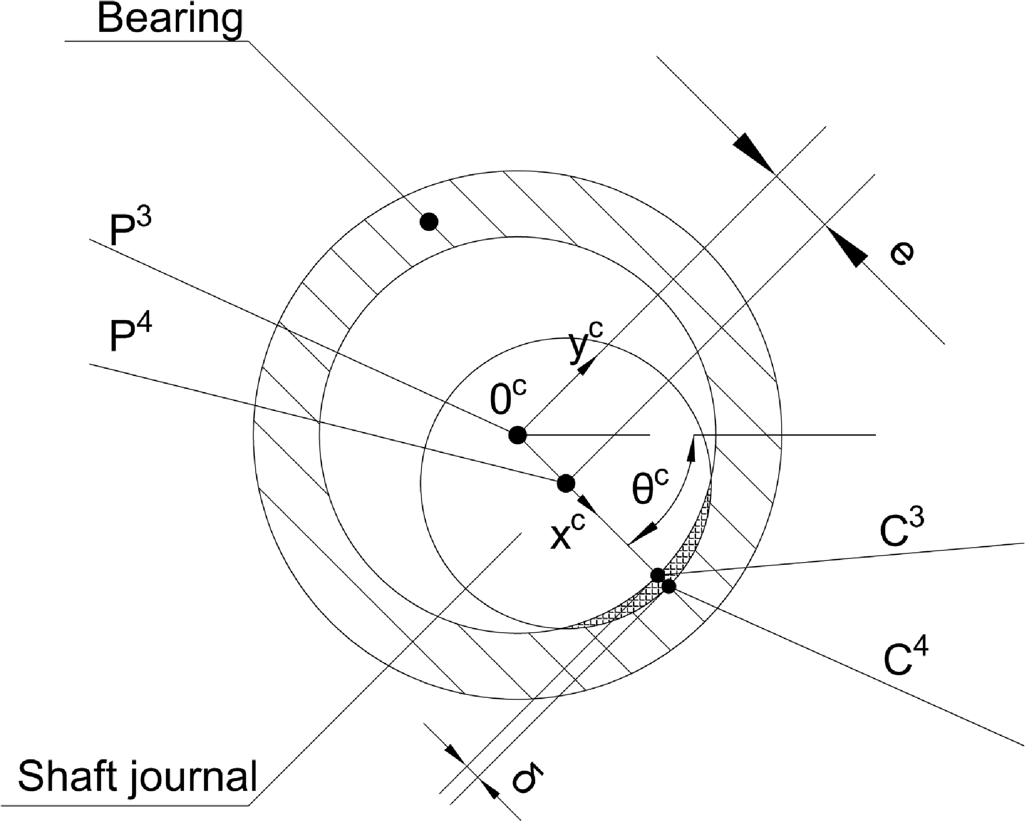
Collision push into depth.

2. Systematic kinematic modeling takes into account clearance and friction in revolute joints
When a manipulator is performing a predetermined task, such as trajectory tracking, the revolute joints with clearances will generate impact collisions and friction between the shaft journal and bearing. This results in collision impact forces and friction forces that seriously affect the system’s dynamic performance. There are three motion conditions of the revolute joint shaft journal within the bearing when the manipulator is performing tasks [Reference Sun, Chen, Shi, Wang and Sun40]: (1) No-contact motion, as shown in Fig. 3; (2) Continuous contact motion with the revolute joint bearing, as shown in Fig. 3; (3) Impact collision motion with the revolute joint bearing, as shown in Fig. 4. In actual working conditions, these three types of motion alternate back and forth. It is quite challenging to accurately determine the shaft journal and the impact collision time between bearings in numerical analysis [Reference Muvengei, Kihiu and Ikua41, Reference Muvengei, Kihiu and Ikua42]. For specific collisions, relevant experimental data are needed to determine the collision time. Considering the generality of kinematic and dynamic modeling methods, this paper uses the Cartesian coordinate method to describe the kinematic and dynamic models of the system. Figures 1 and 2 show schematic diagrams of a mobile manipulator. Figure 1 shows a mobile parallel manipulator opening at a revolute joint with clearance and applying corresponding joint support reaction forces, collision impact forces, and friction forces, evolving into the mobile double serial manipulator shown in Fig. 2. In Fig. 2, O 0-X 0 Y 0 is the global coordinate system of the mobile double serial manipulator, and O i -X i Y i is the body coordinate system [Reference Yuwei, Minglu, Xinhua, Guangzhu and Bin43–Reference Yuwei, Shujin and Bin45] of component i (i = 1, 2, · · ·, 5). The position vector r i of any point on component i can be described as [Reference Yuwei, Minglu, Xinhua, Guangzhu and Bin43, Reference Yuwei, Xinhua, Qiyuan, Jiageng and Bin44]:
 \begin{equation} \mathbf{r}^{i}=\mathbf{R}^{i}+\mathbf{A}^{i}\overline{\mathbf{u}}^{i} \end{equation}
 $\mathbf{R}^{i}$
is the position vector of the origin of the body coordinate system of component i in the global coordinate system. A
i
is the transformation matrix.
 $\overline{\mathbf{u}}^{i}$
is the position vector of a point on component i in the body coordinate system.
Due to space limitations, only the connection between components 3 and 4 through a revolute joint with clearance will be considered. The position vector of the center point p
3 of the bearing of component 3 in the revolute joint is denoted as
 $\mathbf{r}_{p}^{\mathrm{3}}$
(measured in the global coordinate system). It can be expressed as:
 \begin{equation} \mathbf{r}_{p}^{\mathrm{3}}=\mathbf{R}^{\mathrm{3}}+\mathbf{A}^{\mathrm{3}}\overline{\mathbf{u}}_{p}^{\mathrm{3}} \end{equation}
In the revolute joint, the position vector of the center point p
4 of the shaft journal of component 4 is denoted as
 $\mathbf{r}_{p}^{\mathrm{4}}$
. It can be expressed as:
 \begin{equation} \mathbf{r}_{p}^{\mathrm{4}}=\mathbf{R}^{\mathrm{4}}+\mathbf{A}^{\mathrm{4}}\overline{\mathbf{u}}_{p}^{4} \end{equation}
Where
 $\overline{\mathbf{u}}_{p}^{\mathrm{3}}$
and
 $\overline{\mathbf{u}}_{p}^{\mathrm{4}}$
are position vectors of points p
3 and p
4, measured in the body coordinate system O
i
-X
i
Y
i
, as shown in Figs. 2 and 4.
As shown in Fig. 4, the eccentricity vector of the clearance revolute joint can be expressed as follows [Reference Muvengei, Kihiu and Ikua41]:
 \begin{equation} \mathbf{e}^{\mathrm{43}}=\mathbf{r}_{p}^{\mathrm{4}}-\mathbf{r}_{p}^{\mathrm{3}} \end{equation}
The
 $\mathbf{r}_{p}^{\mathrm{3}}$
and
 $\mathbf{r}_{p}^{\mathrm{4}}$
are defined in Eqs. (2) and (3).
Its eccentricity is expressed as:
 \begin{equation} e=\left\| \mathbf{e}^{\mathrm{43}}\right\| \end{equation}
Due to the
 $\mathbf{e}^{\mathrm{43}}=[e_{x}^{\mathrm{43}}\; \; \; e_{y}^{\mathrm{43}}]_{1\times 2}^{\mathrm{T}}$
(
 $e_{x}^{\mathrm{43}}$
and
 $e_{y}^{\mathrm{43}}$
are respectively the x and y components of
 $\mathbf{e}^{\mathrm{43}}$
in the global coordinate system), the direction angle θ
c
of the coordinate system O
C
-X
C
Y
C
relative to the global coordinate system can be obtained from Fig. 4.
 \begin{equation} \theta_{c}=a\tan 2\left(e_{y}^{\mathrm{43}},e_{x}^{\mathrm{43}}\right) \end{equation}
The transformation matrix, A c , of O C -X C Y C relative to the global coordinate system can be expressed as [Reference Shabana38]:
 \begin{equation} \mathbf{A}_c=\left(\begin{array}{l@{\quad}l} \cos \theta_c & -\sin \theta_c\\ \sin \theta_c & \cos \theta_c \end{array}\right) \end{equation}
The collision impact direction matrices of components 3 and 4 can be represented as follows:
 \begin{equation} \mathbf{A}_{c}^{\mathrm{3}}=\mathbf{A}_{c} \end{equation}
 \begin{equation} \mathbf{A}_{c}^{4}=\mathbf{A}_{c} \end{equation}
As shown in Fig. 4, the depth of penetration of the collision between the revolute joint shaft journal and the bearing is represented as follows [Reference Muvengei, Kihiu and Ikua41]:
 \begin{equation} \delta =e-c \end{equation}
Where c is the clearance amount of the revolute joint, this parameter is determined by the system in conjunction with tolerances, as shown in Fig. 4. Considering the collision penetration depth of the revolute joint, C 3 and C 4 are the contact points of the bearing and shaft journal collision, as shown in Fig. 4. By Eqs. (1)–(3), the position vectors of the contact points C 3 on the revolute joint bearing and C 4 on the shaft journal can be expressed as:
 \begin{equation} \mathbf{r}_{c}^{3}=\mathbf{R}^{3}+\mathbf{A}^{3}\overline{\mathbf{u}}_{p}^{3}+\mathbf{A}_{c}^{3}\overline{\mathbf{u}}_{c}^{3} \end{equation}
 \begin{equation} \mathbf{r}_{c}^{4}=\mathbf{R}^{4}+\mathbf{A}^{4}\overline{\mathbf{u}}_{p}^{4}+\mathbf{A}_{c}^{4}\overline{\mathbf{u}}_{c}^{4} \end{equation}
Where
 $\overline{\mathbf{u}}_{c}^{3}=[R_{B}^{3}\; \; \; 0]_{1\times 2}^{\mathrm{T}} , \overline{\mathbf{u}}_{c}^{4}=[R_{J}^{4}\; \; \; 0]_{1\times 2}^{\mathrm{T}} , R_{B}^{3}$
is the radius of the revolute joint bearing, and
 $R_{J}^{4}$
is the radius of the shaft journal, as shown in Figs. 3 and 4.
 $\overline{\mathbf{u}}_{c}^{3}$
and
 $\overline{\mathbf{u}}_{c}^{4}$
represent the body coordinates of the contact points of the bearing collision and the shaft journal collision in the O
C
-X
C
Y
C
coordinate system. The equations (11) and (12) are differentiated with respect to time to obtain the velocity of the contact point in the revolute joint, as follows [Reference Yuwei, Minglu, Xinhua, Guangzhu and Bin43, Reference Yuwei, Xinhua, Qiyuan, Jiageng and Bin44]:
 \begin{equation} \dot{\mathbf{r}}_{c}^{3}=\dot{\mathbf{R}}^{3}+\mathbf{A}_{\theta ^{3}}^{3}\overline{\mathbf{u}}_{p}^{3}\dot{\theta }^{3}+\mathbf{A}_{\theta _{c}}^{3}\overline{\mathbf{u}}_{c}^{3}\dot{\theta }_{c} \end{equation}
 \begin{equation} \dot{\mathbf{r}}_{c}^{4}=\dot{\mathbf{R}}^{4}+\mathbf{A}_{\theta ^{4}}^{4}\overline{\mathbf{u}}_{p}^{4}\dot{\theta }^{4}+\mathbf{A}_{\theta _{c}}^{4}\overline{\mathbf{u}}_{c}^{4}\dot{\theta }_{c} \end{equation}
 $\mathbf{A}_{\theta ^{i}}^{i}$
(i = 3, 4) represents the derivative of
 $\mathbf{A}^{i}$
with respect to
 $\theta ^{i}$
.
The relative velocity of the contact point of the revolute joint can be expressed by the following equation, as derived from Eqs. (13) and (14) [Reference Muvengei, Kihiu and Ikua41]:
 \begin{equation} \mathbf{v}_{c}^{43}=\dot{\mathbf{r}}_{c}^{4}-\dot{\mathbf{r}}_{c}^{3} \end{equation}
By combining Eqs. (7) and (15), we obtain:
 \begin{equation} \overline{\mathbf{v}}_{c}^{43}=\left(\mathbf{A}_{c}\right)^{\mathrm{T}}\mathbf{v}_{c}^{43}=\left[v_{n}\; \; \; v_{t}\right]_{1\times 2}^{\mathrm{T}} \end{equation}
 $v_{n}$
and
 $v_{t}$
are respectively the x and y components of the relative velocity
 $\mathbf{v}_{c}^{43}$
at the point of contact in the O
C
-X
C
Y
C
coordinate system.
The n and t directions are the normal and tangential directions of the collision of the revolute joint components, as shown in Fig. 3. The constraints of the moving double serial manipulator include holonomic and non-holonomic constraints [Reference Yuwei, Xinhua, Qiyuan, Jiageng and Bin44]. The end-point trajectory constraint equation (Fig. 2) can be expressed as:
 \begin{equation} \left\{\begin{array}{l} \mathbf{R}^{\mathrm{3}}+\mathbf{A}^{\mathrm{3}}\mathbf{U}_{P}^{\mathrm{3}}-\left[\begin{array}{l} r_{px}\\[9pt] r_{py} \end{array}\right]=\mathbf{0}_{\mathrm{2}\times \mathrm{1}}\\[9pt] r_{px}=v_{1x}\cdot t\cdot \cos \left(\dfrac{\mathrm{5{\unicode[Arial]{x03C0}} }}{\mathrm{180}}\right)+a_{\mathrm{0}}\\[9pt] r_{py}=v_{\mathrm{1}y}\cdot t\cdot \sin \left(\dfrac{\mathrm{5{\unicode[Arial]{x03C0}} }}{\mathrm{180}}\right)+b_{\mathrm{0}}\\[9pt] v_{1y}=k_{v2}\cdot v\cdot \sin \left(w_{a1}\cdot t\right)\\[5pt] v_{1x}=k_{v1}\cdot v\\[5pt] w_{a1}=\dfrac{\mathrm{2{\unicode[Arial]{x03C0}} }}{T_{v1}} \end{array}\right. \end{equation}
Here,
 $r_{px}$
and
 $r_{py}$
represent the x and y components of the end-effector trajectory in the global coordinate system.
The k
v1 and k
v2 parameters are trajectory velocity parameters that determine the impact of revolute joints with clearance on system dynamics performance by adjusting these parameters. The v is the horizontal speed of the moving carrier, T
v1 is the trajectory period parameter, and a
0 and b
0 are trajectory constants. The inverse kinematic constraint equation for a mobile parallel manipulator [Reference Yuwei, Minglu, Xinhua, Guangzhu and Bin43, Reference Yuwei, Xinhua, Qiyuan, Jiageng and Bin44] is C
1=0
13 × 1 (including Eq. (17)), and the forward kinematic constraint equation for a mobile double serial manipulator is C
2=0
9 × 1. In this context,
 $\mathbf{C}^{ij}\mathbf{(}\mathbf{q}^{i}\mathbf{,}\mathbf{q}^{j}\mathbf{)}$
represents the constraint relationship between components i and j [Reference Shabana38].
 \begin{equation} \left[\begin{array}{l} \mathbf{C}^{\mathrm{51}}(\mathbf{q}^{\mathrm{1}}\mathbf{,}\mathbf{q}^{\mathrm{5}})\\ \mathbf{C}^{\mathrm{45}}(\mathbf{q}^{\mathrm{4}}\mathbf{,}\mathbf{q}^{\mathrm{5}})\\ \mathbf{C}^{\mathrm{32}}(\mathbf{q}^{\mathrm{2}}\mathbf{,}\mathbf{q}^{\mathrm{3}})\\ \mathbf{C}^{\mathrm{21}}(\mathbf{q}^{\mathrm{1}}\mathbf{,}\mathbf{q}^{\mathrm{2}})\\ \mathbf{C}^{\mathrm{1}}(\mathbf{q}^{\mathrm{1}}\mathbf{,}t) \end{array}\right]=\mathbf{0}_{9\times 1} \end{equation}
The variable
 $\mathbf{q}^{i}=[\mathbf{R}^{i\mathrm{T}}\; \; \; \theta ^{i}]_{1\times 3}^{\mathrm{T}}$
(i = 1, 2, …, 5) in the equation is used to describe the configuration of component i. Using the independent coordinate method, the independent variables
 $\mathbf{q}_{i}^{1}$
for the inverse kinematics of the moving parallel manipulator can be obtained. The independent variables
 $\mathbf{q}_{i}^{2}$
for the forward kinematics of the moving double serial manipulator can also be obtained [Reference Yuwei, Shujin and Bin45]. The
 $\mathbf{q}_{i}^{1}$
and
 $\mathbf{q}_{i}^{2}$
are defined as follows:
 \begin{equation} \mathbf{q}_{i}^{\mathrm{1}}=\left[\theta ^{2}\; \; \; \left.\theta ^{5}\right]\right._{1\times 2}^{\mathrm{T}} \end{equation}
 \begin{equation} \mathbf{q}_{i}^{\mathrm{2}}=\left[\begin{array}{c@{\quad}c@{\quad}c@{\quad}c@{\quad}c@{\quad}c} r_{2}^{1} & \theta ^{1} & \theta ^{2} & \theta ^{3} & \theta ^{4} & \theta ^{5} \end{array}\right]_{1\times 6}^{\mathrm{T}} \end{equation}
The
 $\mathbf{q}_{i}^{1}$
and
 $\mathbf{q}_{i}^{2}$
can be used to describe the kinematic system configuration of the same mobile manipulator (as shown in Fig. 1). The kinematic configuration
 $\mathbf{q}$
of the system can be represented as [Reference Yuwei, Shujin and Bin45]:
 \begin{equation} \mathbf{q}=f^{1}\left(\mathbf{q}_{i}^{1},t\right) \end{equation}
 \begin{equation} \mathbf{q}=f^{2}\left(\mathbf{q}_{i}^{2},t\right) \end{equation}
In the equation,
 $\mathbf{q}=[\mathbf{q}^{1\mathrm{T}}\cdots \mathbf{q}^{5\mathrm{T}}]_{\mathrm{1}\times \mathrm{15}}^{\mathrm{T}}$
.
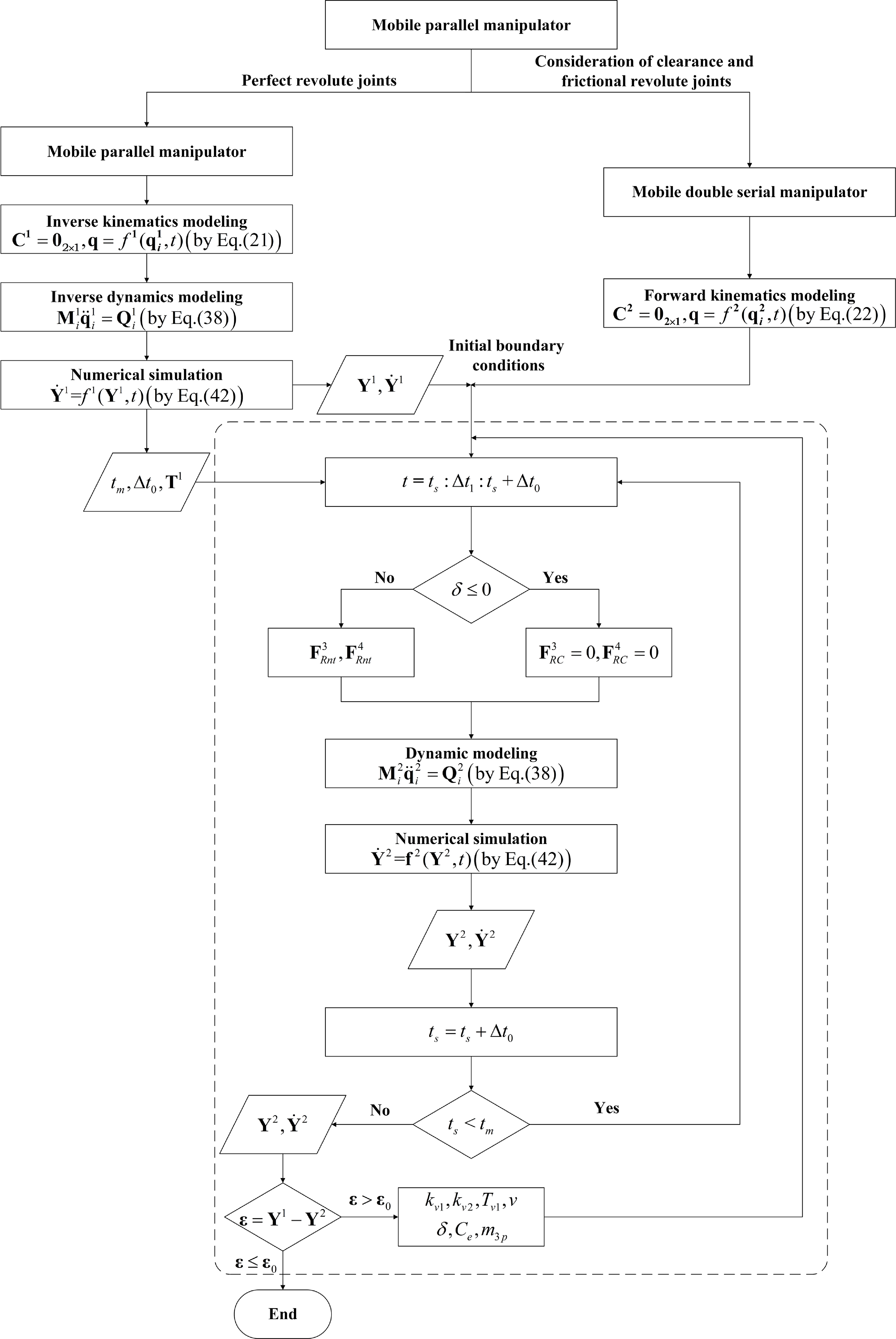
Numerical simulation flowchart.

3. Consideration of revolute joint clearances and friction in system dynamics modeling
Taking into account the energy loss in the collision process, the impact force of the collision [Reference Farajtabar, Daniali and Varedi37, Reference Yuwei, Shujin and Bin45] can be described as follows:
 \begin{equation} F_{n}=K\delta ^{n}+Dv_{n} \end{equation}
 \begin{equation} D=\left[\frac{3K\left(1-\left(c_{e}\right)^{2}\right)}{4v_{ni}}\right]\delta ^{n} \end{equation}
 \begin{equation} K=\frac{4}{3\left(\sigma _{1}+\sigma _{2}\right)}\left[\frac{R_{J}^{4}R_{B}^{3}}{R_{J}^{4}+R_{B}^{3}}\right]^{\frac{1}{2}} \end{equation}
 \begin{equation} \sigma _{i}=\frac{1-\left(v_{i}\right)^{2}}{E_{i}}, i=3,4 \end{equation}
In the equation, the D is the hysteresis coefficient; the K is the generalized stiffness coefficient of the revolute joint component; the
 $\sigma _{i}$
is the composite physical parameter; the
 $v_{i}$
is the Poisson’s ratio of the revolute joint component i; the
 $E_{i}$
is the elastic modulus; the
 $v_{ni}$
is the relative initial velocity of the revolute joint bearing and shaft journal collision; and the
 $c_{e}$
is the material recovery coefficient of the revolute joint.
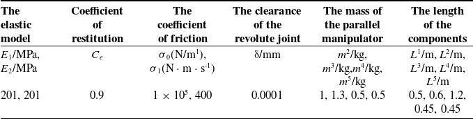
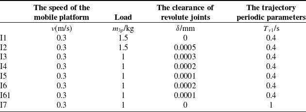
The operating condition parameters.

The mobile platform parameters.

The parameters of the parallel manipulator.

The adjustable parameters.

Substituting Eq. (24) into Eq. (23) yields [Reference Farajtabar, Daniali and Varedi37, Reference Yuwei, Shujin and Bin45]:
 \begin{equation} F_{n}=K\delta ^{n}\left[1+\frac{3\left(1-\left(c_{e}\right)^{2}\right)v_{n}}{4v_{ni}}\right] \end{equation}
The revolute joint friction force with the LuGre friction model [Reference Muvengei, Kihiu and Ikua41, Reference Muvengei, Kihiu and Ikua42] can be expressed as follows:
 \begin{equation} F_{t}=\mu F_{n} \end{equation}
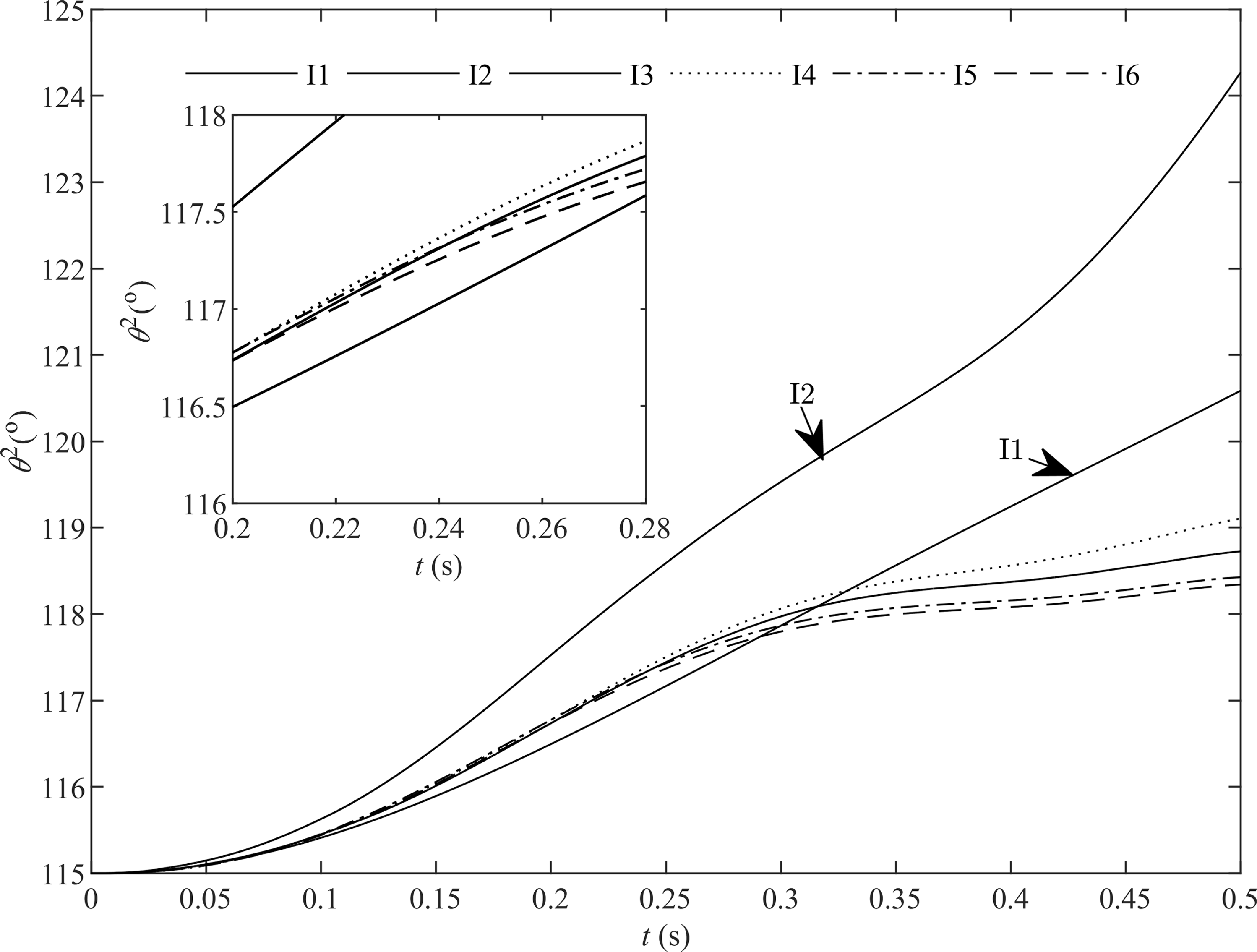
 $\theta ^{2}$
under different conditions.

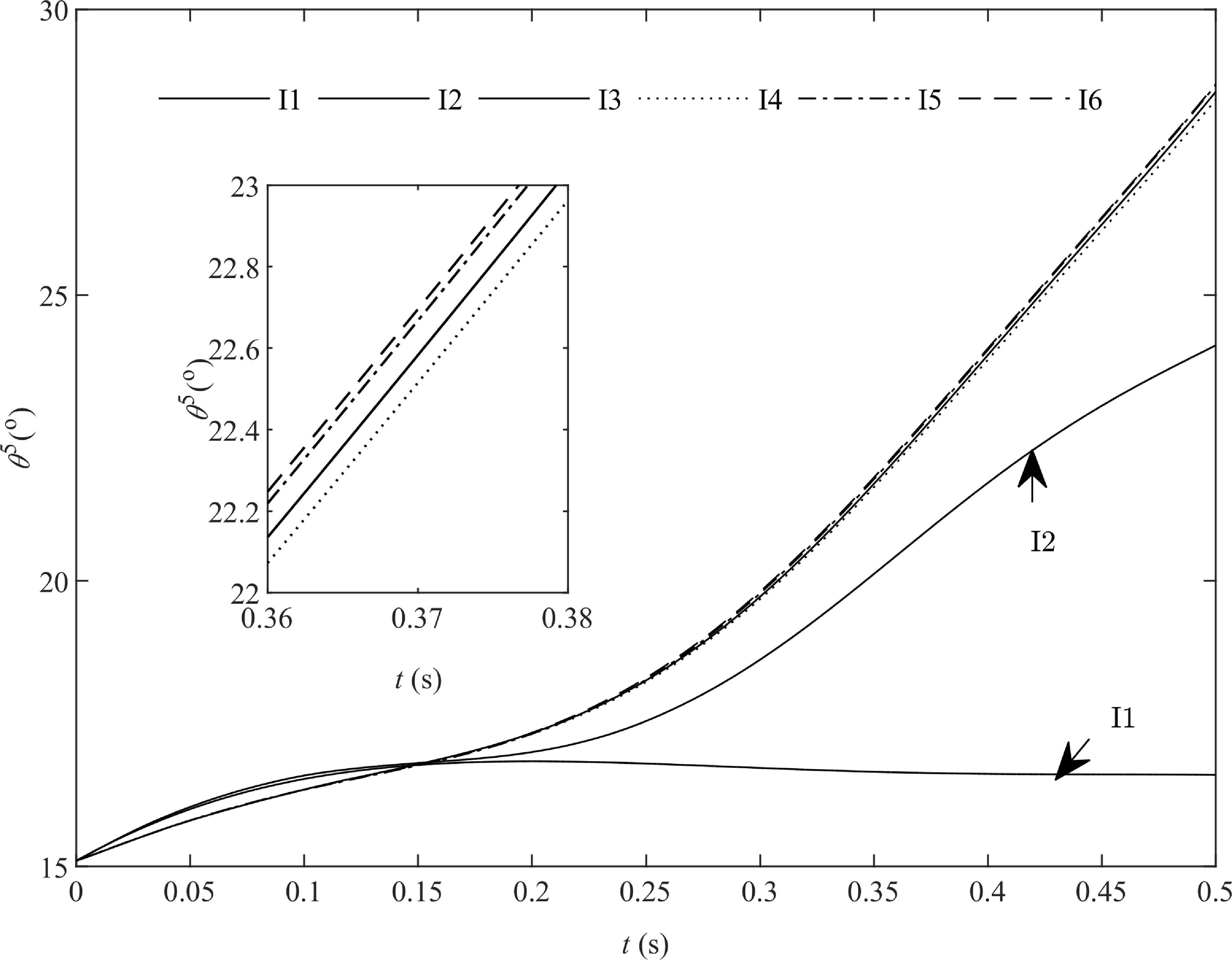
 $\theta ^{5}$
under different operating conditions.

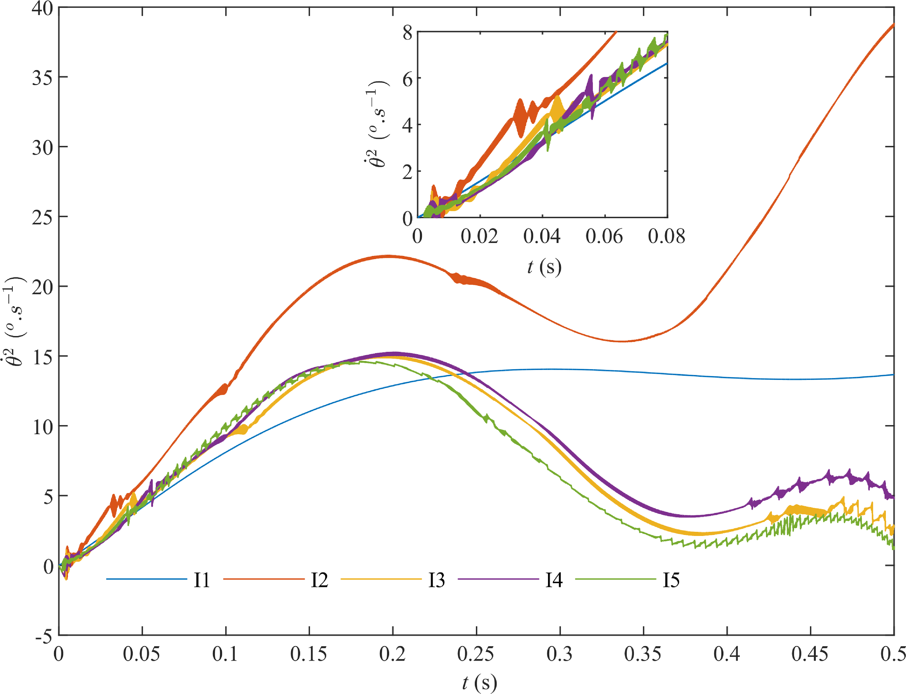
 $\dot{\theta }^{2}$
under different operating conditions.

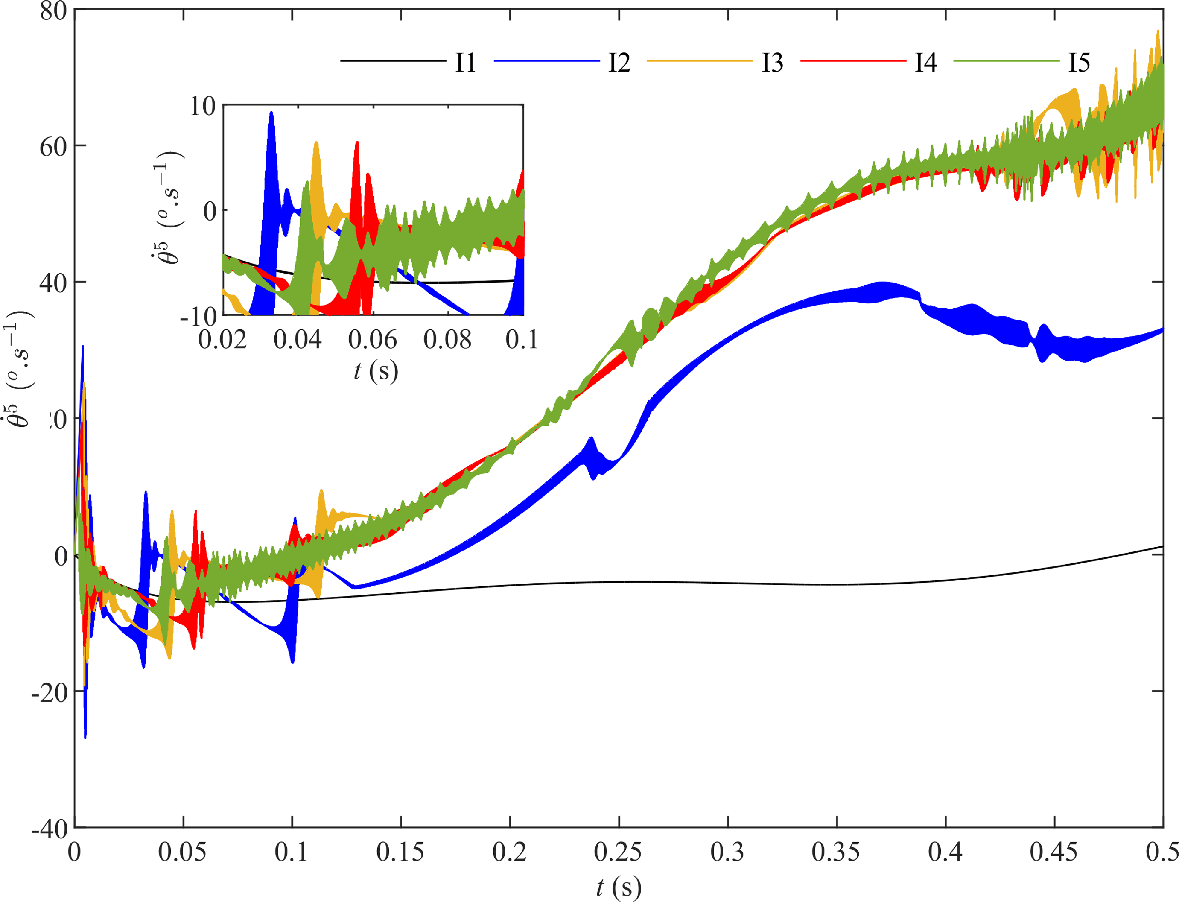
 $\dot{\theta }^{5}$
under different operating conditions.

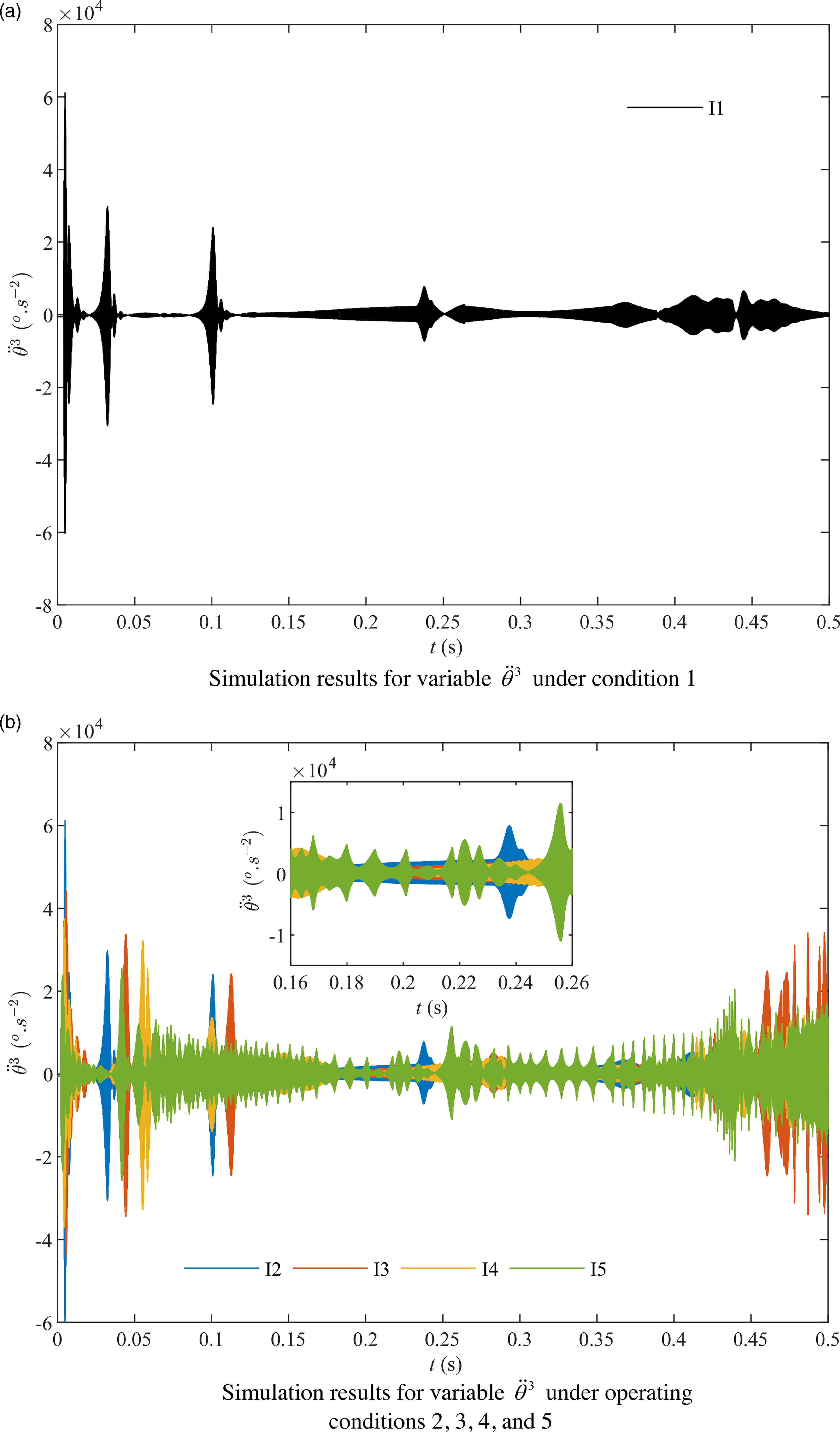
 $\ddot{\theta }^{3}$
under different operating conditions.

Where μ is the instantaneous coefficient of friction;
 $\mu =\sigma _{0}z+\sigma _{1}\dot{z}+\sigma _{2}v_{t}$
; the z is the average deflection of the bristles [Reference Muvengei, Kihiu and Ikua41].
 \begin{equation} z=\frac{v_{t}\mu _{k}+v_{t}\def\negativespace{}\left(\mu _{s}-\mu _{k}\right)\exp\def\negativespace{}\left(-\left| \frac{v_{t}}{v_{s}}\right| \gamma \right)}{\left| v_{t}\right| \sigma _{0}} \end{equation}
 \begin{equation} \dot{z}=v_{t}-\frac{\sigma _{0}\left| v_{t}\right| }{\mu _{k}+\left(\mu _{s}-\mu _{k}\right)\exp\def\negativespace{}\left(-\left| \frac{v_{t}}{v_{s}}\right| \gamma \right)}z \end{equation}
In the equation, z,
 $\sigma _{0} , \sigma _{1}$
, and
 $\sigma _{2}$
are the dynamic parameters of the LuGre friction model, while
 $\gamma , v_{s} , \mu _{s}$
, and
 $\mu _{k}$
are the static parameters of the model. The vector form of the collision impact force and friction force (measured in the coordinate system O
C
-X
C
Y
C
in Fig. 4) for the revolute joint bearing with clearance and friction can be expressed as:
 \begin{equation} \overline{\mathbf{F}}_{nt}^{3}=\left[F_{n}\right.\; \; \; \left.F_{t}\right]_{1\times 2}^{\mathrm{T}} \end{equation}
The
 $F_{n}$
and
 $F_{t}$
are derived from Eqs. (27) and (28). Its description in the global coordinate system is as follows:
 \begin{equation} \mathbf{F}_{nt}^{3}=\mathbf{A}_{c}^{3}\overline{\mathbf{F}}_{nt}^{3} \end{equation}
Similarly, the vector forms of the collision impact force and frictional force on the shaft journal of the revolute joint with clearance and friction can be derived as follows:
 \begin{equation} \mathbf{F}_{nt}^{4}=-\mathbf{F}_{nt}^{3} \end{equation}
Built on the foundation of inverse dynamics of subsequent mobile parallel manipulators (without considering revolute joints clearance), the joint reaction forces and friction forces can be obtained. These forces serve as external forces applied to the moving double serial manipulator.
 $\overline{\mathbf{F}}_{R}^{3}$
is determined through force analysis of each component and is solved using Lagrangian dynamics equations. The detailed derivation of this process is omitted here. The joint reaction force
 $\mathbf{F}_{R}^{i}$
(i = 3, 4) is defined as follows:
 \begin{equation} \mathbf{F}_{R}^{3}=\mathbf{A}_{c}^{3}\overline{\mathbf{F}}_{R}^{3} \end{equation}
 \begin{equation} \mathbf{F}_{R}^{4}=-\mathbf{F}_{R}^{3} \end{equation}
From Eqs. (32) to (35), the external force applied at the opening of the revolute joint with clearance is ultimately obtained as follows:
 \begin{equation} \mathbf{F}_{RC}^{3}=\mathbf{F}_{R}^{3}+\mathbf{F}_{nt}^{3} \end{equation}
 \begin{equation} \mathbf{F}_{RC}^{4}=\mathbf{F}_{R}^{4}+\mathbf{F}_{nt}^{4} \end{equation}
Based on multibody dynamics theory, and by integrating the Newton-Euler method and the Lagrange method, using the independent coordinate method [Reference Yuwei, Minglu, Xinhua, Guangzhu and Bin43–Reference Yuwei, Shujin and Bin45], the dynamic model of the moving manipulator system can be constructed. The expression is as follows [Reference Shabana38]:
 \begin{equation} \mathbf{M}_{i}^{j}\ddot{\mathbf{q}}_{i}^{j}=\mathbf{Q}_{i}^{j} \end{equation}
Where
 $\mathbf{M}_{i}^{j}$
and
 $\mathbf{Q}_{i}^{j}$
are defined as follows:
 \begin{equation} \mathbf{G}_{i}^{j}=\left[\mathbf{I}\; \; \; \mathbf{A}_{\theta }^{j}\overline{\mathbf{u}}^{j}\right] \end{equation}
 \begin{equation} \mathbf{M}_{i}^{j}=\left[\int _{m}\left(\mathbf{G}_{i}^{j}\right)^{\mathrm{T}}\mathbf{G}_{i}^{j}\; dm_{j}\right]=\left[\begin{array}{c@{\quad}c} \mathbf{m}_{RR}^{j} & \mathbf{m}_{R\theta }^{j}\\ \left(\mathbf{m}_{R\theta }^{j}\right)^{\mathrm{T}} & m_{\theta \theta }^{j} \end{array}\right] \end{equation}
 \begin{equation} \mathbf{Q}_{i}^{j}=\left[\begin{array}{l} \mathbf{Q}_{r}^{j}\\ \mathbf{Q}_{\theta }^{j} \end{array}\right]=\left[\begin{array}{l} \; \; \; \; \; \; \; \; \mathbf{F}^{j}\\ \left(\mathbf{F}^{j}\right)^{\mathrm{T}}\mathbf{A}_{\theta }^{j}\overline{\mathbf{u}}_{p}^{j} \end{array}\right] \end{equation}
In the equation, where j=1,2, they represent the mobile parallel manipulator system and the moving double serial manipulator system (the notation is the same below).
 $\mathbf{F}^{j}$
represents an external force, while
 $\overline{\mathbf{u}}_{p}^{j}$
denotes the point of application of the force.
 $\mathbf{M}_{i}^{j}$
is the mass matrix related to the independent variable
 $\mathbf{q}_{i}^{j}$
of the system.
 $\mathbf{Q}_{i}^{j}$
is the second-order velocity inertia force related to the external force (moment) and the variables
 $\mathbf{q}_{i}^{j}$
and
 $\dot{\mathbf{q}}_{i}^{j}$
.
4. Numerical simulation
As mentioned above, from Eqs. (21) and (22), the state vector is defined as:
 $\mathbf{Y}^{j}=[(\mathbf{q}_{i}^{j})^{\mathrm{T}}\; \; \; (\dot{\mathbf{q}}_{i}^{j})^{\mathrm{T}}]^{\mathrm{T}} , \dot{\mathbf{Y}}^{j}=[(\dot{\mathbf{q}}_{i}^{j})^{\mathrm{T}}\; \; \; (\ddot{\mathbf{q}}_{i}^{j})^{\mathrm{T}}]^{\mathrm{T}}$
. Substituting it into the system dynamics equation (Eq. (38)), and after appropriate transformation, we can obtain [Reference Yuwei, Xinhua, Qiyuan, Jiageng and Bin44, Reference Yuwei, Shujin and Bin45]:
 \begin{equation} \dot{\mathbf{Y}}^{j}=f^{j}\left(\mathbf{Y}^{j},t\right) \end{equation}
Equation (42) is a system of first-order ordinary differential equations (ODEs) [Reference Safaeifar and Farshidianfar25] that is solved using the ODE solver in MATLAB 2015. This solver is a variable-step numerical integration method suitable for stiff equations. The specific solution process is shown in Fig. 5.
The simulation process is as follows.
(1) Excluding revolute joint clearances and frictional conditions, the dynamic modeling of a mobile parallel manipulator is conducted to obtain
 $\mathbf{Y}^{1} , \dot{\mathbf{Y}}^{1}$
, and
 $\mathbf{T}^{1}$
through numerical simulation. These values will serve as the initial boundary conditions and known conditions for the subsequent dynamic simulation of a mobile double serial manipulator. “
 $t_{m}$
” and “
 ${\unicode[Arial]{x0394}} t_{0}$
” will be used as the time period and time interval, respectively, for the subsequent dynamic simulation of the mobile double serial manipulator.
(2) Taking into account the clearance in revolute joints and friction conditions, a specific revolute joint of a mobile parallel manipulator is opened, with joint reaction forces and friction forces applied as reaction forces, resulting in the formation of an equivalent mobile double serial manipulator (Fig. 2). The kinematic model C
2 = 0 is established, followed by coordinate separation. The system configuration is described using independent coordinates
 $\mathbf{q}=f^{2}(\mathbf{q}_{i}^{2},t)$
, with
 $\mathbf{Y}^{1}$
and
 $\dot{\mathbf{Y}}^{1}$
obtained in step (1) serving as known boundary conditions.
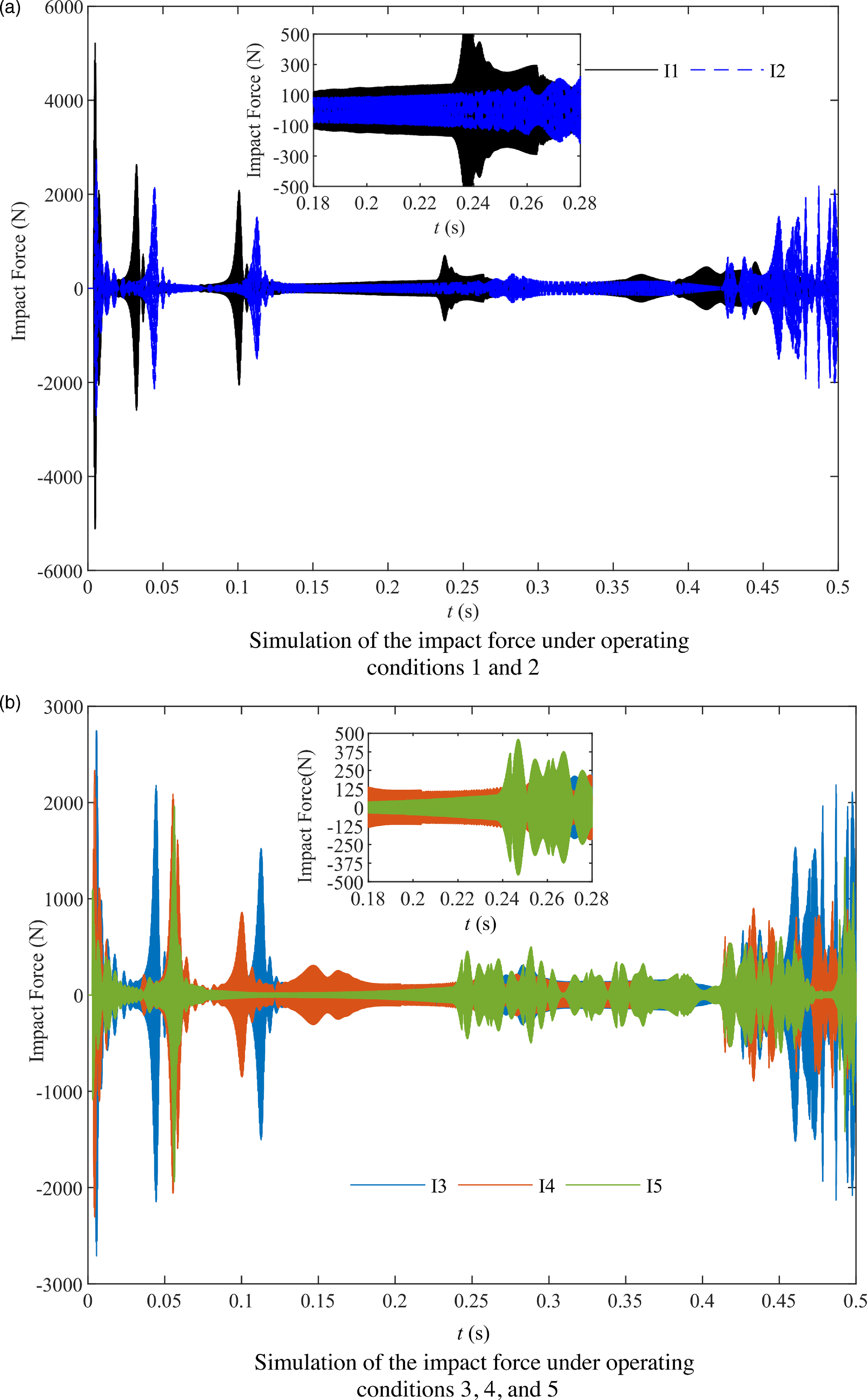
The impact force Fn under different working conditions.

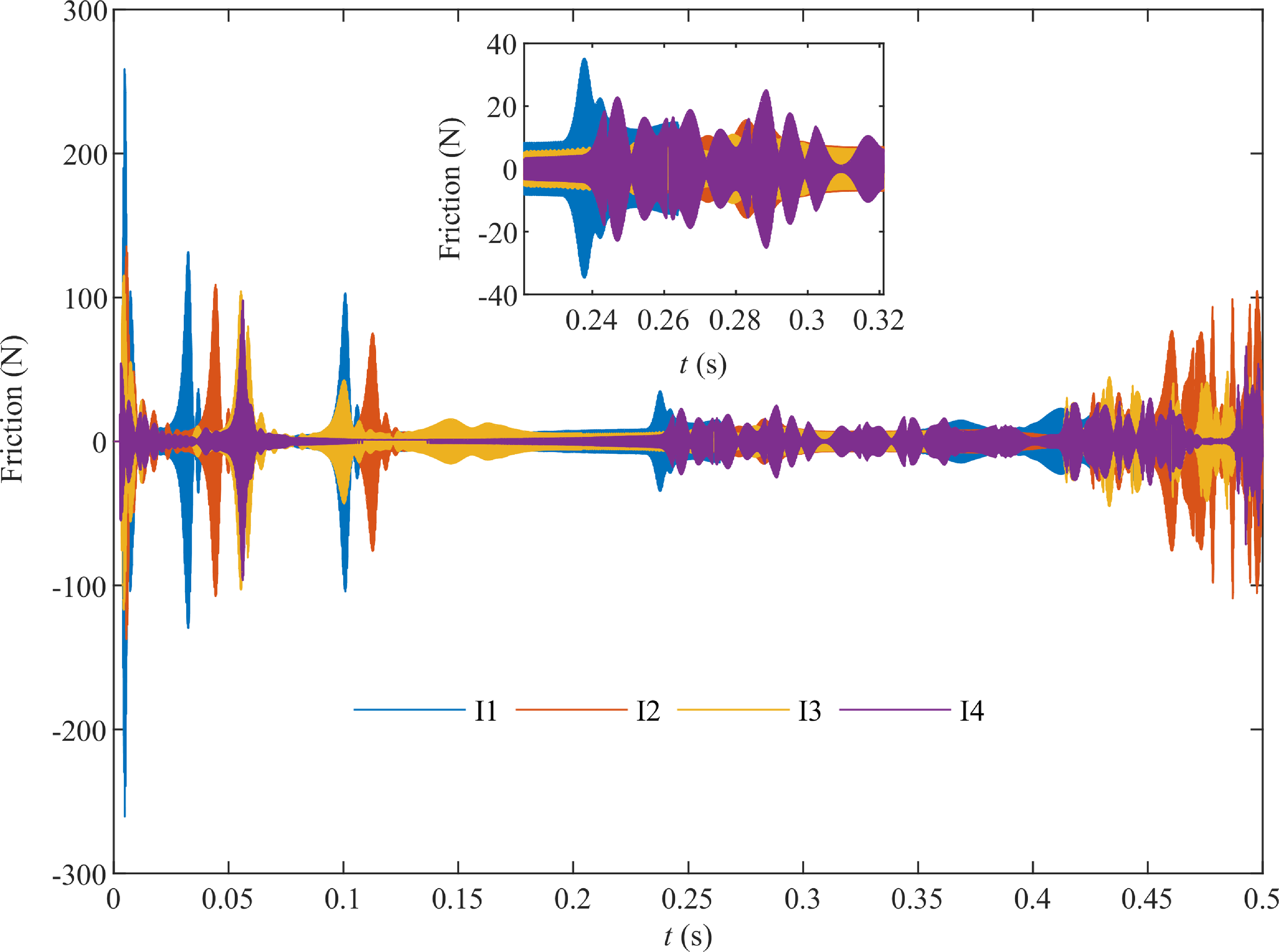
The frictional force Ft under different operating conditions.

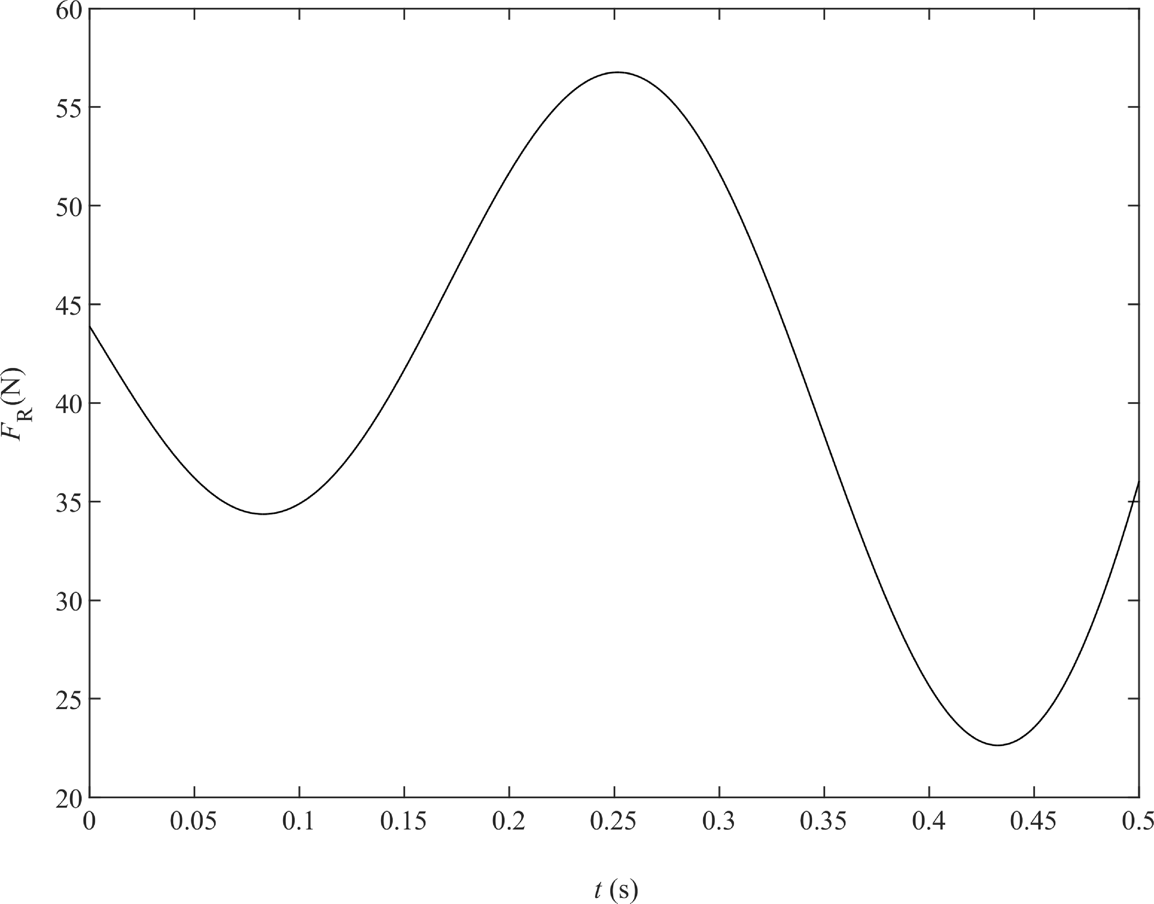
Simulation of the joint reaction force FR.

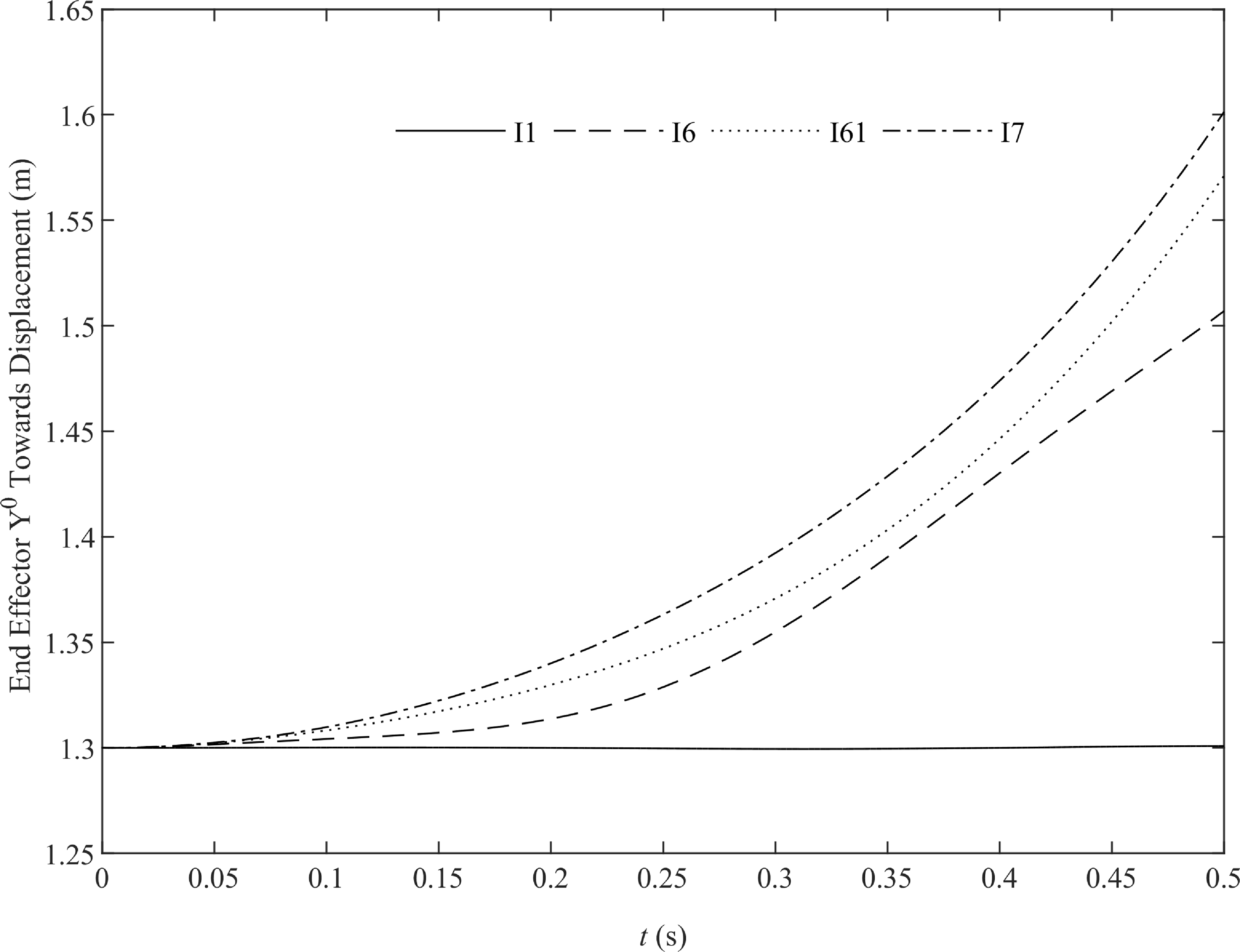
The trajectory of the effector in the Y0 direction.

The impact force Fn under different operating conditions.

(3) Based on step (2), we define simulation time parameters
 $t_{s} , t_{m}$
, and
 ${\unicode[Arial]{x0394}} t_{0}$
. We use
 $\mathbf{T}^{1}$
as the known input driving torque to determine if a collision impact exists. When
 $\delta \leq 0 , \mathbf{F}_{RC}^{3}=\mathbf{0}$
and
 $\mathbf{F}_{RC}^{4}=\mathbf{0}$
. When
 $\delta \gt 0 , \mathbf{F}_{RC}^{3}$
and
 $\mathbf{F}_{RC}^{4}$
are given by Eqs. (36) and (37).
(4) Build a mobile dual-serial manipulator dynamic model and perform numerical simulation to obtain
 $\mathbf{Y}^{2}$
and
 $\dot{\mathbf{Y}}^{2}$
. If the simulation time, t
s
, is not less than t
m
, return to step (3) and carry out iterative numerical simulation until t
s
is less than t
m
.
(5) Perform a comparison calculation of
 $\unicode{x1D6C6}=\mathbf{Y}^{\mathrm{1}}-\mathbf{Y}^{\mathrm{2}}$
. If
 $\unicode{x1D6C6}\gt \unicode{x1D6C6}_{0}$
, then adjust the parameters
 $(k_{v1},k_{v2},T_{v1},v,\delta ,C_{e},m_{3P})$
until
 $\unicode{x1D6C6}\leq \unicode{x1D6C6}_{0}$
is satisfied, and end the numerical simulation.
The parameters used for numerical simulation of mobile parallel and double serial manipulators [Reference Varedi, Daniali, Dardel and Fathi27, Reference Li-Xin and Yong-Gang28] are shown in Tables 1–4.
Some numerical simulation results are shown in Figs. 6–15. Figures 6 and 7 show the numerical simulation of θ 2 and θ 5 for different parameter conditions of the mobile parallel manipulator and the mobile double serial manipulator. By comparison, it can be seen that under the same driving torque T 1, adjusting parameters such as collision penetration depth δ and load m 3p [Reference Yuwei, Xinhua, Qiyuan, Jiageng and Bin44, Reference Yuwei, Shujin and Bin45] lead to different impacts on the system’s dynamic performance from the clearance impact force within the revolute joint. Since the boundary conditions are the same at the start of the simulation, the system output angles are the same at that time. However, as time progresses, the system output shows different characteristics under different parameters.
Curves I1 and I2 correspond to a load of m 3p =1.5 kg. However, curve I2, in comparison to curve I1, considers the impact of varying sizes of revolute joint clearance on the system. This results in a significant difference in output over time, even with the same driving torque T 1 (as shown in Fig. 5) and identical boundary conditions. Curves I3 to I6 correspond to a system load of m 3p =1.0 kg, and adjustments have been made to the tracking trajectory parameters compared to curves I1 and I2, resulting in significant changes in curves I2 and I3 over time. When the load and tracking trajectory are the same, curves I3 to I6 show some similarities in trends compared to other curves, but adjustments to the system’s revolute joint clearance lead to differences in curves I3 to I5.
Curve I6, compared to curve I5, does not consider the effect of joint support reaction forces, that is
 $\mathbf{F}_{R}^{4}=\mathbf{F}_{R}^{3}=\mathbf{0}$
. However, since the difference between curves I5 and I6,
 $\unicode{x1D6C6}$
, is small, it can be concluded that the effect of joint forces
 $\mathbf{F}_{R}^{3}$
and
 $\mathbf{F}_{R}^{4}$
on the dynamic performance of the system is minimal compared to the impact forces
 $\mathbf{F}_{nt}^{3}$
and
 $\mathbf{F}_{nt}^{4}$
caused by relative revolute joint clearance collisions (Fig. 13). Due to space limitations, the corresponding velocity and acceleration simulation results for the same operating conditions will not be discussed in this paper.
Figures 8 and 9 present simulation results of
 $\dot{\theta }^{2}$
and
 $\dot{\theta }^{5}$
values for a mobile double serial manipulator under different parameter conditions. A comparison reveals that due to the absence of consideration for collision impacts of clearance revolute joints in curve I1, the velocity changes are relatively smooth. Conversely, curves I2 to I5 exhibit oscillations at corresponding moments, indicating significant variations in velocity impact during the execution of a predetermined trajectory by the manipulator at different time intervals. As the clearance between revolute joints decreases, the angular velocity variations in curves I3 to I5 generally decrease, aligning with engineering norms. Similarly, the simulation data for
 $\ddot{\theta }^{3}$
in Fig. 10 also demonstrate these characteristics.
Figures 11– 13 show simulations of the impact force, friction force, and joint reaction force in the clearance revolute joint sequentially. In Fig. 11: (1) For the same tracking trajectory of the manipulator, the amplitude of the contact force (as shown by curves I2 and I3) decreases overall with a decrease in load. However, for a specific time period (such as 0.26 to 0.28 s), despite the load decreasing from 1.5 to 1 kg, the amplitude of curve I3 is higher than that of I2, with the opposite result occurring in other stages (such as 0.15–0.22 s); (2) Under the same conditions of the end-effector tracking trajectory and load, the impact forces in different revolute joint clearances correspond to curves I3 to I5. Overall, the impact forces decrease with a decrease in clearance. However, for a specific time period (such as 0.25–0.26 s), despite the clearance decreasing from 0.5 to 0.1 mm, the amplitude of curve I5 is higher than that of the other curves. The opposite result occurs in other stages (such as 0.05–0.06 s). This indicates a complex nonlinear relationship between joint impact force, load, and joint clearance, which is significantly influenced by the end-effector trajectory configuration and is not simply linearly comparable.
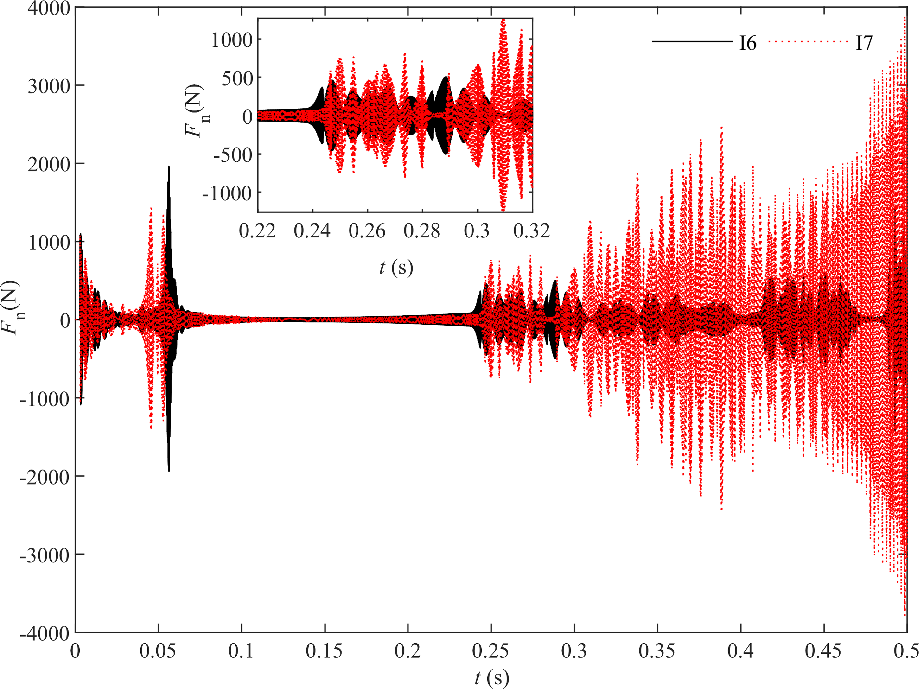
Figure 14 shows the trajectory in the Y0 direction of the end of the manipulator, corresponding to the parameters in Table 4. I1 represents the trajectory of the end of a perfect revolute joint in a double-series moving manipulator, which is consistent with the trajectory of a moving parallel manipulator (without considering revolute joint clearances). Under the condition of considering the impact and friction of revolute joint clearances, the trajectory of the manipulator system’s end point undergoes significant changes at the same driving torque. This simulation result indicates that if the clearances and friction of revolute joints are not taken into account in manipulator trajectory planning, significant tracking errors will occur. This will increase the difficulty of system controller design and will not be conducive to accurate engineering operations of the manipulator system. In Fig. 15, the curves I6 and I7 correspond to the parameters in Table 4, and adjusting the system’s tracking trajectory parameter T v1 results in significant changes in the impact force of clearance revolute joints.
Based on the complete dynamic model of the manipulator mentioned above, the goal is to minimize the impact of clearance in revolute joints through trajectory optimization for a given load condition between two points. This will reduce wear and tear, increase working life, improve system operation accuracy, and decrease controller design costs. Therefore, studying the impact of clearance joints on system dynamic performance is of great engineering significance.
5. Conclusions
The concept of the collision impact direction matrix was introduced and applied for the first time, transforming the mechanical model of a revolute joint with clearances into external forces acting on the system based on multibody dynamics theory. This enhances the comprehensiveness, accuracy, and universality of system dynamic modeling.
Investigated the different influences of joint reaction forces and clearance impact forces on system dynamics. When the clearance joint impact force approaches the joint reaction force, both have significant impacts on system dynamics. In view of enhanced engineering requirements for precise system operation, a comprehensive dynamics model should incorporate impact forces and joint reaction forces together.
Revealed the influence of multiple parameters (such as load, clearance, trajectory, velocity, etc.) on the clearance impact force, emphasizing the importance of comprehensive optimization based on a complete dynamic model to enhance the operational precision of mobile manipulators.
By optimizing the trajectory of the proposed comprehensive dynamics model under given load conditions between two points, it can effectively reduce clearance impact, decrease wear, extend service life, improve precision, and lower control costs, demonstrating the significant engineering significance of the research approach.
This paper primarily investigates the impact of collisions caused by revolute joint clearance on robotic systems and the rationality and effectiveness of corresponding research methods. This paper primarily validates the proposed research method using a two-dimensional planar structure, which can also be generalized to the research and application of three-dimensional mechanisms.
Author contributions
Yuwei Yang developed the methodology, conceived, and designed the study. Xingchang Lv and Jiapeng Yin conducted software analysis, validated the results, and wrote the original draft. Xingchang Lv conducted formal analysis and contributed to writing and editing. Yuwei Yang and Zhaotong Li provided guidance and oversight throughout the project and valuable input to enhance quality. Jutao Wang, Shuo Li, and Haoyu Wang managed the project and contributed to writing and editing. All authors reviewed the manuscript.
Financial support
This work was supported by the National Key R&D Program of China (Grant no. 2017YFB1303502); the National Natural Science Foundation of China (Grant no.10101/70305901).
Competing interests
The authors declare no conflicts of interest exist.
Ethical approval
None.