1. Introduction
The unmanned surface vehicle (USV) is becoming more feasible than humans to deal with various maritime tasks in dangerous and capricious sea environment for its low cost, long endurance and high automation (Deng et al., Reference Deng, Zhang, Gong and Ni2023; Deng et al., Reference Deng, Zhang, Xu, Zhang and Zhou2024; Hu et al., Reference Hu, Gong, Han, Zhu, Yang and Wang2023a, b). Most maritime search and rescue (SAR) tasks concerning the man overboard scenario happen on the surface. Thus, the USV significantly outperforms the other marine crafts in SAR tasks for its better communication and wider assembly with extra sensing facilities, such as the unmanned ariel vehicle (Li et al., Reference Li, Wang, Soares and Ni2024a, b; Wang et al., Reference Wang, Liu, Liu and Sun2023). Tang et al. (Reference Tang, Shi and Zhang2024) investigates the SAR path planning of the USV as a communication relay node between the central command ship and the rescue ship. However, in most cases, the USV can act as the mobile craft undertaking SAR tasks itself. Figure 1 describes the SAR tasks for the USV. The base station first dispatches the SAR tasks for a patrolling USV near the accident. Then, the USV will collect the information about the probable locations of the task points and plan the shortest path to the substation (i.e. Goal in the figure) while covering all these locations. Since the planned path only includes the information of the locations and the sea chart, a more detailed path synthesising the local detected obstacles should be determined in the actual navigation. Thus, it is more practical to employ a bi-layer SAR path planning. Most existing research has focused on the SAR task assignment for multi-agents, and the path planning can be simultaneously addressed. Wu et al. (Reference Wu, Song, Ma, Wu and Han2022) proposed a reinforcement learning based particle swarm optimisation approach for the multiple autonomous underwater vehicle (AUV) system, where task assignment and path planning were merged together. Liu et al. (Reference Liu, Shan and Xu2024) considered the probability of success (POS) in the search environment and proposed a POS-DQN algorithm based on deep reinforcement learning. This algorithm adapted to the complex nature of SAR environments by designing a probability-weighted reward function to train USV agents for optimal search paths. Zhao et al. (Reference Liu, Chen, Wang, Zhang and Gong2024) proposed a bi-layer decision making approach for the USV clusters. The K-means algorithm was used for task allocation and an improved self-organising map (SOM) algorithm was developed for task planning with the time constraints. Liu et al. (Reference Liu, Song, Bucknall and Zhang2019) combined the SOM with the fast-marching method (FMM), and the issues of energy consumption and communication distance can be addressed. Taking into account the distributed communication between USVs, the Tabu dynamic consensus-based auction algorithm was adopted in the interception task assignment (Du et al., Reference Du, Lu, Cheng, Zhang and Zou2021). Xue et al. (2021) proposed an exact algorithm to minimise the total max task time based on the Hungarian algorithm, and the obstacle avoidance was realised by using the FMM. Yao et al. (Reference Xue, Yao, Lou and Zhang2023) fabricated an overall decision and control framework for multiple USVs, which included the task assignment by the spectral clustering method, path planning by SOM, guidance by the line-of-sight algorithm and path tracking by active disturbance resistance control. Chakraa et al. (Reference Chakraa, Guerin, Leclercq and Lefebvre2023) concluded the current optimisation methods for the task allocation of the multi-robot system, which covered the SAR task allocation of the USVs. The SAR tasks were also addressed in the coverage path planning. Cho et al. (Reference Cho, Park, Lee, Shim and Kim2021) put forward a two-phase SAR coverage path-planning scheme of multi-USVs, where the mixed-integer linear programming was employed to derive the optimal coverage paths with the grid-based search area decomposition. Wu et al. (Reference Wu, Cheng, Chu and Song2024) considered the drift trajectory prediction and planned the SAR coverage path by using reinforcement learning. Qin et al. (Reference Qin, Zhou, Han and Xue2024) proposed a bi-level path-planning scheme for the AUV, where the triggering replanning of the planned coverage path was conducted for the detected SAR. There are mainly two shortcomings of the above research. First, the planned path for SAR is unchangeable after decision, which is not flexible for the locally detected obstacles. Second, these algorithms all assumed that there are adequate USVs for exploration and every task point must be passed. In reality, a SAR task point may only imply one probable location of the dropped persons and there are limited USVs for numerous task points. Scanning all the task points will prolong the task time and degrade the survival rate of the dropped persons.
Description of SAR tasks for USVs.

The completion of SAR tasks also relies on the selected path-planning algorithms. The global planning should cover as many SAR task points as possible. Although some path-planning algorithms like Dijkstra, A* (Liang et al., Reference Liang, Zhang, Watanabe and Deng2021; Wang et al., Reference Wang, Mao, Mou, Zhang and Li2025), dynamic fast Q-learning (Hao et al., Reference Hao, Du and Yan2023) and plant grow route (Bai et al., Reference Bai, Li, Xu and Xiao2023) have shown their capabilities to deal with single goal convergence with obstacle avoidance, they are not efficient in wide-range exploration and quick calculation, and are therefore not fit for SAR path planning. In comparison, the RRT algorithm has the advantage of fast exploration in high environmental complexity, which is preferred in SAR. To solve the non-optimal path problem in RRT, RRT* was proposed as a landmark variant to ensure asymptotic optimality (Karaman et al., Reference Karaman, Walter, Perez, Frazzoli and Teller2011). Further, to improve the search efficiency, the RRT*-smart (Islam et al., Reference Islam, Nasir, Malik, Ayaz and Hasan2012), the Informed RRT* (Gammell et al., Reference Gammell, Srinivasa and Barfoot2014), the Quick-RRT* (Jeong et al., Reference Jeong, Lee and Kim2019) and the F-RRT* (Liao et al., Reference Liao, Wan, Hua, Ma, Zhu and Qing2021) were progressively developed. Huang et al. (Reference Huang, Fan and Sun2024) modified the RRT with a rising density gradient from the start to the goal for the guide points, which facilitated the path convergence. Cui et al. (Reference Cui, Wang, Xiong, Mei and Wu2024) combined the mechanisms of sparse sampling, dynamic goal-biased strategy and new parent node creation together, which resulted in an MQ-RRT* algorithm offering a shorter and smoother path than the Q-RRT*. The above literature utterly pursued the shortest path at the expense of the exploration ability of the RRT algorithm, so it was not applicable to the SAR tasks that require wide-range exploration. In fact, it is more practical to establish a discrimination mechanism for the SAR tasks while maintaining the exploration capability of RRT.
To cope with dynamic and unknown environmental information, the local path planning for the USV should be secure and fast in computation. Some typical local path-planning algorithms include the dynamic window approach (Zhang et al., Reference Zhang, Zhu, Xue, Deng and Qin2024), the vector field (Yao and Cao, Reference Yao and Cao2020), the artificial potential field (Liu et al., Reference Liu, Shan and Xu2024) and the bio-heuristic optimisation (Lyridis, Reference Lyridis2021). In recent years, deep reinforcement learning was also adopted in local path planning for the enhancement of computing capacity (Du et al., Reference Du, Zhu, Wang, Han and Qiao2024). Among them, the APF stands out for its simplicity in calculation and lucid mathematical description. Lyu et al. (Reference Lyu, Liu, Guo, Tan, Fu, Sun, Zhao, Zhang and Yin2024) employed the APF for maritime collision avoidance while considering the international regulations for preventing collision at sea. Li et al. (Reference Li, Wang, Soares and Ni2024) combined the APF with the ship’s motion model, and the model prediction control with the event-triggered mechanism was employed for seeking the inverse gradient direction of the potential field function. There are mainly two shortcomings of the APF algorithm: (1) it is possible to fall into the local optimum in a complex environment; (2) path oscillation is easy to occur near the endpoint. For the bi-layer path-planning framework, these problems may lead to the inconsistency between the global planned path and the local one, and also the failure of SAR tasks.
Motivated by the above challenges, this paper proposes a bi-layer SAR path-planning framework for a single USV with the SAR tasks already allocated. Different from the previous outcomes, we consider the limited SAR capability of a USV and not all possible task points must be covered. The CNN is employed to establish a discrimination mechanism of the global planned path and the local path planning was conducted by improving the APF. Mainly, this paper has three contributions.
-
• A bi-layer path-planning framework is proposed to address the SAR problem. The global path-planning component is designed to cover the majority of SAR task points across an extensive maritime chart, while the local path-planning component is used to manage dynamic variations surrounding the USV. This framework significantly enhances the efficiency of SAR operations at sea. Additionally, it improves the practicality of executing missions in complex maritime environments, ensuring a more effective response to emergencies.
-
• This paper wields the rapid exploration capacity of RRT to generate the global path for SAR. By using the image processing of CNN with a prescribed principle, it is easy to judge whether the planned path is rational for SAR. This discrimination mechanism for global path planning is simple and useful.
-
• This paper improves the APF to better suit the SAR tasks. By adopting mandatory movement and endpoint convergence, the IAPF can ensure the avoidance of locally detected obstacles and the proximity of task points while successfully solving the path oscillation problem.
The remainder of this paper is organised as follows. The problem formulation and the used methods are depicted in Section 2. The proposed CRRT-IAPF algorithm is described in Section 3. The simulation is presented in Section 4. Section 5 concludes the entire work.
2. Preliminaries
In this section, the paper describes the assumptions of the USV path-planning algorithm and introduces the underlying RRT algorithm and APF algorithm to set the stage for the new methods that will be problematised later in the paper.
2.1. Problem formulation
In this paper, a single USV is tasked with completing SAR operations while navigating efficiently from the starting point to the target location in the sea. The path planning for the USV is divided into global and local components. For SAR tasks, the USV only needs to approach within a certain range of the task location, as its detecting devices can identify targets from a predetermined distance. The primary objective of this paper is to develop an effective path-planning strategy that enables the USV to reach its endpoint quickly while maximising the number of SAR tasks completed, ensuring comprehensive coverage of potential rescue areas.
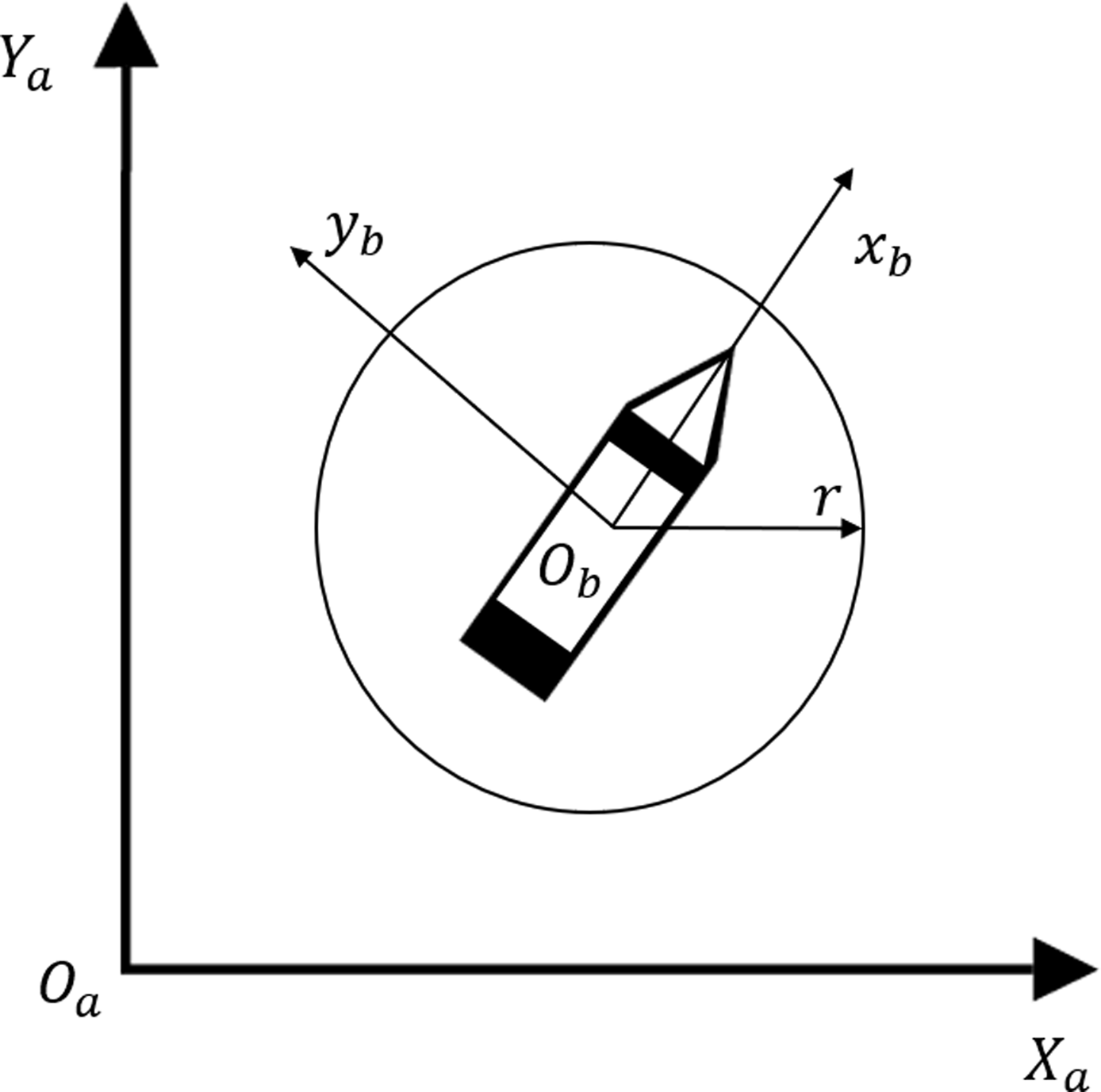
The coordinate relationship of the USV in path planning is shown in Figure 2, where
 ${x_a}$
and
 ${y_a}$
represent the earth-fixed frame,
 ${x_b}$
and
 ${y_b}$
represent the body-fixed frame, and
 $r$
represents the search range. The formulation of obstacles in global path planning and local path planning are shown in Figures 3 and 4, respectively. The obstacles in global path planning will be inflated as circles and the obstacles in local path planning will be reconstructed as repulsion points with repulsion ranges.
Coordinate relationship of USV.

Global path planning obstacle formulation for USV.

Local path planning obstacle formulation for USV.

2.2. Rapid-exploration random tree algorithm
The RRT algorithm is a widely used method for path planning in complex environments. The implementation process begins with the initialisation of a tree that contains a starting node representing the initial configuration of the system. The algorithm then enters a loop where it generates random samples from the configuration space. For each sample, the nearest node in the existing tree is identified. Subsequently, the algorithm attempts to extend the tree towards the random sample by creating a new node positioned within a specified step size from the nearest node. If this new node is valid – meaning it does not collide with any obstacles – it is added to the tree. This iterative process continues until the tree reaches a goal configuration or a pre-defined number of iterations is exhausted. Upon reaching the goal, the path can be extracted by backtracking from the goal node to the starting node, thereby yielding a feasible navigation solution for the given environment. Although the tree expansion method allows RRT to explore the entire space without becoming trapped in local optima, it often results in non-optimal paths. To address this issue, various extensions of the RRT algorithm have been developed. However, these optimisations are not suitable for path planning in SAR tasks.
2.3. Artificial potential field algorithm
The APF algorithm is used for mobile robot path planning, which guides the robot towards the goal and avoids obstacles by modelling the gravitational and repulsive fields around the robot. Generally, the obstacles constitute the repulsive fields while the endpoint the gravitational field. By referring to the negative gradient of the potential field, the resultant force acting on the agent can be obtained.
If the position of agent is
 $\left( {x,y} \right)$
and the position of obstacle is
 $\left( {{x_g},{y_g}} \right)$
, then the gravitational potential field function is
 $$_{att}\left( {x,y} \right) = {1 \over 2}\eta [{(x - {x_g})^2} + \left( {y - {y_g}{)^2}} \right]$$
where
 $\eta $
is the postive gravitation coefficient. Then, the attracting force on agent is the negative gradient of that potential field,
 $${F_{att}} = \eta \sqrt {{{(x - {x_g})}^2} + {{(y - {y_g})}^2}} $$
The distance between the agent and the obstacle determines the repulsive potential field. When the agent does not enter the influence range of the obstacle, the value of its potential energy is zero. Otherwise, a larger distance between the two results in a smaller repulsive force on the agent, and a smaller distance is results in a larger repulsive force. The repulsive potential field function is set as
 \begin{align}{U_{re}} = \left\{ {\matrix{ {{1 \over 2}k{{({1 \over {\rho \left( {q,{q_o}} \right)}} - {1 \over {{\rho _o}}})}^2}} \hfill & 38; {0 \le \rho \left( {q,{q_o}} \right) \le {\rho _o}} \hfill \cr 0 \hfill & 38; {\rho \left( {q,{q_o}} \right) \ge {\rho _o}} } } \right.\end{align}
where
 $k$
is a positive scale factor,
 $\rho \left( {q,{q_o}} \right)$
is a vector with the direction pointing from the obstacle to the agent,
 $\left| {q - {q_o}} \right|$
denotes the distance between the agent and the obstacle, and
 ${\rho _o}$
is the constant indicating the influence range. Then, the corresponding repulsive force is the negative gradient of the repulsive field,
 \begin{align}{F_{re}} = \left\{ {\matrix{ {k\left( {{1 \over {\rho \left( {q,{q_o}} \right)}} - {1 \over {{\rho _o}}}} \right){1 \over {{\rho ^2}\left( {q,{q_o}} \right)}}{{q - {q_o}} \over {q - {q_o}}}} \hfill & 38; {0 \le \rho \left( {q,{q_o}} \right) \le {\rho _o}} \hfill \cr 0 \hfill & 38; {\rho \left( {q,{q_o}} \right) \ge {\rho _o}} } } \right.\end{align}
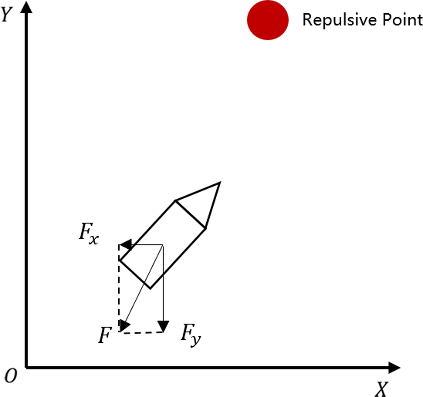
The principle of the APF algorithm is illustrated in Figure 5. However, the APF algorithm encounters two significant challenges: path oscillation as it approaches the endpoint and the tendency to get trapped in local optima when navigating environments with a high density of obstacles.
Schematic diagram of APF.

3. The proposed CRRT-IAPF algorithm
This section describes the CRRT-IAPF path-planning algorithm for USV in the SAR mission in two subsections. The flowchart of the algorithm is shown in Figure 6. To better describe what is being studied, the USV path-planning problem discussed in this paper has the following assumptions.
-
• Large obstacles will be bypassed by the ship in the global path planning, while small obstacles will be handled as repulsive points in the local path planning.
-
• The task points are defined as the locations with probable or affirmative task occurrence, which will be reconstructed as the attracting points in local path planning.
Flowchart of CRRT-IAPF algorithm.

3.1. Convolutional neural network modelling rapid-exploration random tree
This subsection describes the global path planning CRRT algorithm, the algorithm in this subsection is divided into two parts, namely path generation and path discrimination.
3.1.1. Rapid-exploration random tree path generation
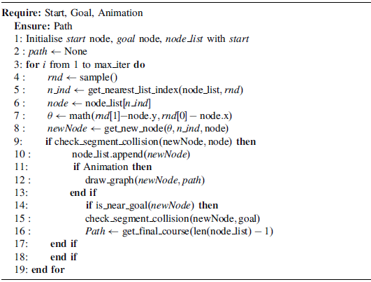
The first step is to generate the path diagrams, which are employed for the global planning and the training of the CNN. By resorting to Algorithm 1, the path diagrams can be obtained by using the RRT method, where the inflated obstacles, the coordinates of start and end points, should be initialised. After generating the path, the task points are added to the path diagrams. The ship is preset with a detecting range. If more than 70% of task points can be detected during the voyage, the RRT path is categorised into the optimal path diagram dataset and otherwise, the non-optimal. To increase the training samples of optimal path, the task points are generated by using the normal distribution along the RRT path. To achieve the efficient training of the CNN, only the red, green and blue colours are employed in the diagram. With the sufficient samples generated by Algorithm 1 and the task points added, the CNN can be trained and learns to identify whether the generated RRT path is optimal or not.
RRT Path Generation

3.1.2 Rapid-exploration random tree path discriminator
The RRT path discriminator will be done by a CNN. As is shown in Figure 7, it contains two convolutional layers, two pooling layers and one fully connected layer. In the forward propagation, the input passes through Conv1, the ReLU activation function and then the maximum pooling layer. The output of the first maximum pooling layer passes through Conv2, ReLU activation and then the second maximum pooling layer. The output of the second maximum pooling layer is flattened and then passes through the fully connected layer. The final output represents the predicted category probabilities of the optimal and the non-optimal paths for each image. The dataset is divided into training, testing and validation by 7:2:1. The cross-entropy loss is chosen as the loss function and the Adam optimiser is adopted with the learning rate of 0.001.
CNN structure diagram.

Before the training, the image should be first rotated and cropped to 128×128 size. According to its RGB colours, the image is converted to a multidimensional array, the dimensions of which include the channel, the height and the width.
3.2. Improved artificial potential field algorithm
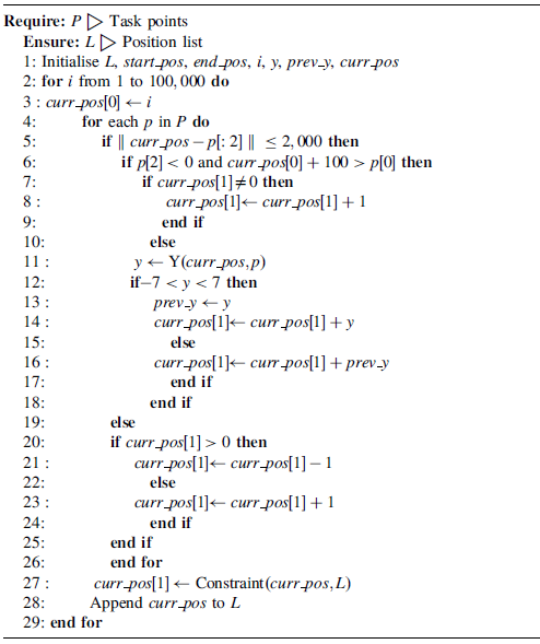
This subsection presents the IAPF algorithm for the local path planning, which makes simplification and improvement while retaining the core thought of the traditional APF algorithm. The pseudo-code is given in Algorithm 2.
3.2.1. Algorithm design and analysis
In the traditional APF algorithm, the obstacle is deemed as the repulsion point and the end point, the gravitational point. The core is to calculate the gradient of the potential field superimposed on the USV. Then, the next position is calculated based on the magnitude and the direction of the gradient. Since the convergence of the planned path is not considered, this algorithm inevitably leads to the problems of path oscillating and local optimum.
Define the XY-coordinate, where the X-axis is aligned from the start point of the USV to its end point. By decomposing the combined force along the coordinate axes in Figure 8, it is found that the USV is subjected to many forces in the negative direction of the X-axis, which deteriorates the path convergence and causes the oscillation. For this problem, the proposed IAPF algorithm ignores the repulsive forces in the X-axis direction and only analyses the forces in the Y-axis direction.
Vector analysis of USV repulsed by repulsion point.

Reestablish the repulsive potential field function as
 $$U = \eta \sqrt {{{(x - {x_o})}^2} + {{(y - {y_o})}^2}} $$
 $$Y = {{\partial U} \over {\partial y}} = \eta \left( {y - {y_o}} \right){1 \over {\sqrt {{{(x - {x_o})}^2} + {{(y - {y_o})}^2}} }}$$
 $$\eta = {k \over {\sqrt {{{(x - {x_o})}^2} + {{(y - {y_o})}^2}} }}$$
 $$Y = {{k\left( {y - {y_o}} \right)} \over {{{(x - {x_o})}^2} + {{(y - {y_o})}^2}}}$$
where
 $\left( {x,y} \right)$
is the current position,
 $\left( {{x_o},{y_o}} \right)$
is the obstacle position and
 $k$
is the weighting factor. Since only the force in the Y-axis direction is required, it is calculated from the partial derivative of
 $y$
to
 $U$
in (6). Unlike the customary APF algorithm, where the original weight
 $\eta $
is constant, the IAPF makes
 $\eta $
to increase as the distance decreases, see (7). By substituting (7) to (6), (6) can be further simplified as (8).
In the proposed IAPF algorithm, the force in the X-axis direction is ignored and assumed to be zero. In each time step, (8) is used to calculate the current repulsive force of
 $\left( {{x_o},{y_o}} \right)$
in the Y-axis direction. Not to consider the convergence in the Y-axis direction, the next position
 ${y_{n + 1}}$
is calculated by
 $${y_{n + 1}} = {y_n} + {Y_t}$$
where
 ${Y_t}$
is the superposition of
 $Y$
through current gravitational and repulsive potential fields. To eliminate the follow-up influence of passed attracting and repulsive points on path planning, the superposition of
 $Y$
does not involve the points with the passed X-coordinate.
To facilitate the convergence in the Y-axis direction, the IAPF algorithm further involves the constraint functions. Then, (9) is modified as (10) with the constraint functions of (11) and (12),
 $${y_{n + 1}} = \left( {1 - {\rm{\Phi }}\left( x \right)} \right)\left( {{y_n} + {\rm{\Psi }}\left( x \right){Y_t}} \right)$$
 $$\Psi \left( x \right) = 1 - {({x \over {{x_n}}})^{24}}$$
 $$\Phi \left( x \right) = {({x \over {{x_n}}})^{10}}$$
Equation (11) can constrain the update of
 $y$
around the end point and (12) can ensure that the path eventually converge to the end point. The variation of
 ${\rm{\Psi }}\left( x \right)$
and
 ${\rm{\Phi }}\left( x \right)$
is shown in Figure 9. The improved IAPF algorithm, in comparison with the original version, not only designates the endpoint as a gravitational point, but also permits the selection of additional critical points as gravitational points. This enhancement is essential for effectively executing SAR tasks.
Variation of constraint functions.

IAPF Algorithm

4. Simulation
This section carries out the simulation to verify the effectiveness and superiority of the proposed CRRT-IAPF algorithm. The SAR tasks are modelled with only approximate locations and the evaluation function is constructed. Through the comparison, the effectiveness and superiority of the IAPF algorithm and the CRRT-IAPF algorithm are sequentially substantiated.
4.1. Evaluation function
The evaluation functions are proposed to evaluate the search and rescue capability of the proposed algorithm. The purpose of the evaluation function presented below is to assess the effectiveness of the SAR mission. It emphasises the analysis of how the pathway balances various metrics to achieve optimal rescue outcomes. In the simulation, the USVs are assumed to be capable of discovering the dropped persons in a certain detecting range. If the task point is located within the detecting range of the USV along the planned path, one can deem that the task point is successfully searched. Thus, the first evaluation function is designed to evaluate the search success rate in the entire voyage, namely
 $$\theta = {t \over T} \times 100\% $$
where
 $t$
is the number of task points searched and
 $T$
is the total number of task points.
The second evaluation function is designed to evaluate the rescue success rate in the entire voyage, namely the survival rate of the dropped person. For the task point
 $\left( {{x_t},{y_t}} \right)$
along the path, its straight-line distance towards the beginning path point
 $\left( {{x_0},{y_0}} \right)$
is written as
 $${l_t} = \sqrt {{{({x_t} - {x_0})}^2} + {{({y_t} - {y_0})}^2}} $$
One can follow from the thought that the more directly the ship sails towards the task point, the higher the rescue success rate will be. Thus, define a rescue intermediate variable as
 $${P_t} = \left( {1 + \alpha } \right){l_t} - {L_t}$$
where
 $\alpha $
is defined as the positive survival coefficient of the task point and
 ${L_t}$
denotes the length of the planned path while the
 $t$
th task point is successfully searched. While
 $\alpha $
is larger, it can be inferred from (15) that
 ${P_t}$
is apt to be positive. Otherwise,
 ${P_t}$
is apt to be negative. Thus, we can define the rescue success rate
 $\gamma $
by counting the number of positive
 ${P_t}$
along the entire voyage, namely,
 $$\gamma = {{\sum\nolimits_{t = 1}^T \mu \left( {{P_t}} \right)} \over T} \times 100\% $$
 \begin{align}\mu \left( x \right) = \left\{ {\matrix{ 1 \hfill & 38; {x \ge 0} \hfill \cr 0 \hfill & 38; {x \lt 0} \hfill \cr {} \hfill & 38; {} \hfill \cr } } \right.\end{align}
In the simulation,
 $\alpha $
is uniformly set to be 0.6.
4.2. Advantages of IAPF
By comparing with the APF algorithm, the advantages of the IAPF algorithm is demonstrated through the simulation. As a straight global planned path, the XY-coordinates of the starting point and the end point are set to be (0, 0) and (0, 99), and five repulsive points are initiated along the path. Without considering the SAR tasks, no attracting points should be involved. Then, the local planned paths of the two comparative algorithms are shown in Figure 10. With the SAR tasks considered, we replace the two repulsive points in the above situation with the attracting points. Set both the gravitational and the repulsive weights as
 $k = 50$
. By wielding the IAPF, the local planned paths with the SAR tasks are given in Figure 11.
Local path planning for APF and IAPF.

IAPF path planning with attracting points.

It is observed from Figure 10 that although both the algorithms successfully track the end point and circumvent the local repulsive points, the path of the local planned APF is oscillatory near the end point. This phenomenon is produced by the resultant force of the last repulsive point and the end point. By the merit of the Y-convergent mechanism, the path oscillation is eliminated in the proposed IAPF. It is shown in Figure 11 that the proposed IAPF can successfully approach the dropped persons while considering the SAR tasks.
4.3. SAR task simulation
This section verifies the effectiveness of the proposed CRRT-IAPF with the SAR tasks. The customary RRT algorithm and the target search APF (TS-APF) are set for comparison. The TS-APF algorithm follows the thought to connect all the task points and employ the APF for local path planning. Before the implementation of CRRT-IAPF, the CNN should be trained according to the procedure in Section 3.1.1. One of the training samples and the evolution of training loss are shown in Figure 12. In this simulation, a real sea chart of Figure 13 is selected, where the islands are inflated as circular obstacles. Subsequently, the task points and the repulsive points for local path planning are randomly generated, see Figure 14.
Sample of CNN and evolution of training loss.

Actual chart.

Construction of path planning environment.

Figure 15 displays the final planned paths of the three schemes. By referring to Section 4.1, the values of evaluation functions and planned path lengths are presented in Table 1. Because the customary RRT considers no SAR tasks, it possesses the lowest search success rate and rescue success rate, but renders the shortest length of the planned path. As the TS-APF can directly track the task points, it has a search success rate of 100%, but the longest path length. It can be inferred from (15) that the longer and the more sophisticated path will lead to a lower rescue success rate. Thus, the rescue success rate of the TS-APF is degraded. In comparison, the proposed CRRT-IAPF can compromise between the search success rate and the rescue success rate, and the phenomenon to sacrifice the survival rate of the subsequent task points for some outlier task points is prevented. This point can be explained from two aspects. First, the discrimination mechanism in the CRRT can filter out the outlier task points far away from the planned path. Second, the IAPF can ensure the final convergence of the planned path to the end point in the path segment without oscillation. One can find a lower search success rate and a higher rescue success rate of the CRRT-IAPF than the TS-APF in Table 1. A more intuitive comparison of evaluation functions can be observed in the histogram of Figure 16. Moreover, it can be observed in Figure 15 that the planned path of the CRRT-IAPF can be divided into five segments. In each segment, the IAPF is employed to plan the local path, which is shown in Figure 17. The simulation results indicate that, compared with other algorithms, the proposed CRRT-IAPF algorithm outperforms in all three metrics of the evaluation function. It successfully rescues the most targets and the planned route is deemed the optimal path for fulfilling the SAR task.
Comparison of planned paths.

Results of evaluation functions

Histogram of evaluation functions.

Each path segment of IAPF algorithm.

5. Conclusions
This paper addresses the path planning problem of the USV with SAR tasks. A novel path planning algorithm called CRRT-IAPF is proposed, which copes with global path planning with CRRT and local path planning with IAPF. The CNN is employed to judge whether the candidate path generated by the RRT algorithm is optimal and construct a filter mechanism of global path planning. For the local path planning, the traditional APF method is improved with mandatory X-axis movement and endpoint convergence, such that the problem of path oscillation can be solved. With the new evaluation functions, the simulation is conducted to verify that the proposed CRRT-IAPF algorithm has the best rescue success rate with SAR tasks. In the future, we will investigate the modification of CRRT-IAPF to the path planning of multiple USVs, which makes a more efficient SAR task.
Funding statement
This work is partially supported by the Natural Science Foundation of China (No.52101375), the Hebei Province Natural Science Fund (Nos. E2024203179, E2022203088), the Innovation Capacity Enhancement Program of Hebei Province (No. 24461901D), and the Joint Funds of the National Natural Science Foundation of China (No. U20A20332).