

I. INTRODUCTION
Magnesium has generated a lot interest in the field of biomedical implants recently, owing to its biodegradable nature. Reference Witte, Hort, Vogt, Cohen, Kainer, Willumeit and Feyerabend1,Reference Witte2 Its density and mechanical properties are close to that of the human bone tissue, making it particularly attractive for orthopedic and craniofacial implants. Reference Witte, Hort, Vogt, Cohen, Kainer, Willumeit and Feyerabend1,Reference Kirkland3 There has also been interest toward the application of magnesium and its alloys in cardiovascular stents, meshes, as well as other sutures. Reference Witte, Eliezer and Cohen4 Additionally, Mg and its alloys have several applications in the automotive industry. Reference Pollock5 In most of these applications, the mechanical properties and behavior are key for optimum performance. The deformation mechanisms on magnesium single crystals were first investigated several decades ago using compression as the primary mode of deformation in these studies. Reference Reed-Hill and Robertson6–Reference Kelley and Hosford9 This was used to observe the slip and twinning mechanisms when stress was applied along different crystallographic directions involved in the deformation of Mg. With the development of modern characterization techniques, such as severe plastic and high-strain-rate deformation, nano indentation, electron backscatter diffraction (EBSD), high resolution transmission electron microscopy, and crystal plasticity modeling have been used to obtain more accurate information on the deformation microstructure and the Critical Resolved Shear Stresses (CRSS) of the active slip and twinning systems. Reference Kitahara, Maruno, Tsushida and Ando10–Reference Al-Samman, Molodov, Molodov, Gottstein and Suwas16 Despite all these advances, the crystallographic mechanisms of hcp plasticity are still poorly understood in various aspects.
Recent publications have shown that the mechanical behavior of an Mg single crystal can be modified considerably by just varying the orientation without the need to add alloying elements. Reference Hartt and Reed-Hill17–Reference Ando, Koike and Sutou19 It was observed that deformation twins affect ductility by reorienting unfavorably oriented grains for the slip into a more favorable position upon twinning. Additionally, secondary twinning within the primary twins can also increase the plastic strain considerably if void formation is prevented. Reference Hartt and Reed-Hill17–Reference Ando, Koike and Sutou19 Due to their low volume fraction, contraction twins do not cause texture changes during deformation, but they can decrease the work hardening rate Reference Jiang, Jonas, Luo, Sachdev and Godet20 and give rise to dynamic recrystallization (DRX) owing to texture softening within the twinned material. Reference Al-Samman, Molodov, Molodov, Gottstein and Suwas16 It has been reported that under plane strain compression (PSC) of Mg single crystals at ambient temperature, deformation twinning can effectively “strengthen” the material under some conditions or “soften” it under others. The softening and subsequent high ductility is due to DRX and stable plastic flow, which resulted in reorientation of twinned areas into soft orientations for basal slip. Reference Al-Samman, Molodov, Molodov, Gottstein and Suwas16,Reference Molodov, Al-Samman, Molodov and Gottstein21 Recently, we have also focused our efforts on manufacturing magnesium single crystals which could eventually find applications in biodegradable implants such as orthopedic screws and craniofacial plates. Reference Salunke, Joshi, Chaswal, Zhang, Rosenbaum, Dowling, Decker and Shanov22 Since the Mg single crystal as a medical implant material is intended to support load bearing tissues such as bones and would need to function in a biological environment, the mechanical behavior of Mg single crystals needs to be studied further. In addition to studying the mechanical properties of magnesium single crystals in comparison with polycrystalline magnesium, this article also presents a study of plasticity and cold work hardening that can be achieved for magnesium single crystals in two orthogonal directions which are not exactly oriented on major crystallographic planes.
II. EXPERIMENTAL
Magnesium single crystal rods were grown in a modified Bridgman crystal grower (CVD Equipment Corp., Central Islip, New York). The raw material was in the form of polycrystalline magnesium rods (Unannealed; Hot Swaged; Purity—99.95%; Impurities—Al 2 ppm, Fe 10 ppm, Ni 3 ppm, Cu 1 ppm, Mn 11 ppm, Si 13 ppm; Dimensions—6.35 mm diameter × 50 mm height) obtained from Alfa Aesar (Tewksbury, Massachusetts). The crystals were produced in two sizes i.e., 6.5 mm diameter × 50 mm height and 10 mm diameter × 50 mm height. The growth process is elaborated in our recent published work. Reference Salunke, Joshi, Chaswal, Zhang, Rosenbaum, Dowling, Decker and Shanov22 The grown crystals and the polycrystalline rods described that the above were cut as test specimens for different mechanical studies, per the description below.
A. Tensile testing
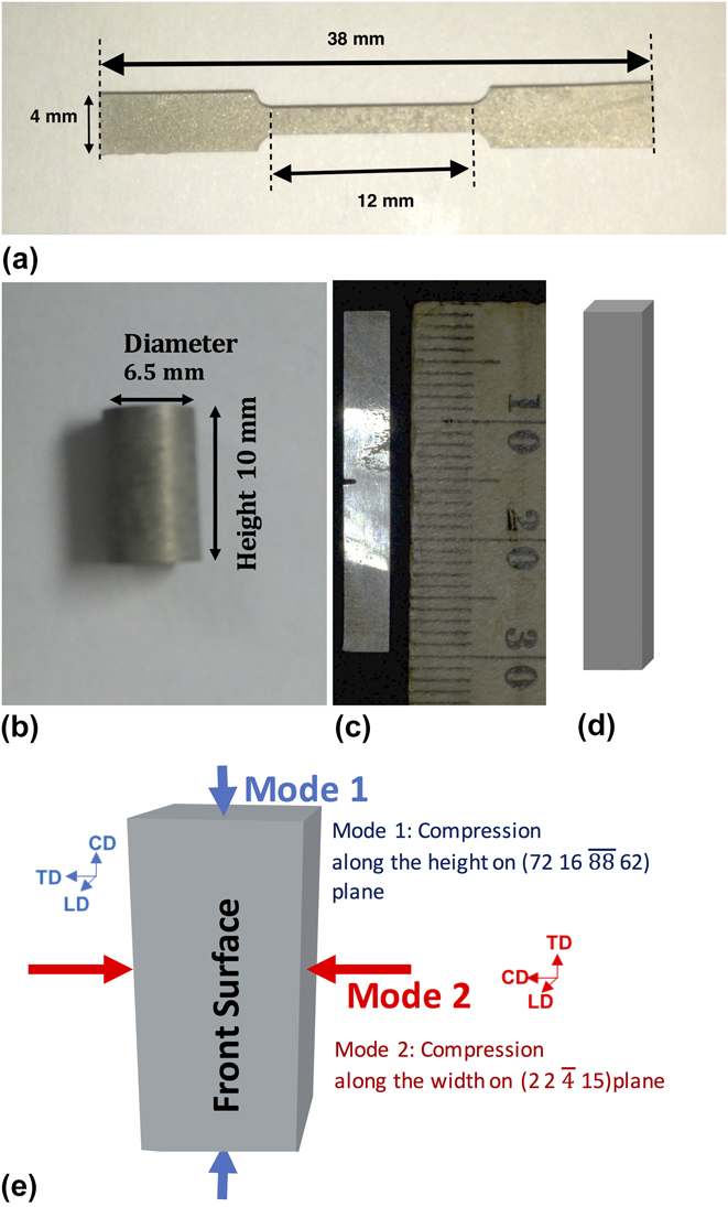
The single crystal and polycrystalline rods were cut in to dog-bone shaped test pieces [Fig. 1(a)] for tensile using an Accutex SPi 300 Electric Discharge Machining (EDM) set-up (AccuteX, Taichung City, Taiwan). The gauge length of the test pieces was maintained at 12 mm. The testing was carried out at the Cincinnati Testing Labs using a Sintec 30D-testing frame (Test Resources Inc., Shakopee, Minnesota). The crosshead extension rate for the tensile test was maintained at 1 mm/min.
Specimens cut in Accutex SPi-300 EDM Wire-Cut System; (a) Tensile Test specimen; (b) Compression Test Specimen; (c) Izod testing plate with a 1 mm notch in the center; (d) Bend Test Specimen; and (e) Schematic of compression testing along two orthogonal direction.

During the tensile test, it was observed that the single crystal specimen failed at a lower stress than the polycrystalline specimen. Hence, a cold worked sample was also tested using the same parameters. The cold working was done by compressing the sample laterally in a hydraulic press under a load of 1 ton. This operation provided 12% cold work, calculated based on the change of the dimension after compressing. The micro hardness of the cold worked specimens was measured with a knoops indenter (50 gm load) and about 100% increase in hardness was observed.
B. Compression testing
Compression testing was performed on single crystal and polycrystalline samples at the North Carolina A&T State University. An Instron mechanical testing system (Instron, Norwood, Massachusetts) was used to test the samples. The samples were EDM wire-cut at UC to obtain cylinders 6.35 mm in diameter and about 10 mm in height [Fig. 1(b)]. The displacement was measured using an extensometer. The samples included an as-received polycrystalline sample to obtain a comparison between the different single crystal samples and polycrystalline magnesium. The polycrystalline magnesium blocks were compressed at a rate of 0.2 mm/min, while the single-crystal magnesium blocks were compressed at a rate of 0.1 mm/min.
C. Izod testing
The impact toughness of the single crystal and polycrystalline Mg samples was explored at the Cincinnati Testing Labs. The equipment used was a Tinius Olsen Izod testing machine (Tinius Olsen USA, Horsham, Pennsylvania). A magnesium single crystal rod and a polycrystalline Mg rod were cut in rectangular plate geometry by the EDM system. Both plates had dimensions of 30 × 4 × 2 mm. A 1 mm notch was also wire EDM machined at the center of the specimens shown in Fig. 1(c).
D. Three-point bend test
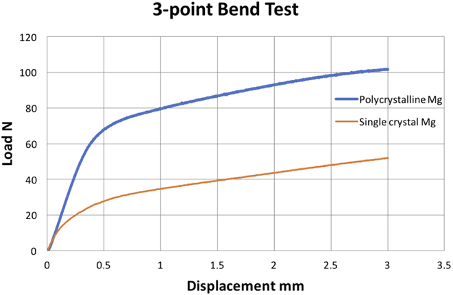
The bending and shear behavior of the Mg single crystal vis-à-vis polycrystalline Mg were observed by subjecting both materials to a 3-point bend test. The samples were EDM wire-cut as rectangular plates (30 × 4 × 2 mm), as shown in Fig. 1(d). The cross-head speed for the 3-point bend test was maintained at 0.5 mm/min.
E. Compression testing along two orthogonal directions
One of the ways to study the deformation mechanism in single crystal Mg is to apply compressive load on a single crystal block along two orthogonal directions thus obtaining low plastic strain. The application of load would activate the slip and twinning behavior, and evidence/traces of these microstructural phenomena can be observed on the front surface. A schematic of the testing is displayed in Fig. 1(e).
1. Precompression
Single crystals, 4 mm (l) × 4 mm (b) × 8 mm (h) blocks, were EDM wire-cut from a single-crystal Mg rod (10 mm diameter × 50 mm height). All sides of the blocks were polished to a 5-μm finish using Struers ‘4000’ grade SiC grit paper. The exact orientation of the Mg single crystal blocks and the planes on which the two modes of compression are determined using XRD pole figure analysis (Bruker Discover D8 system, Bruker AXS Inc., Madison, Wisconsin) are indicated in Fig. 1(e).
2. Compression testing
The compression testing was carried out in an Instron mechanical testing frame with electro-mechanical motion control and a 500 N load cell. For Ref. Reference Kirkland3, directions were defined for the blocks, i.e., Compression Direction (CD), Longitudinal Direction (LD), and Transverse Direction (TD). The blocks were compressed slightly up to 4 and 8% strain along the height (mode 1) and the width (mode 2) of the samples. In all cases, force was applied on the surfaces orthogonal to the polished surface leaving it untouched, as displayed in Fig. 1(e). In mode 1, the basal plane was found to be tilted at an angle of 68° from the plane of loading while in mode 2, the basal plane was found to be around 24° from the plane of loading.
3. Post-compression
The compressed blocks were polished on all sides under gentle load (100 gm) using an Allied Tech MultiPrep polishing system after compression to remove any deformation layer that may occur during the pre-compression polishing process. This was done using a 9-μm diamond polishing film in the distilled water media. The front surface of each block was further polished to a 1-μm level finish. Further, the XRD pole figure analysis was performed on the loading planes of the single crystal blocks to verify the orientations and to study the deformation behavior. Subsequently EBSD was also carried on the polished surfaces of the uncompressed and compressed single crystal blocks in an FEI Quanta 3D FEG SEM (FEI, Hillsboro, Oregon) at the North Carolina State University to observe the various deformation mechanisms during compression testing.
The EBSD and XRD pole figure data was analyzed in ‘Matlab’ using a Mtex tool kit. Reference Bachmann, Hielscher, Johnson and Mainprice23 Euler color orientation maps were obtained from the EBSD data. Similarly, Orientation Distribution Functions (ODFs) and Inverse Pole Figures (IPFs) were also plotted for both EBSD and XRD pole figures.
III. RESULTS
A. Tensile testing
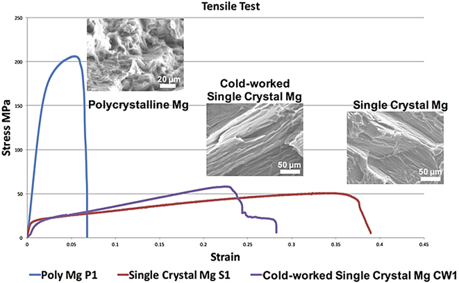
The obtained curves for tensile test 1 are shown in Fig. 2. The fracture surfaces after testing observed in the FEI XL30 Environmental SEM (FEI, Hillsboro, Oregon) and the Hitachi TM3000 Electron Microscope (Hitachi America, Ltd., Terrytown, New York) and are displayed as inset images in Fig. 2.
Stress–Strain curves for tensile test. The extension rate was maintained at 1 mm/min. Cold work performed by applying 1 Ton load perpendicular to the axis of the crystal rod. This corresponds to 12% of cold work. Insets show the SEM images of the fractured surface of the specimens from the tensile test.
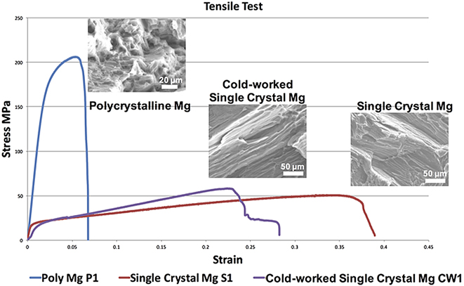
High ductility and superplastic tendency was revealed when conducting tensile tests on single crystal samples (Fig. 2). In our previous publication, we had reported plastic deformation up to 60% strain. Reference Salunke, Joshi, Chaswal, Zhang, Rosenbaum, Dowling, Decker and Shanov22 Despite their low tensile strength (∼50 MPa), they exhibit high plastic deformation indicating multiple twinning and slip-induced inhibition of strain localization and potential superplastic tendencies.
B. Compression testing
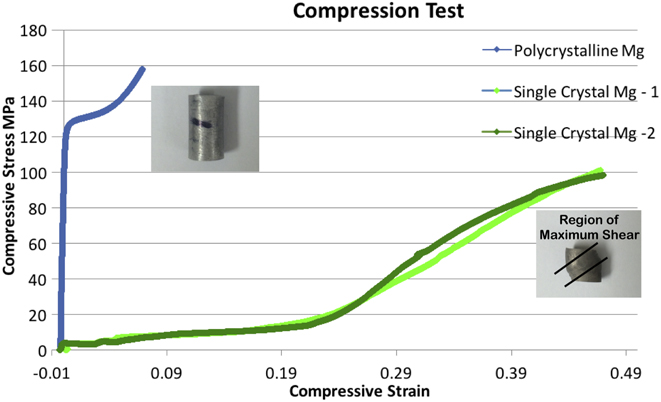
The compression test results of polycrystalline and single crystal magnesium samples are shown in Fig. 3. The samples were loaded up to a maximum load of 5000 N or a compression of 3.5 mm whichever was reached first.
Compression testing results for polycrystalline Mg and single crystal Mg specimens. The inset optical pictures show the blocks after the compression test was completed.

C. Izod testing
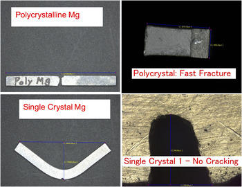
The Izod test results are displayed in Fig. 4. The polycrystalline Mg specimen fractured during the test and is marked by a flat rough fracture surface. The single crystal Mg samples show a sharp bend in the notched area. No fracture or cracks were observed for the single crystal in the region around the notch. More energy may be needed to initiate crack propagation in the single crystal specimen.
Optical pictures of Izod test samples after the impact was applied on them.

D. Three-point bend test
The bending test curves are represented in Fig. 5. The single crystal Mg specimen is less rigid and requires lesser load to attain comparable bending.
Preliminary test results for the 3-point bend tests.

During the mechanical testing, the Mg single crystal was found to have much lower yield strength, which points to an orientation more favorable for yielding. The single crystal also showed extraordinary ductility achieving up to 40% strain at room temperature. Such high plasticity is unusual in metals at room temperatures and may occur due to multiple twinning and slip-induced inhibition of strain localization. Super plasticity has often been seen in ultra-fine grained metallic alloys, but its presence in single crystals of Mg has also been observed and could be useful for some biomedical applications. Reference Nieh, Wadsworth and Sherby24,Reference Schmid and Boas25
1. Compression testing along two orthogonal directions
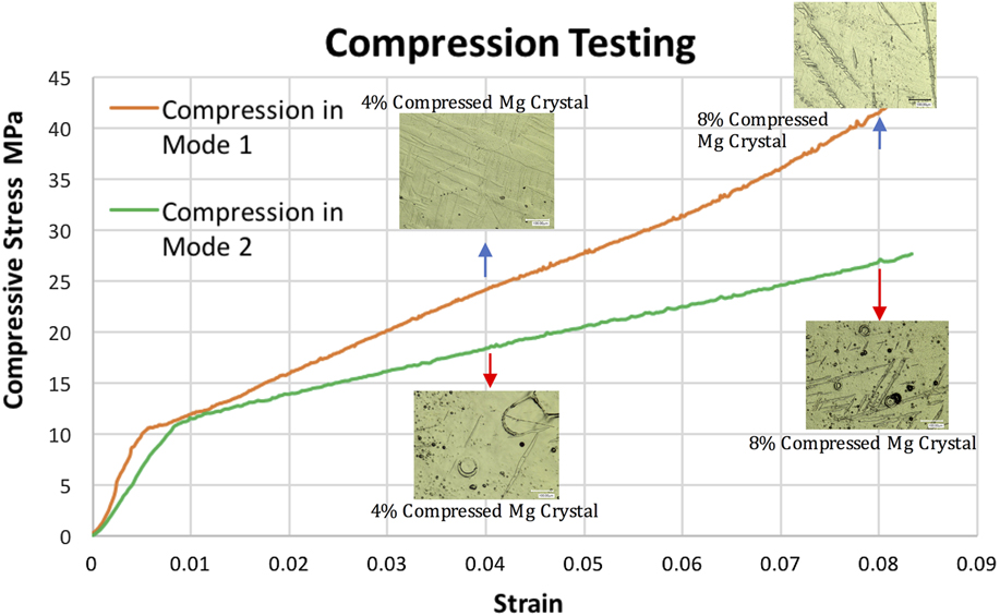
The stress–strain curves from the 2-directional compression tests are shown in Fig. 6. The orientation in Mode 1 has higher stiffness (Approximate Elastic Modulus = 2.248 GPa based on stress–strain curve) than the corresponding stress in Mode 2 (Approximate Elastic Modulus = 1.415 GPa based on stress strain curve). The following observations could be made from the optical images in Fig. 6.
Stress–strain curves from compression testing in Modes 1 and 2 with optical images of the compressed Mg single crystal blocks taken from their front surfaces.

2. Mode 1
-
(i) Extensive twinning is observed on the polished surfaces after compression.
-
(ii) The twinning appears to be along multiple directions.
-
(iii) After 8%, compressive deformation long twinned sections running along the CD of the single-crystal block occurred.
3. Mode 2
-
(i) Considerable twinning is observed along at least two directions.
-
(ii) The amount of twining due to compression in mode 2 appears to be less than that occurring during compression in mode 1.
-
(iii) Unlike Mode 1, long twinned sections running along the CD are not observed after 8% compressive deformation in mode 2.
E. XRD pole figures
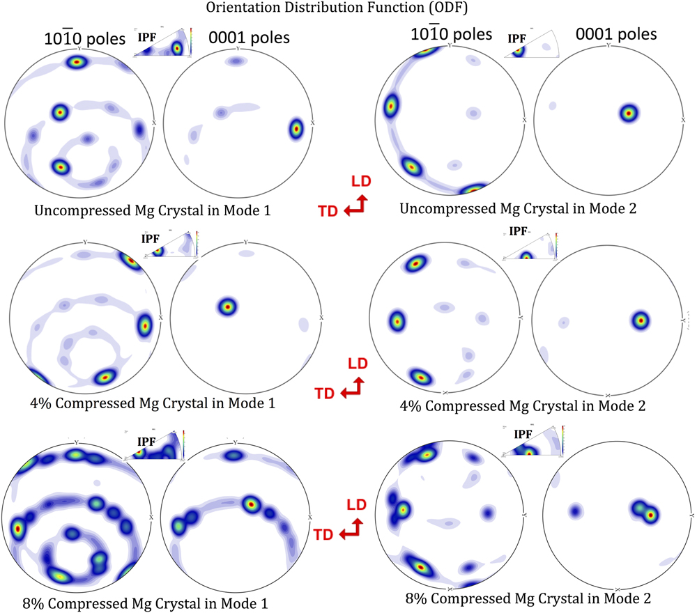
Pole figures were obtained from uncompressed and compressed Mg single crystals on the CD. The ODF and IPF images are shown in Fig. 7. The IPF for uncompressed specimen in the CD for Mode 1 reveals that the loading direction is normal to the (72 16
 $\overline {88}$
62) plane. The loading direction for Mode 2 compression was normal to the (2 2
 $\bar{4}$
15) plane. One can conclude the following studying the obtained pole figures in the both Modes of compression:
XRD pole figures for uncompressed and compressed Mg single crystal blocks. TD corresponds to ‘Tranverse Direction’ and LD corresponds to ‘Longitudinal Direction’ of the tested block.

1. Pole figures for samples compressed in Mode 1
-
(i) After 4% compression, significant amount of the crystal seems to have twinned.
-
(ii) After 8% compression in Mode 1, the pole figure shows considerable texture modification which could include primarily twinning as well as some recrystallization.
2. Pole figures for samples compressed in Mode 2
-
(i) The CD in Mode 2 is perpendicular to the plane (2 2
 $\bar{4}$
15).
-
(ii) After 4% compression in Mode 2, the primary orientation has reoriented slightly. Additional poles representing twinning are observed.
-
(iii) After 8% compression in Mode 2, there appears to be development indicative of texture modification. However, this modification is still less extensive than Mode 1.

F. Electron back scattered diffraction (EBSD)
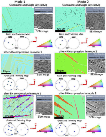
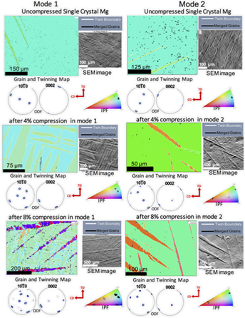
The EBSD analysis was done on the polished front surface or in the longitudinal direction (LD) of the single crystal blocks. Colored mapped images were obtained through the inverse pole figure Z for both compression modes as shown in Fig. 8. Corresponding pole figures were also obtained for the polished surfaces, and the ODFs of basal {0001} and prismatic {10
 $\bar{1}$
0} are shown as inset in Fig. 8.
EBSD color-orientation mapping images and ODF images for uncompressed and compressed single crystal Mg blocks. Twin boundaries are marked by white lines, whereas grain boundaries are marked by black lines on the EBSD images. The SEM images are shown next to the corresponding EBSD image. Color IPF images indicate the concentration of orientations on the front surface of the Mg crystal blocks.

1. Single Crystal Mg before compression
Before compression, the EBSD pattern of single-crystal magnesium shows roughly a single greenish hue, which is dominant. The color orientation legend below reveals that the polished surface is closer to the prismatic planes. Secondary spots corresponding to other orientations appear because of the surface damage during polishing.
2. Single Crystal Mg after compression
After compression, the EBSD patterns show distinct elongated green colored bands. These regions are twinned parts of the Single Crystal lattice which are now oriented differently than the untwined parts of the lattice. The presence of twinning along multiple orientations even at lower compression strains such as 4% indicates that deformation twinning contributes significantly to the plastic deformation of Mg single crystals. Further compression to 8% strain in Mode 1 results in appearing of larger twin bands and newer twin variants (indicated by red-blue bands) over the greenish-blueish lamellar structure seen at a lower strain. There is also secondary twinning which appears as distinct dark blue regions within the red twin bands. Closer observation of these regions shows that the whole texture has been considerably changed by profuse twinning to form distinct sub-regions with multiple orientations. This development may be the precursor to further recrystallization, resulting in a polycrystalline microstructure.
In comparison, during Mode 2 compression, the extent of twinning after 4% strain is considerably less than that observed in Mode 1 compression. After 8% compression (Mode 2), the amount of twinned region has increased. However, there is no profuse twining and texture modification, as was observed in Mode 1 compression. The detection of twin and grain boundaries was done using the EBSD software. The obtained images may not represent all the modifications in the single-crystal substructure and is limited by sample preparation. Accordingly, the interpretation presented here is of a qualitative nature.
IV. DISCUSSIONS
The initial mechanical testing on the magnesium single crystals has shown high ductility. The tensile tests revealed up to 40% strain (under the given test conditions and sample geometry) at room temperature. The initial compression test showed that the single crystal Mg blocks achieved more than 40% strain at much lower stress levels as compared to untreated commercial polycrystalline magnesium. The 3-point bend tests also showed that Mg single crystals could exhibit equivalent bending at nearly half the load required to bend a similar polycrystalline Mg specimen. In the Izod impact test, the Mg single crystal specimens absorbed the impact force by bending in contrast to the polycrystalline plate which fractured almost instantaneously. The absence of grain boundaries minimizes the obstruction to slip. However, at room temperature, the dominant planar basal slip allows only 3 close-packed directions i.e., 〈11
 $\bar{2}$
0〉, 〈1
 $\bar{2}$
10〉 and 〈
 $\bar{2}$
110〉 which are inadequate to account for the complete 3-dimensional deformation and shape change, as observed at such high strains. Hence alternate modes of deformation using non close-packed slip or twinning are essential during enhanced plastic deformation.
It is known that the deformation mechanisms of Mg single crystals are highly orientation-dependent due to the strong anisotropic nature of the single crystal. The principal modes of deformation in Mg like in other HCP metals are slip and twinning. Slip occurs on the (0001) basal plane along the 11
 $\bar{2}$
0 close-packed directions.
Reference Hayden, Moffatt and Wulff26,Reference Christian and Mahajan27
Pyramidal slip (c + a slip on 10
 $\bar{1}$
1 pyramidal planes) can occur, but it requires a higher critical resolved shear stress (CRSS) than the basal slip and hence it is often seen at higher than ambient temperatures. The extension twinning {10
 $\bar{1}$
2} 〈10
 $\bar{1}$
1〉 has a critical resolved shear stress (∼6–7 MPa) close to that of basal slip (∼1 MPa).
Reference Kelley and Hosford9,Reference Chapuis and Driver15
Therefore, extension twinning is an important mode for accommodating strain along the c-axis.
Reference Yu, Jiang and Wang28
However, the localized shear associated with twinning often restricts the ductility of the Mg alloys.
Reference Yu, Jiang and Wang28
In addition to providing an important strain accommodation mechanism out of the basal plane for needed general deformation, twinning strongly modifies the texture, the anisotropy, and the hardening response by interacting with dislocations in complex ways.
Reference Reed-Hill and Abbaschian29
The other common twin type in magnesium is the {10
 $\bar{1}$
1} contraction twin.
Reference Yoo30
However, the high CRSS for the contraction twinning makes it highly unlikely at stress levels achieved in our compression tests.
Reference Chapuis and Driver15
The additional compression testing and the subsequent analyses highlighted the various microstructural changes which account for deformation in magnesium single crystals. The XRD pole figure analysis shows that the basal plane pole is tilted at an angle of 68° [Schmid Factor (SF) = 0.35] from the direction of compression in Mode 1. After 4% compression in Mode 1, twinning has modified much of the crystal such that in the twinned regions, the 0001-basal plane has rotated to reduce its tilt to 24° from the compression axis. The modified SF of around 0.37 for the twinned regions is slightly more favorable to activate the basal slip in agreement with the literature
Reference Chapuis and Driver15
and for the nominal stresses of around 20 MPa as seen in Fig. 6. Two twinning variants are represented in the microstructure as dense lamellar green bands aligned in two nearly perpendicular directions as seen in the EBSD images. Both the basal slip and {10
 $\bar{1}$
2} twining are favorable modes since they have much lower CRSS values at ambient temperature. As the Mg single crystal is compressed further in Mode 1, two more variants of the extension twinning appear at 8% strain. This twinning is marked as thicker red-blue bands in the EBSD color-maps which run continuously along the direction of compression. The initial twinning variants accompanied by the slip have resulted in a buildup of stress within the crystal causing additional twinning variants being activated. These twin bands interact with the previously formed twins to create a more complex microstructure within the twinned region. The interaction between different twinning bands and the potential build up stress in the twinned zones result in reorientation of small regions along the interface of the different twin modes. This phenomenon can be marked as the beginning of dynamic recrystallization.
In contrast to Mode 1, the beginning of Mode 2 is closer to compression on the basal plane. The basal plane pole is tilted at around 24° from the compression axis. This orientation is moderately favorable (SF = 0.37) for the basal slip. Under compressive load, the basal plane realigns to a more favorable tilt of 36° (SF = 0.47) from the compression axis. The EBSD and XRD pole figures indicate that two modes of the 10
 $\bar{1}$
2 extension twinning are activated during compression. The amount of twinning is considerably less than that found in Mode 1 since the orientation is more favorable for the basal slip, and a greater proportion of the strain is accommodated through the slip. As the crystal is compressed beyond 4%, the basal slip accommodates a smaller proportion of the strain, and extension twinning becomes more widespread across the metal matrix. However, even at 8% compressive strain, twinning is not as profuse as seen in Mode 1. Recrystallization by way of formation of low-angle grain boundaries is much less prominent than in the equivalent Mode-1 compressed crystals. Minor secondary twinning within the primary twins can be observed after 8% strain in Mode 2 (Fig. S1).
The difference in the strain behavior during the two different modes in compression can be explained in terms of the crystal response to compressive stress. In Mode 1, the crystal cannot easily realign itself more favorably for the basal slip. However, the twinning modes are still favorably oriented and twinning accommodates a greater proportion of the strain. Even with the presence of twinning variants in Mode 1, it is observed from the stress–strain curves that the stress needed to be applied in Mode 1 is greater than that in Mode 2 due to less favorable basal slip orientation. The twin–twin interaction and stress concentration within the twinned regions cause the formation of reoriented regions with high defect density, which can be marked as the initiation of possible dynamic recrystallization. In Mode 2, the ability of the crystal to realign itself more favorably toward the basal slip reduces the stress needed for the equivalent strain. Since the stress is lower and twinning is not as widespread, recrystallization is minimal.
The contrasting response of the magnesium single crystals to the change in orientation of loading provides the opportunity for modifying the mechanical properties of the crystal by changing the orientation without the need of adding alloying elements. A comparison between the properties of the bone with Mg single crystals and some commonly used magnesium AZ alloys (Fig. S2) reveals that high-purity magnesium crystals, although lesser in strength, have a much higher ductility. The latter quality is useful for implants located in regions experiencing significant motion and interplay between bones and tissues such as: the Anterior Cruciate Ligament ring and craniofacial devices. Reference Zheng31–33
V. CONCLUSIONS
High ductility (∼40%) was observed for undeformed Mg single crystals under the test conditions. This value is reduced down to ∼30% for cold-worked single crystals of the same orientation but still remains greater than commercial polycrystalline Mg samples (∼7%). Energy absorption capacity is higher for both cold-worked and undeformed Mg single crystals compared to the polycrystalline Mg, as estimated from the area under the tensile curve. Cold work up to 12% increases the strength by around 20% without significantly reducing the toughness of the single crystal. The conducted impact testing demonstrated that the magnesium single crystal is highly ductile, and the impact energy is absorbed largely by twinning and slip. However, the polycrystalline samples revealed mostly a brittle behavior and fractured easily under impact. During room temperature compressive tests, incipient recrystallization was observed at strains as low as 8% in pure Mg single crystals. This recrystallization was found to initiate at the twin–twin interface, as proved by the EBSD imaging. Pole figure analysis indicates that the local reorientation of crystal regions occurs during uniaxial compression and straining. Out of two almost orthogonal modes of compressive loading conducted on the single crystal, Mode 1 compression is less amenable to slip compared to Mode 2. A greater degree of twinning and recrystallization has been observed in Mode 1 compared to Mode 2, indicating that the crystal rotation through twining is occurring in a way to make the crystal more responsive for a slip. The proposed hypothesis is qualitative and will need further experimental validation and quantification.
Supplementary Material
To view supplementary material for this article, please visit https://doi.org/10.1557/jmr.2017.419.
ACKNOWLEDGMENT
This work has been funded by NSF through the ERC grant NSF-EEC 0812348 called “Revolutionizing Metallic Biomaterials” and the authors are thankful for the provided financial support.