I. INTRODUCTION
12Cr2Mo1R(H) steel is a kind of Cr–Mo steel and is mainly composed of bainite after being normalized and tempered at temperatures higher than 680 °C, which is suitable to make hot-wall hydrogenation reactors due to excellent mechanical properties and hydrogen embrittlement (HE) resistance of the structure. However, long exposure to the harsh environment of high-pressure hydrogen can still induce the adsorption of hydrogen atoms. Ultimately, the hydrogen uptake would severely damage the mechanical properties of the steel with surface hydrogen-induced cracks (HICs).Reference Mohtadi-Bonab, Karimdadashi, Eskandari and Szpunar1–Reference Magudeeswaran, Balasubramaniarr, Madhusudhan Reddy and Balasubramanian3 The interactions between hydrogen and steel have been extensively studied by researchers. Several convincing theories about HE, such as pressure theory, hydrogen enhanced decohesion,Reference Fu and Painter5,Reference Takahashi, Kondo, Asano, Arai, Higuchi, Yamamoto, Muto and Tanaka6 adsorption induced dislocation emission,Reference Bond, Robertson and Birnbaum7 and hydrogen enhanced localized plasticity,Reference Hassan Sk, Overfelt and Abdullah8 have been proposed as well. All these theories emphasize direct effects of hydrogen itself on HE and pressure theory is the most accepted one.Reference Griesche, Dabah, Kannengiesser, Kardjilov, Hilger and Manke9 In addition, other researchers attribute the HE to vacancies rather than hydrogen itself which is thought to enhance the creation of strain-induced vacancies during plastic deformation.Reference Takai, Shoda, Suzuki and Nagumo10 The corresponding mechanisms of HE remain under discussion and have not been fully understood so far.
To improve the HE resistance, several studies have been focused on the effects of microstructures on HE. It is reported that the as-quenched martensite exhibits the lowest HE resistance, while tempered martensite and bainite have the strongest, with the performances of pearlitic structures in between.Reference Depover, Van den Eeckhout and Verbeken11,Reference Michler, Marchi, Berreth, Naumann, Mishra and Kubic12 Koyama et al.Reference Koyama, Okazaki, Sawaguchi and Tsuzaki13 found that metastable ε-martensite, serving as the nucleus of α′-martensite, is highly susceptible to HE because it acts as initiation sites of cracks. Stable ε-martensite easily produces stress concentration to assist HE. The γ/ε interface not only acts as crack initiation sites but also inhibits crack propagation. DepoverReference Depover, Wallaert and Verbeken14 pointed out that the diffusion coefficient of hydrogen in bainite is only in the order of 10−6 cm2/s. The actual diffusion distance of hydrogen is too low to significantly affect the HE susceptibility. Moreover, DunneReference Dunne, Hejazi, Saleh, Haq, Calka and Pereloma15 reported that the high density of lath structure in bainite ferrite forms easy paths for hydrogen diffusion and the dislocations act as weak and reversible traps for hydrogen atoms. Consequently, the absorbed hydrogen is more uniformly distributed, delaying the accumulation of hydrogen at sites of stress concentration to the critical content required to induce cracking. The above-mentioned study is helpful to reveal the reason for good hydrogen resistance of the bainitic structure. However, the interaction between hydrogen and the 12Cr2Mo1R(H) steel with bainite structure have not yet been fully studied so far, which requires further investigation for better application of the steel.
Additionally, the effect of different element contents (especially carbon, manganese, and chromium) and thermomechanical treatment on the material–hydrogen interaction has also been studied widely. DepoverReference Depover, Van den Eeckhout and Verbeken11 found that increasing carbon content of a bainitic microstructure results in increased HE due to the larger amount of diffusible hydrogen through studying the impact of hydrogen on the ductility loss of a bainitic Fe–C alloys. Dunne et al.Reference Dunne, Hejazi, Saleh, Haq, Calka and Pereloma15 studied the effect of microstructure on hydrogen-induced cold cracking (HICC) and blistering. They found that the banded ferrite-pearlite structure is susceptible to HICC and easy to develop surface blisters in the highest extent, while the bainitic ferrite structure did not blister even after the maximum period of hydrogen charging. HuiReference Hui, Zhang, Zhao, Shao, Wang, Sun and Yu16 studied the influence of cold deformation and annealing on HE of bainitic steel. It is pointed out that the cold deformation significantly enhances its susceptibility to HE, which is mainly attributed to a remarkable increase of diffusible hydrogen absorption in the deformed material and the occurrence of more strain-induced martensite. They also reported that annealing after cold deformation is an effective way to improve HE resistance. Moreover, the HE susceptibility decreases significantly if the annealing temperature exceeds 200 °C. It is attributed to the release of hydrogen, recovery of the cold deformed microstructure, especially decomposition of strain-induced martensite.
It is well known that grain boundaries, especially coincidence site lattice (CSL) boundaries, play a pivotal role in HIC crack propagation. Arafin et al.Reference Arafin and Szpunar17 investigated intergranular stress corrosion cracking of a pipeline steel and found that low angle and CSL boundaries, mainly ∑11 and ∑13 band, probably ∑5, are crack-resistant, while the CSL boundaries beyond ∑13b and the random high-angle boundaries are prone to cracking. However, there is no scientific consensus on the effect of CSL boundaries for different materials. Gertsman et al.Reference Gertsman and Bruemmer18 have analyzed the grain boundary (GB) character along intergranular stress corrosion cracks and at crack arrest points. They believed that only ∑3 boundaries have crack resistance. However, Mohtadi-BonabReference Mohtadi-Bonab, Eskandari, Rahman, Ouellet and Szpunar19 proposed that ∑3-type boundaries are high angle grain boundaries (HAGBs), which can increase the HIC susceptibility by providing propagation of intergranular cracks with easy paths. It was concluded that CSL boundaries of different metals should be evaluated separately.
Up to now, some explanations have been made for the HE of bainite steel, while the studies about the HIC propagation in bainitic steel are yet quite limited. This work aims to investigate the effects of hydrogen-charging conditions on HE and HIC cracks of bainitic steel. The type of CSL grain boundaries of 12Cr2Mo1R(H) steel and their effect on HIC cracks’ propagation will also be discussed. Electrolytic hydrogen charging in an acidic environment would be applied in the study as the environment of the hydrogen charging is harsher than that of the gas-purging one.Reference Mohtadi-Bonab, Karimdadashi, Eskandari and Szpunar1
II. EXPERIMENT
The 12Cr2Mo1R(H) steel was produced via oxygen converter smelting, followed by ladle furnace refining and vacuum degassing process (EAF + LF + VD). The main elemental contents of the steel include 0.145% C, 0.48% Mn, 2.415% Cr, 0.951% Mo, 0.12% Ni, and 0.124% Cu. The Vickers hardness of the steel is ∼213.00.
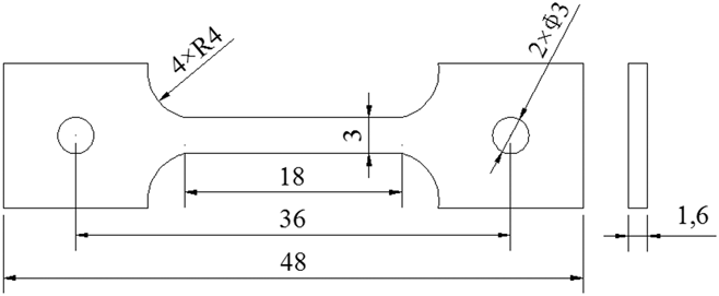
Samples for the tensile test were cut into the shape (shown in Fig. 1) by EDM cutting. Then they were ground with SiCs and paper up to 2000 meshes and polished with 2.5 μm diamond paste, as polished samples are more sensitive to hydrogen damage.Reference Pérez Escobar, Minambres, Duprez, Verbeken and Verhaege20 After that, the samples were etched with LePera reagent (1% solution of sodium pyrosulfite mixed with 4% solution of picric acid), before metallography observation in an optical microscope (OM) (AxioCamMRc 5, ZEISS, Oberkochen, Germany).
Geometry of the tensile sample (unit: mm).

Tensile tests were performed in air before and after 4 h of electrochemical hydrogen charging, with 15 mA/cm2 current density in 0.5 M sulfuric acid solution with 2 g/L ammonium thiocyanate. Strain rates at 5 × 10⁻³ s−1, 5 × 10⁻⁴ s−1, 5 × 10⁻⁵ s−1, and 5 × 10⁻⁶ s−1 were set to investigate their effects on HE susceptibility of 12Cr2Mo1R(H) steel. The hydrogen susceptibility of a sample was evaluated by the embrittlement index (EI)Reference Zhu, Zhang, Li and Jin21:
 $${\rm{EI}}\left( \% \right) = {{{\delta _{{\rm{air}}}} - {\delta _{{\rm{charge}}}}} \over {{\delta _{{\rm{air}}}}}} \times 100\% \quad .$$
The EI was defined as the decrease in elongation (δ%) after hydrogen precharging. The samples are more susceptible to HE when EI is closer to 1.
A field emission scanning electron microscope (FESEM; JSM-7001F, JEOL, Tokyo, Japan) was also utilized for fracture morphology analysis after tensile test. The phases of the specimens were identified by X-ray diffraction (XRD) with a Cu Kα1 radiation range of 20° < 2θ < 90°. HIC cracks of the fractured specimens were captured with field emission FEI Quanta FEG 250 SEM (Hillsboro, Oregon) equipped with an electron backscatter diffraction (EBSD) system, and software Channel 5 (Oxford, United Kingdom) was used to interpret the EBSD results.
III. RESULTS AND DISCUSSION
A. Microstructures
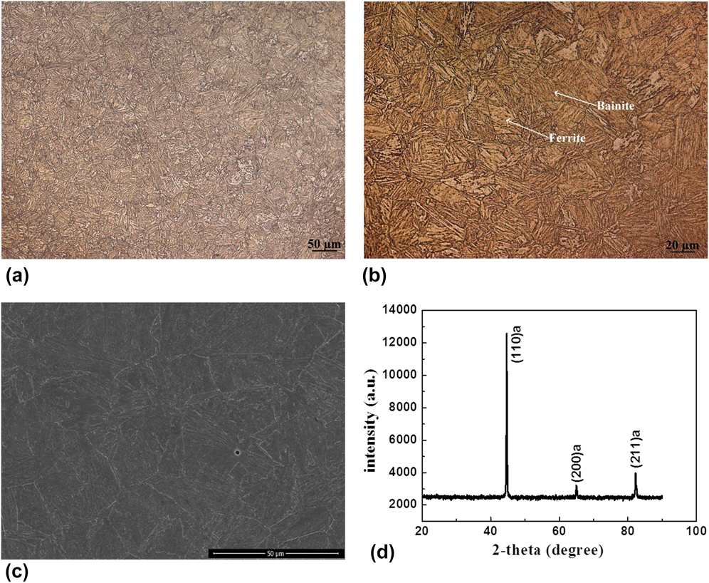
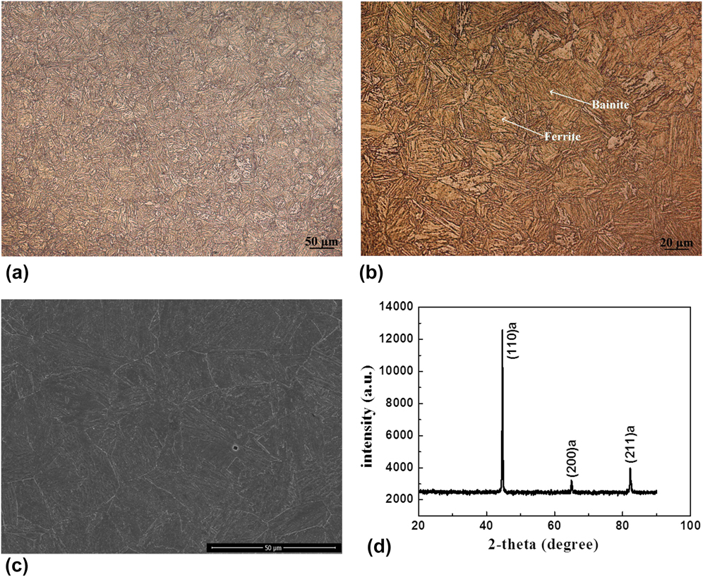
Figures 2(a)–2(c) show the metallographic structures of the 12Cr2Mo1R(H) steel, which is composed of 100% bainitic ferrite. Fine lath structure of bainitic ferrite was formed in previous austenite grains with a size of 20–60 μm. Figure 2(d) shows the XRD spectra of the untested samples. Three typical ferritic peaks α(110), α(200), and α(211) were presented, indicating high volume fraction of bainitic ferrite (almost 100 vol%). The result measured by XRD is consistent with above OM observation.
Metallography of 12Cr2Mo1R(H) steel taken, (a), (b) by OM, (c) by SEM, and (d) XRD spectra of the steel.
B. Tensile test
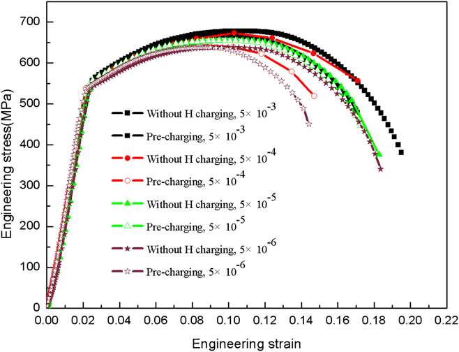
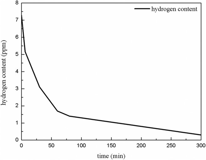
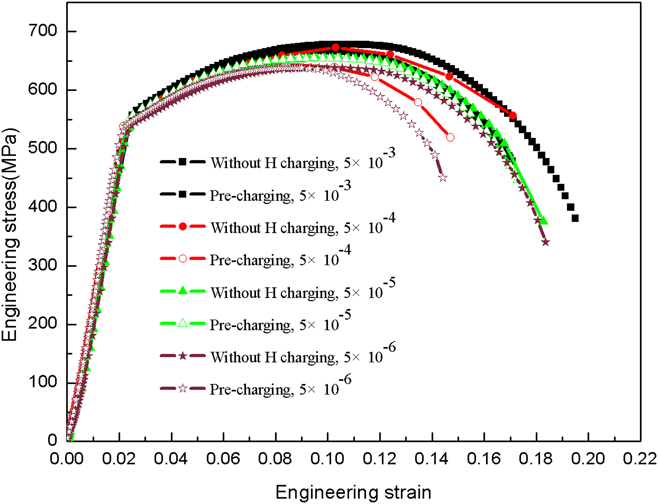
Figure 3 shows the engineering stress–strain curves of the uncharged and hydrogen precharged samples conducted at different strain rates. The results are summarized in Table I. The yield and ultimate tensile strength of the uncharged and precharged samples decreased with strain rates. No significant difference was found in yield and tensile strengths at different strain rates between uncharged or precharged samples. However, the elongation of the hydrogen precharged samples was much smaller than that of the uncharged samples even though it did not change much for uncharged or precharged samples, respectively, as shown in Table I. Several studies showed that HE sensitivity increases with the decrease of the strain rate because the rate of hydrogen enrichment cannot keep up with the sample deformation at high strain rates.Reference Depover, Wallaert and Verbeken14,Reference Depover, Pérez Escobar, Wallaert, Zermout and Verbeken22 It can be seen from Table I that the HE susceptibility increases and gradually reaches a relative stable level at the strain rate of 5 × 10⁻⁵ s−1 with the decrease of strain rates. Corresponding EI at the transient stable stage is about 20%. After hydrogen charging, the bainitic ferrite lath structure with high dislocation density exhibits high diffusible hydrogen and low residual hydrogen content. This indicates that the structure has a low density of irreversible trapping sites.Reference Depover, Wallaert and Verbeken14,Reference Saleh, Hejazi, Gazder, Dunne and Pereloma23 The concentration of hydrogen that diffused into the traps increased with the decrease of the strain rate, which increased the HE susceptibility. After the strain rate is less than 5 × 10⁻⁵ s−1, a certain amount of diffusible hydrogen desorbed from the reversible traps, as shown in Fig. 4, which reduced the content of diffusible hydrogen in samples. So the EI tended to be transient stable after both of them reached equilibration. The maximum EI of the precharged samples is about 20.00%, which belong to light hydrogen damage, indicating that the 12Cr2Mo1R(H) steel possesses good HE resistance.
Stress–strain curves of the uncharged and precharged samples tested at different strain rates.
Summary of the tensile tests conducted at different strain rates.

Curve of the hydrogen content with test time.

C. Fracture morphology
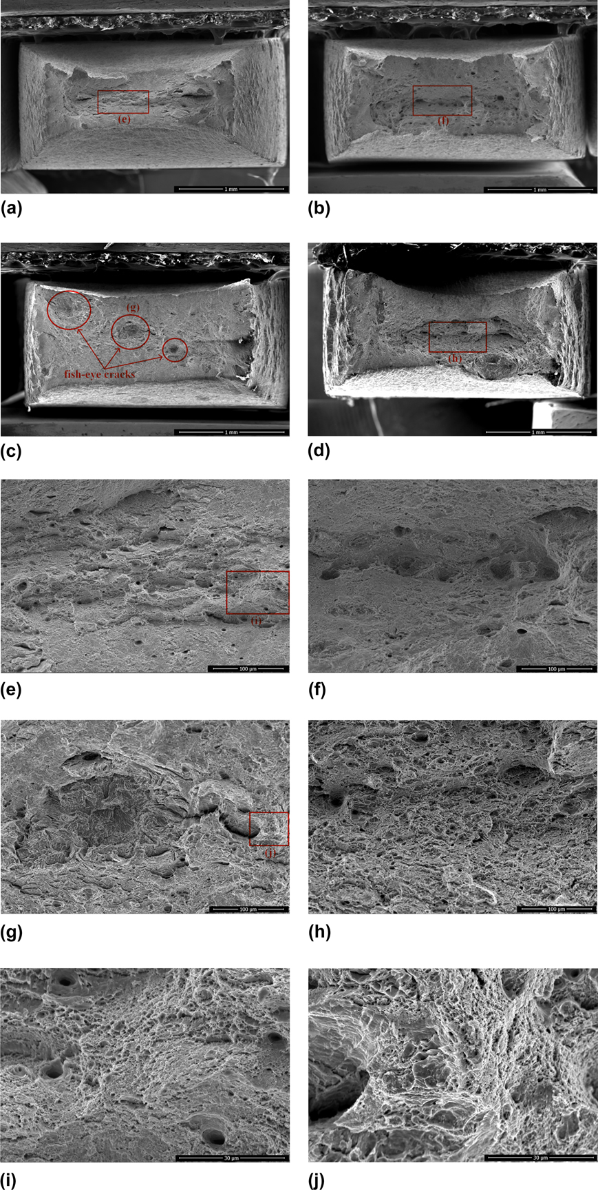
Figures 5(a), 5(e), and 5(i) show the fracture morphology of the uncharged sample tested at a strain rate of 5 × 10⁻⁴ s−1. Figure 5(a) exhibits a typical ductile fracture surface with obvious shear lip and necking. Both large and tiny secondary cracks along the transverse direction were observed. The fracture surface was covered by fine dimples and microvoids as illustrated in Figs. 5(e) and 5(i), which indicates the cavities or dropped inclusions in test samples.
SEM images of fractographies of (a), (e), and (i) uncharged sample tested at a strain rate of 5 × 10⁻⁴ s−1 and precharged sample conducted at different strain rates, (b), (f): 5 × 10⁻³ s−1, (c), (g), and (j): 5 × 10⁻⁴ s−1, (d), (h): 5 × 10⁻⁵ s−1.
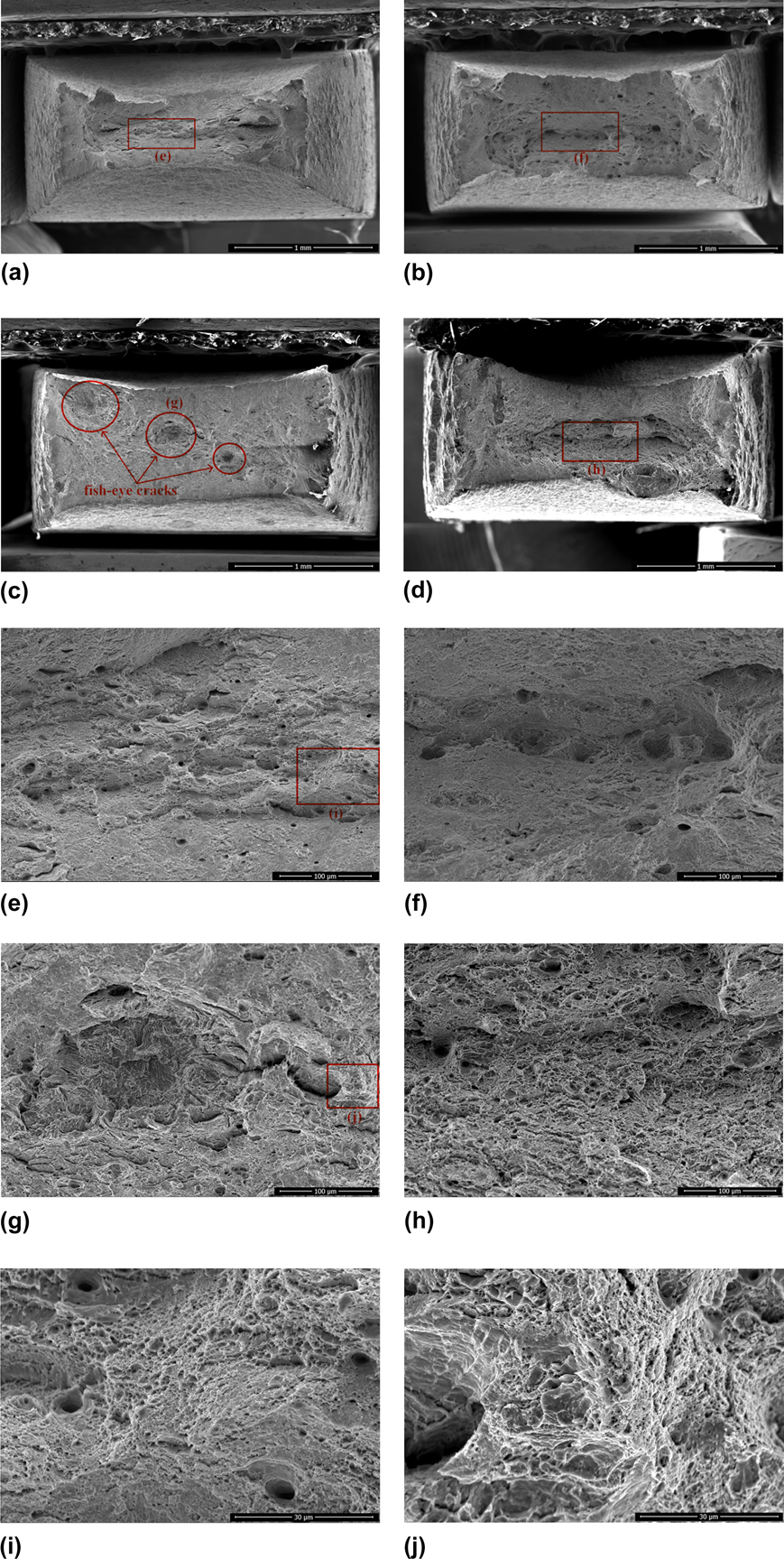
Figures 5(c), 5(g), and 5(j) present the fracture morphology of the precharged sample tested at a strain rate of 5 × 10⁻⁴ s−1. Figure 5(c) exhibits features of the brittle fracture surface as the necking phenomenon was hardly seen. However, three fish-eye cracks were discovered on the fracture surface, which is called flake and is one typical feature of HE. Figure 5(g) is the SEM image of the hydrogen flaking with obvious quasi-cleavage in high magnification. The cracks nucleated at the center of the flaking and the tear edges exhibited radical from center to outside. The flakes should be mainly evolved from the microvoids in the sample, which could be explained by combining the hydrogen pressure mechanism with the coalescence of the microvoid mechanism. During the hydrogen charging process, various defects, such as grain boundaries, microvoids, and inclusions, could serve as traps for hydrogen atom absorption, and the hydrogen atoms would diffuse to the high-stress areas such as microvoids and inclusions. These trapped hydrogen atoms would then combine into hydrogen molecules and generally form pressure. When the combined force of pressure and external stress reaches the yield strength of the steel, partial plastic deformation occurs. When the pressure exceeds their interatomic force, the crack nucleated and the hydrogen pressure reduced. With the hydrogen atoms gathered continuously, the pressure increased again and the cracks propagated outward. As a result, hydrogen flake formed at last. Some quasi-cleavage cracks around the flakes were found to propagate along the transverse direction, which could attribute to the microcrack nucleating and propagating at the slip band intersections. The quasi-cleavage phenomenon indicates the formation of intense slip bands and the possibility of localized enhancement of plasticity.Reference Hassan Sk, Overfelt and Abdullah8 Figure 5(j) shows that the part without flakes is still covered by dimples.
Figures 5(b) and 5(f) show the fractography of the precharged sample tested at a strain rate of 5 × 10⁻³ s−1. It can be observed that lots of small and deep hydrogen flakes locate on the fracture surface. The fractography of the precharged sample tested at a strain rate of 5 × 10⁻⁵ s−1 is shown in Figs. 5(d) and 5(h). One large flake was observed at the edge of the fracture surface with high hydrogen concentration.
It can be concluded from the observation that the sample HE is mainly characterized by hydrogen flaking damage. Hydrogen would be allocated in lattice, grain boundaries and irreversible traps such as cavities and inclusions during electrolytic charging. At high strain rate (5 × 10⁻³ s−1), dislocations would break the chain of hydrogen atoms and move on their own. Due to its low diffusion coefficient, only a small amount of hydrogen around the defects can be absorbed. The quasi-cleavage propagation is limited, forming small and deep flakes. When the strain rate is low (5 × 10⁻⁴ s−1), more and more hydrogen would diffuse to the cracks. Dislocations would act as easy paths for the hydrogen diffusion and absorb the hydrogen atoms from reversible traps during their movement and dump them to the irreversible traps or crack tips. As a result, the area of the quasi-cleavage increases and large flakes are formed. If the strain rate is extremely low (5 × 10⁻⁵ s−1), some of the hydrogen atoms would release from the reversible trap sites, which reduced the total diffusible hydrogen concentration. When both of them reached equilibrium, the HE susceptibility tended to reach transient stable.
D. HIC propagation
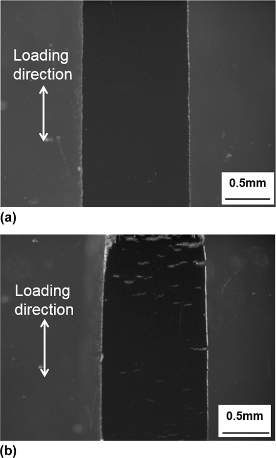
Figures 6(a) and 6(b) represent the lateral morphology of the uncharged and precharged sample tested at a strain rate of 5 × 10⁻⁴ s−1 by using a stereo microscope (Stemi 508, ZEISS), respectively. Large amounts of secondary cracks at the side surface of the precharged sample were observed, while no cracks exist for the uncharged sample. This indicated that the secondary cracks of the precharged sample were HIC cracks. Most of the HIC cracks are perpendicular to the loading direction. The phenomenon would be caused by the following reason. Hydrogen atoms diffuse into the steel from the surface with a higher hydrogen concentration. The absorbed hydrogen could promote the emission and movement of dislocations, which increases the localized plastic deformation. The stored energy will be dumped into this localized zone, accelerating damage accumulation. When the concentration of localized hydrogen reaches critical point under applied stress, the cracks would initiate early at the sample surface. In other words, high concentration of localized hydrogen under loaded stress lead to the generation of secondary cracks on the lateral of the precharged sample. As for the uncharged steel samples with higher ductility, a larger amount of energy would be absorbed by plastic deformation and necking. The ductile cracking would therefore occur after microvoids formation and serious deformation of the steel sample.Reference Laureys, Depover, Petrov and Verbeken24,Reference Xie, Li, Meng, Wang, Gumbsch, Sun, Ma, Ju and Shan25
The lateral morphology of the (a) uncharged sample and (b) precharged sample, conducted at a strain rate of 5 × 10⁻⁴ s−1.

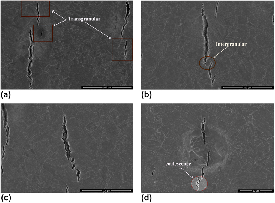
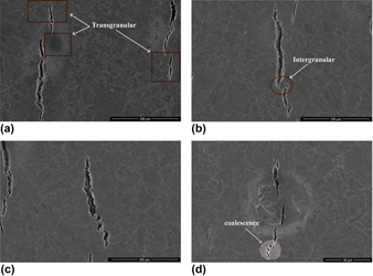
The HIC crack propagation is characterized in Fig. 7, both in intergranular and transgranular, and the latter was the predominant propagation mode. Most of the cracks propagate transgranularly through the lath bainitic ferrite with the rest diffusing along the lath boundaries. Besides, high strains of two adjacent and parallel HICs seem to have mutual influences on further propagation of each other. The crack tips interact and deflect toward each other, inducing coalescence and sometimes causing an ‘island’ covered with the cracks.Reference Laureys, Depover, Petrov and Verbeken26
HIC crack propagation: (a) transgranular mode; (b) intergranular mode and coalescence of crack tips; (c) and (d) coalescence and connection of crack tips.

E. EBSD results
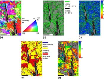
EBSD is used to study the HIC crack propagation. Figure 8(a) is the inverse pole figure (IPF) map of the HIC cracks. Figure 8(b) demonstrates the type of grain boundaries around the cracks. The grain boundaries with the misorientation angles of 1° < θ < 10° and θ > 10° were defined as low angle grain boundaries (LAGBs), and HAGBs, represented in green and black color, respectively. It was illustrated that the LAGBs mainly accumulated around the HIC cracks, showing the high dislocation density along the pathway of HIC crack propagation. Dislocation, one kind of hydrogen traps, can take enormous numbers of hydrogen atoms (about 104 times higher hydrogen atoms by diffusion) to the crack tips and promote the crack propagation. Figure 8(c) shows the kernel average misorientation (KAM) map around the HIC cracks, and the color represents misorientation values from low (blue) to high (red). The KAM map is mainly used to assess the degree of the local plastic deformation and the distribution of strain field. It shows the average misorientation between a given point and its neighbors inside the same grain, and the value is less than 5°.Reference Mohtadi-Bonab, Eskandari, Rahman, Ouellet and Szpunar19 The result points out that the high strain concentration in the regions around the HIC cracks tips. High strain concentration is usually thought to induce hydrogen diffusion to accumulate at the HIC crack tips.
EBSD analytical results around HIC cracks: (a) IPF map, (b) GB map, (c) KAM map, (d) recrystallization map, and (e) {110} texture component map.
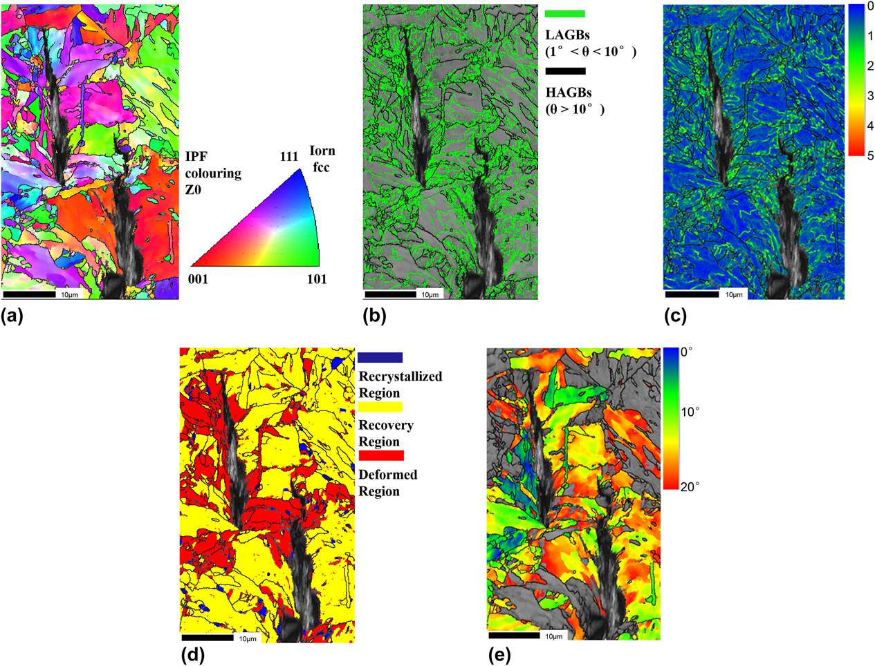
Figure 8(d) shows the recrystallization map around the HIC cracks. The red, yellow, and blue colors represent deformation, substructure, and recrystallization areas, respectively. It can be seen that the deformation in red mainly locates at the crack tip regions. Figure 8(e) exhibits the EBSD map of {110} texture component around the HIC cracks, parallel to the loading direction. The colored zones represent 0°–20° angle deviation. The crystal structure of bainitic ferrite is bcc, and the {110} crystal plane group is the close-packed plane of bcc structures. HIC cracks were clearly shown to mainly propagated along the {110} crystal plane. It could be deducted that the {110} dominant texture increases HIC susceptibility of 12Cr2Mo1R(H) steel.
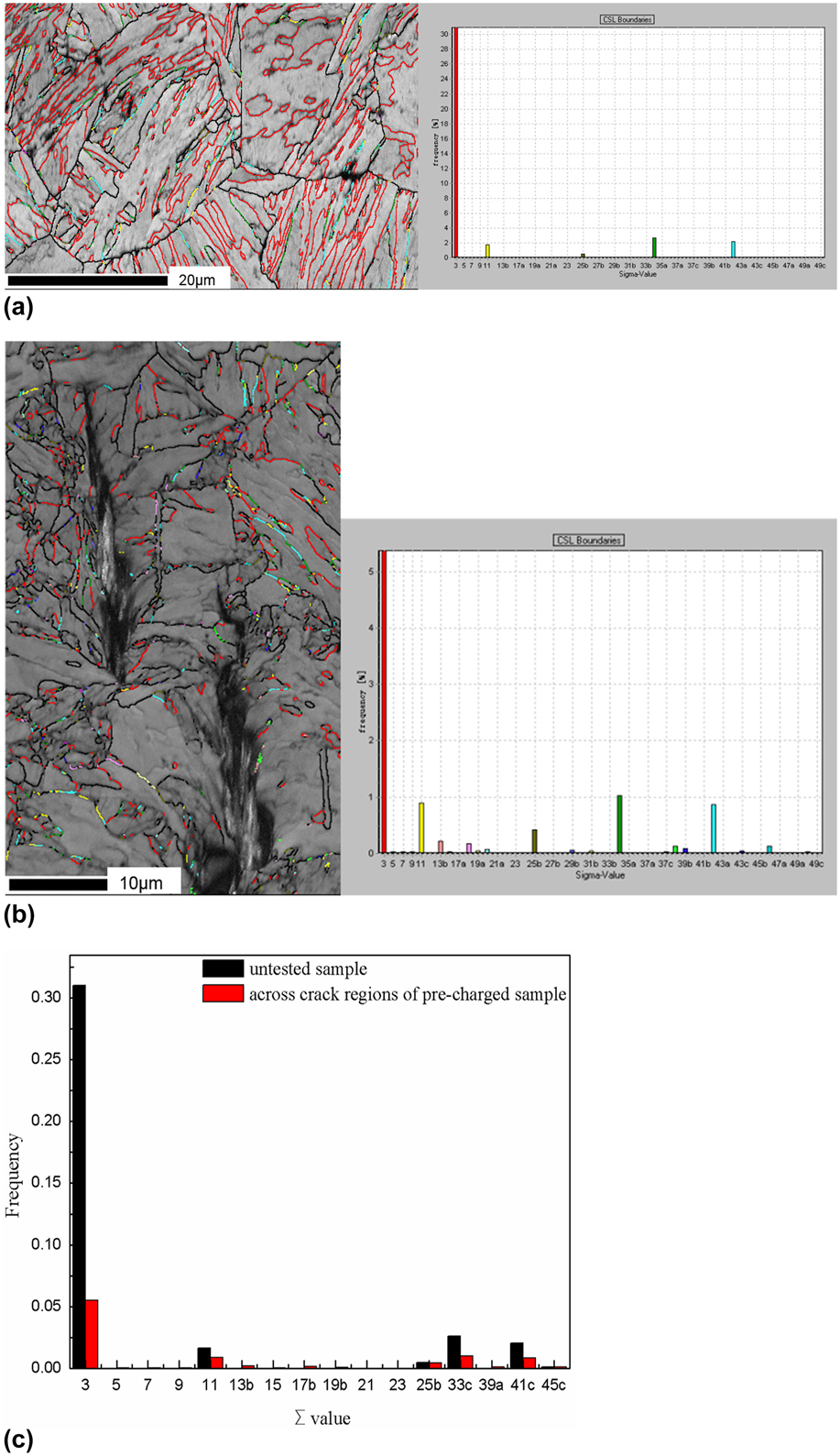
GB is considered as main factors that affect the HIC crack propagation.Reference Arafin and Szpunar17,Reference Jothi, Merzlikin, Croft, Andersson and Brown27 The types of grain boundaries are divided into LAGBs, high-angle (random) grain boundaries, and CSL grain boundaries.Reference Crawford and Was28 The LAGBs have low stored energy, providing higher HIC resistance than random HAGBs. Random HAGBs could serve as propagation paths for HIC cracks due to their high stored energy.Reference Mohtadi-Bonab, Eskandari, Rahman, Ouellet and Szpunar19,Reference Crawford and Was28,Reference Lu and Szpunar29 The GB energy of random HAGBs is much higher than that of LAGBs or CSL grain boundaries. The higher the GB energy is, the larger the lattice distortion of the GBs is and the more unstable the GBs are. The diffusion rate of the hydrogen in GBs is much higher than that in lattice. Therefore, random HAGBs would provide easier path for the hydrogen than LAGBs or CSL grain boundaries. In addition, there should be an autonomous tendency that high GB energy would decrease. Driven by the tendency, hydrogen atoms would be absorbed in the site with high GB energy and aggregate to reduce its GB energy. As a result, the concentration of hydrogen in the site increase and HE susceptibility also increase. The analysis of Fig. 9(a) showed that in the untested sample (the sample without hydrogen charging and tensile test), about 50.04% of the total length of grain boundaries are LAGBs, comparing to 37.94% CSL grain boundaries and only 12.02% random HAGBs. Besides, the bainitic ferrite laths have high density of dislocations. Both dislocations and LAGBs can act as weak reversible hydrogen traps that promote a more homogeneous distribution of hydrogen. As a result, hydrogen accumulation to the critical content at sites of stress concentration and further cracking are impeded.Reference Depover, Wallaert and Verbeken14,Reference Saleh, Hejazi, Gazder, Dunne and Pereloma23
CSL grain boundary maps and their statistics of the (a) untested sample and (b) precharged sample with HIC cracks, and (c) CSL grain boundary histogram of untested and precharged samples with HIC cracks.
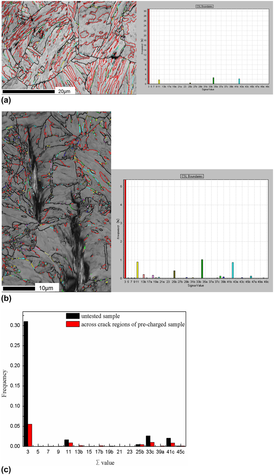
In general, CSL grain boundaries are able to resist HIC propagation due to their low energy. The more CSL grain boundaries a sample possesses, the lower distorted degree its atomic arrangement has, and the lower GB energy it has. Figure 9(b) exhibits the distribution of CSL grain boundaries around the HIC cracks. It is clear that ∑3 grain boundaries have the highest frequency around the HIC cracks. However, the HIC cracks do not propagate along the ∑3 grain boundaries and no ∑3 GB was observed at the crack tips. The phenomena imply that ∑3 grain boundaries would not promote the propagation of HIC. In addition, it is rare to see other CSL grain boundaries distributed closely along the HIC crack path. Figure 9(c) illustrates the frequency histogram of the CSL grain boundaries in the precharged sample with HIC cracks and untested sample. The frequency of ∑3, ∑11, ∑25b, ∑33c, and ∑41c boundaries with low energy in the precharged sample is lower than that in the untested specimen. Therefore, these CSL grain boundaries may increase the sample resistance to HIC. The frequency of ∑13b, ∑17b, ∑39a, ∑39b, and ∑45c in the precharged sample is higher compared to that in the untested sample; however, they were not observed in the crack obstruction area. It was thus unable to determine whether these types of CSL grain boundaries could resist the propagation of HIC cracks.
IV. CONCLUSION
The interaction of hydrogen and 12Cr2Mo1R(H) has been investigated by means of tensile test and EBSD analysis. The maximum EI of ∼20.00% indicates that the steel was not susceptible to HE. Besides, the steel possesses high percentage of LAGBs and CSL grain boundaries, while only 12.02% random HAGBs were found, which would be related to a good HIC resistance. The following conclusions could also be reached.
(1) Hydrogen flaking damage on the fracture surface and HIC cracks on the lateral surface are typical HE characters of the precharged samples. With the decrease of the strain rate and flakes, the flack spreading of precharged samples was further extended.
(2) Most of the HIC cracks propagate transgranularly through the lath grain of bainitic ferrite, while only small amount of HIC cracks diffuse along the lath grain boundaries. The high strain fields are able to deflect the crack tips of two adjacent and parallel cracks toward each another and even form crack coalescence.
(3) Large numbers of LAGBs around the HIC cracks indicate that the regions have high dislocation density. High strain concentration could at the same time induce diffusible hydrogen accumulation at the HIC crack tips.
(4) The result of recrystallization map indicates that the grains with high stored energy around HIC cracks are susceptible to HIC. The {110} dominant texture may increase HIC susceptibility of 12Cr2Mo1R(H) steel.
ACKNOWLEDGMENT
The authors would like to thank the National Natural Science Foundation of China (51201144) and Science & Technology Support Program of Sichuan Province (2016GZ0271) for financial support.