I. INTRODUCTION
A recent wireless communication system uses a signal with a high peak-to-average power ratio (PAPR) to achieve high spectrum efficiency. Using the high PAPR signal requires high input power back-off (IBO) of radio frequency (RF) power amplifier (PA) in wireless transmitter system. The IBO causes the deterioration of the PA efficiency. A linear amplification with nonlinear components (LINC) scheme is one of the efficiency enhancement techniques by decreasing the PAPR of input signal using the outphasing scheme [Reference Cox1]. The PA's input signal is converted into two constant envelope signals with AM/PM modulation by the signal component separator (SCS). However the high PAPR signals lead to low efficiency of combiner in LINC system.
To overcome this problem, multi-level LINC (MLINC) is suggested [Reference Jheng, Chen and Wu2–Reference Aref, Askar, Nafe, Tarar and Negra7]. Instead of using the conventional SCS, a multi-level SCS (MSCS) is used to increase the combiner efficiency. The envelope-adjusting MLINC is suggested in [Reference Jheng, Chen and Wu2, Reference Jheng, Chen and Wu4]. For wideband code division multiple access (WCDMA) signal, the system efficiency is increased from 16.5 to 33.4% using 3-level LINC. The gain-adjusting MLINC is suggested in [Reference Chen, Jheng, Wu, Tsau and Tzeng3, Reference Jheng, Chen and Wu4]. The system efficiency is increased from 16.5 to 23.60% for 3-level LINC. The optimal threshold value is calculated based on the suggested differential equation. A 2-level uneven MLINC system is proposed in [Reference Laskar, Lim, Hur, Kim, Lee and Lee5, Reference Hur, Lee, Kim, Lim and Laskar6]. In [Reference Aref, Askar, Nafe, Tarar and Negra7], a MLINC with signal clipping scheme is proposed. The system efficiency is increased from 28 to 42% and 10 to 33% under WCDMA signal and long term evolution (LTE) signal, respectively.
The key design factor of MLINC system is determination of its threshold values for multi-level. Although a few papers suggest the partial derivatives only to determine the threshold values for MLINC system [Reference Jheng, Chen and Wu2–Reference Jheng, Chen and Wu4], there is a limitation in practical use. It is not easy to determine the threshold values directly from the partial derivatives, because the communication signal is not closed-form, and the partial derivatives could not be solved analytically.
In this paper, we propose a design scheme for MLINC system with multi-level drain supplies to achieve high efficiency and linearity. A 9-point finite difference method (FDM) is suggested to extract optimal threshold values for 3-level LINC system [Reference Borse8, Reference Jo, Shin and Suh9]. The method can extract optimal threshold values efficiently without solving partial derivatives analytically. In addition, a probability density function (PDF) of the input signal is used to determine the initial values of the threshold values. It can reduce the number of iteration and the convergence time of the method. The extracted optimal threshold values are used in MLINC system with dynamic biasing of the PAs.
This paper is organized as follows. In Section II, the architecture of MLINC transmitter is introduced. In Section III, a 9-point FDM is suggested to determine threshold values of 3-level LINC system maximizing the system efficiency. In Section IV, the proposed method is verified using a fabricated PA and simulation with multi-tone signals and LTE signal. The conclusions are drawn in Section V.
II. MLINC TRANSMITTER
A) MLINC system and signals
The conventional SCS of LINC system separates the input signal into two constant amplitude signals. The amplified constant signals are combined in a combiner at output stage. The PA could be operated with its maximum efficiency. However, there is significant efficiency degradation in the isolated combiner. By increasing the number of signal levels, we can improve the efficiency of the combiner and the overall system efficiency. A MLINC system is an extended LINC system that converts the input signal into two constant signals that have several levels.
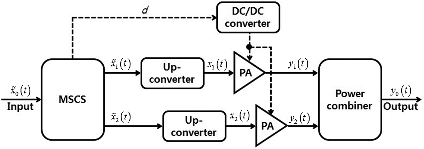
There are two ways to supply the DC power for PAs of MLINC transmitter: a static biasing and a dynamic biasing. The static biasing scheme in MLINC system requires the IBO of PA because the separated signals include multi-level. By using the dynamic biasing scheme, the PA efficiency could be enhanced without deterioration of combiner efficiency. Dynamic biasing schemes are used in envelope tracking, envelope elimination and restoration [Reference Kahn10]. The structure and notations of the signals of the MLINC transmitter system with dynamic biasing are described in Fig. 1.
Block diagram of MLINC transmitter with dynamic biasing scheme.

The system consists of a MSCS, two up-converters, two RF PAs, a power combiner, and a DC/DC converter. For the dynamic biasing scheme, PA supply voltages are changed by the DC/DC converter depending on the separated signal levels as shown in Fig. 1.
The input signal is a band-limited baseband complex envelope signal:
 $$\tilde x_0 (t) = A(t)\,{\rm e}^{j\varphi (t)},$$
where A(t) is amplitude and φ(t) is phase of the input signal. The MSCS separates input signal into two signals that have the same magnitude such as
 $$\tilde x_0 (t) = \tilde x_1 (t) + \tilde x_2 (t),$$
where
 $$\tilde x_{1,2} (t) = c(t)\,{\rm e}^{j(\varphi (t) \pm \alpha (t))}.$$
 $\tilde x_1 (t)$ and
 $\tilde x_2 (t)$ are separated baseband complex signals by MSCS. The c(t) is the magnitude of the separated signals that have discrete levels dependent on the magnitude of A(t). In MLINC system, the signal area is divided into N regions by threshold levels defined as r k (k = 1, 2, …, N − 1) In addition r 0 is defined as the maximum value of |A(t)|, and r N−1 is defined as 0. Threshold values are between 0 and the maximum value of |A(t)| and r k+1 ≤ r k. The magnitude of outphased signals, c(t), is acquired as follows:
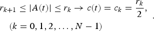 $$\eqalign{& r_{k + 1} \le \vert A(t) \vert \le r_k \to c(t) = c_k = \displaystyle{{r_k} \over 2},\; \cr & \quad (k = 0,1,2, \ldots, N - 1)}.$$
The α(t) is outphasing angle and described as
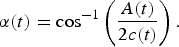 $$\alpha (t) = \cos ^{ - 1} \left( {\displaystyle{{A(t)} \over {2c(t)}}} \right).$$
An example of 3-level LINC is shown in Fig. 2. There are three signal regions (region I, II, and II) and two threshold values (r 1, r 2). The input signal is converted into the separated signals that have three discrete levels (c 0, c 1, and c 2).
MLINC signal separation.
The up-converted signals x 1,2 (t) are real pass-band signals and described as
 $$x_{1,2} (t) = {\rm Re}\left[ {\tilde x_{1,2} (t)\,{\rm e}^{j\omega _c t} {\rm \;}} \right],$$
where ω c is carrier angular frequency. y 1,2(t) are amplified signals of the x 1,2(t) by each RF PAs, and described as follows:
 $$y_{1,2} (t) = {\rm Re}\left[ {g_{1,2} (c(t))\,{\rm e}^{j\left( {\varphi (t) \pm \alpha (t)} \right)} \,{\rm e}^{j\omega _c t} {\rm \;}} \right],$$
where g 1 and g 2 are complex functions that represents AM/AM and AM/PM characteristics of RF PAs. Finally, the output signal y 0(t) is described as
 $$y_0 (t) = y_1 (t) + y_2 (t).$$
B) Efficiency of MLINC
The average efficiency of MLINC system  $\bar \eta _{sys} $ can be acquired in similar way of LINC system such as
 $$\bar \eta _{sys} = \bar \eta _{PA} \cdot \bar \eta _C,$$
where  $\bar \eta _{PA} $ is average efficiency of the PAs and
 $\bar \eta _C $ is average efficiency of the combiner. We use the same PAs in MLINC system, and assume that g 1 and g 2 are the same.
 $\bar \eta _{PA} $ for the input signal x(t) can be acquired as
 $$\bar \eta _{PA} = \int_0^{\max (\vert x(t) \vert)} {\eta _{PA} (\vert x \vert)P_X (\vert x \vert)\,{\rm d}x},$$
where η PA(|x|) is instantaneous efficiency of PA and P X(|x|) is a probability distribution function of the input signal magnitude. |x| is N discrete values as described in equation (4) for MLINC system. In result, the integral in equation (10) can be expressed as the sum such as
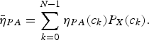 $$\bar \eta _{PA} = \mathop \sum \limits_{k = 0}^{N - 1} \eta _{PA} (c_k )P_X (c_k ).$$
Procedures to calculate  $\bar \eta _{PA} $ for a 2-level LINC with static biasing and with dynamic biasing are shown in Figs 3 and 4, respectively. The input signal is normalized by its maximum input level. The efficiency curve in Fig. 3 is that of class-B PA with static biasing voltage. For the dynamic biasing scheme, the instantaneous efficiency of PA would be maximized by reducing the biasing voltage for a back-off input signal as shown in Fig. 4. In this case, the following condition can be achieved.
 $$\eta _{PA} (c_k ) = \max \; (\eta _{PA} (x)),\quad (k = 0,1,2, \ldots, N - 1).$$
Efficiency of PA of 2-level LINC with static biasing scheme.
Efficiency of PA of 2-level LINC with dynamic biasing scheme.
An instantaneous efficiency η C of the isolated combiner for the separated signals is as follows [Reference Jheng, Chen and Wu2]:
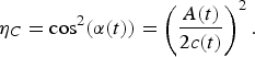 $$\eta _C = \cos ^2 (\alpha (t)) = \left( {\displaystyle{{A(t)} \over {2c(t)}}} \right)^2.$$
The average efficiency of the combiner  $\bar \eta _C $ is acquired by averaging equation (13) such as
 $$\bar \eta _C = \int_0^{\max (\alpha (t))} {\eta _C (\alpha )P_\alpha (\alpha )\,{\rm d}\alpha},$$
where P α(α) is a probability distribution function of the outphased angle. Using equations (9), (11), and (14),  ${\rm \bar \eta} _{{\rm sys}} $ can be extracted. For the given input signal,
 $\bar \eta _{sys} $ is a function of the threshold values r k(k = 1, 2, …, N − 1) because c k and α(t) are functions of r k in equations (4) and (5), respectively.
We define a multi-dimension function that describes  $\bar \eta _{sys} $ with r k (k = 1, 2, …, N − 1) such as
 $$\bar \eta _{sys} = \bar \eta _{PA} \cdot \bar \eta _C = f(r_1, \; r_2, \; \ldots, \; r_{N - 1} ).$$
The condition of threshold values to maximize efficiency of MLINC is as follows:
 $$\eqalign{\displaystyle{{\partial f(r_1, \; r_2, \ldots, \; \; r_{N - 1} )} \over {\partial r_k}} & = 0,\; \; \displaystyle{{\partial ^2 f(r_1, \; r_2, \; \ldots, \; \; r_{N - 1} )} \over {\partial r_k^2}} \cr & \lt 0}.$$
For a 2-level LINC system, there is only one threshold value r 1 and f(·) has only one variable. For the 2-level LINC system that has one threshold value, it is possible to calculate an optimal threshold value analytically even though it is not easy. Simple simulation can be applied to extract an optimal threshold for 2-level LINC system. A fabricated class-AB PA using InGaP HBT transistor with 33.5 dBm P1dB and an LTE-frequency division duplexing (FDD) down link (DL) signal with 64 quadrature amplitude modulation (QAM) are used for the case study. The characteristic of the fabricated PA is described in Fig. 5. A center frequency and bandwidth of the LTE signal are 2140 MHz and 10 MHz, respectively. The PAPR of the signal is 9.28 dB and the PDF of the normalized input signal is shown in Fig. 6. In this case,  $\bar \eta _{PA} $,
 $\bar \eta _C $, and
 $\bar \eta _{sys} $ versus r 1 are calculated and plotted in Fig. 7.
Output power and efficiency of the fabricated class-AB PA.
PDF of LTE signal.
The PA efficiency, combiner efficiency, and system efficiency for 2-level LINC.
However, the 3-level LINC system that has two threshold values, it is complex to get optimal threshold values analytically using equation (16). In the next section, we propose new scheme based on a FDM to find optimal threshold values.
III. A FDM FOR 3-LEVEL LINC SYSTEM
Using equations (15) and (16), conditions for optimal threshold values for 3-level LINC are described as
 $$\displaystyle{{\partial f(r_1, \; r_2 )} \over {\partial r_k}} = 0,\; \quad \displaystyle{{\partial ^2 f(r_1, \; r_2 )} \over {\partial r_k ^2}} \lt 0,\; \quad (k = 1,2).$$
The above partial differential equations can be solved by numerical method. In this paper, a 9-point FDM is applied. The operation of the suggested method can be divided into the following steps:
(1) The first step is to set center point [r 1,m, r 2,m] (m = 0, 1, 2, 3, …) for variables r 1, r 2 (r 1,m > r 2,m), where m represents the number of iterations. For the first iteration, the initial point [r 1,0, r 2,0] must be assigned. There are a number of methods to assign the initial point. The number of iterations depends on the location of the initial point. To reduce the number, the distance between the initial point and the expected optimal point must be small. It is hard to estimate the expected optimal point at the first iteration because it is determined by the various components (the input signal statistics, PA efficiency, combiner efficiency, etc). However, the number of iterations is usually reduced by setting the initial values of r 1,0, r 2,0 at the stochastically evenly distributed points such as
(18) $$\eqalign{r_{1,0} &= \left\{ {\vert x \vert \left \vert {\int_0^{\left \vert x \right \vert} {P_X (a)\,da = \displaystyle{2 \over 3}}} \right.} \right\},\; \; \; \cr r_{2,0} &= \left\{ {\vert x \vert \left \vert {\int_0^{\left \vert x \right \vert} {P_X (a)\,da = \displaystyle{1 \over 3}}} \right.} \right\}.}$$
In this paper, the initial center point [r 1,0, r 2,0] is assigned based on equation (18). For the case, the number of iterations is usually around 10 for the LTE and the multi-tone signals used in the next section.
(2) Next, nine grid points around center values are assigned such as
(19)where i, j = −1, 0, 1. The assigned grid points are shown in Fig. 8. Δr 1 and Δr 2 are differences between grid points as shown in Fig. 8. In equation (19), it is not necessary to be Δr 1 = Δr 2. However it is usually easy to implement MSCS, if Δr 1 = Δr 2. In this paper, we set the same value on Δr 1 and Δr 2.$$\left[ {r_{1,m}^{(i)}, \; r_{2,m}^{(j)}} \right] = [r_{1,m} + i \cdot \Delta r_1, \; r_{2,m} + j \cdot \Delta r_2 ],$$If the difference is too small, it yields the more accurate optimal threshold values, however it needs quite long convergence time. The relationship between the magnitude of interval and convergence time is analyzed in the next section.
(3) Calculate the system efficiency for 9-grid points and define values
$f_m^{(i,j)} $ such as
(20)$$f_m^{(i,j)} = f(r_{1,m}^{(i)}, \; r_{2,m}^{(j)} ).$$Calculate the each difference value
$\Delta f_m^{(i,j)} $ following as
(21)$$\Delta f_m^{(i,j)} = f_m^{(i,j)} - f_m^{(0,0)}.$$(4) Determine the grid point that gives the highest efficiency values and assign it as the centered value of the next step such as
(22)$$[r_{1,m + 1}, \; r_{2,m + 1} ] = \left\{ {[r_{1,m}^{(i)}, \; r_{2,m}^{(j)} ]\left \vert {\mathop {{\rm argmax\;}} \limits_{i,j} \; (\Delta f_m^{(i,j)} )} \right.} \right\}.$$(5) If the [r 1,m+1, r 2,m+1] ≠ [r 1,m, r 2,m], a centered point is updated with new values and iteration is executed again from step 1. If the [r 1,m+1, r 2,m+1] = [r 1,m, r 2,m], we set the values of the current centered point as optimal values. For the optimal values,
$\Delta f_m^{(i,j)} \le 0\; $.


9-grid points to determine the optimal threshold values for 3-level LINC system.
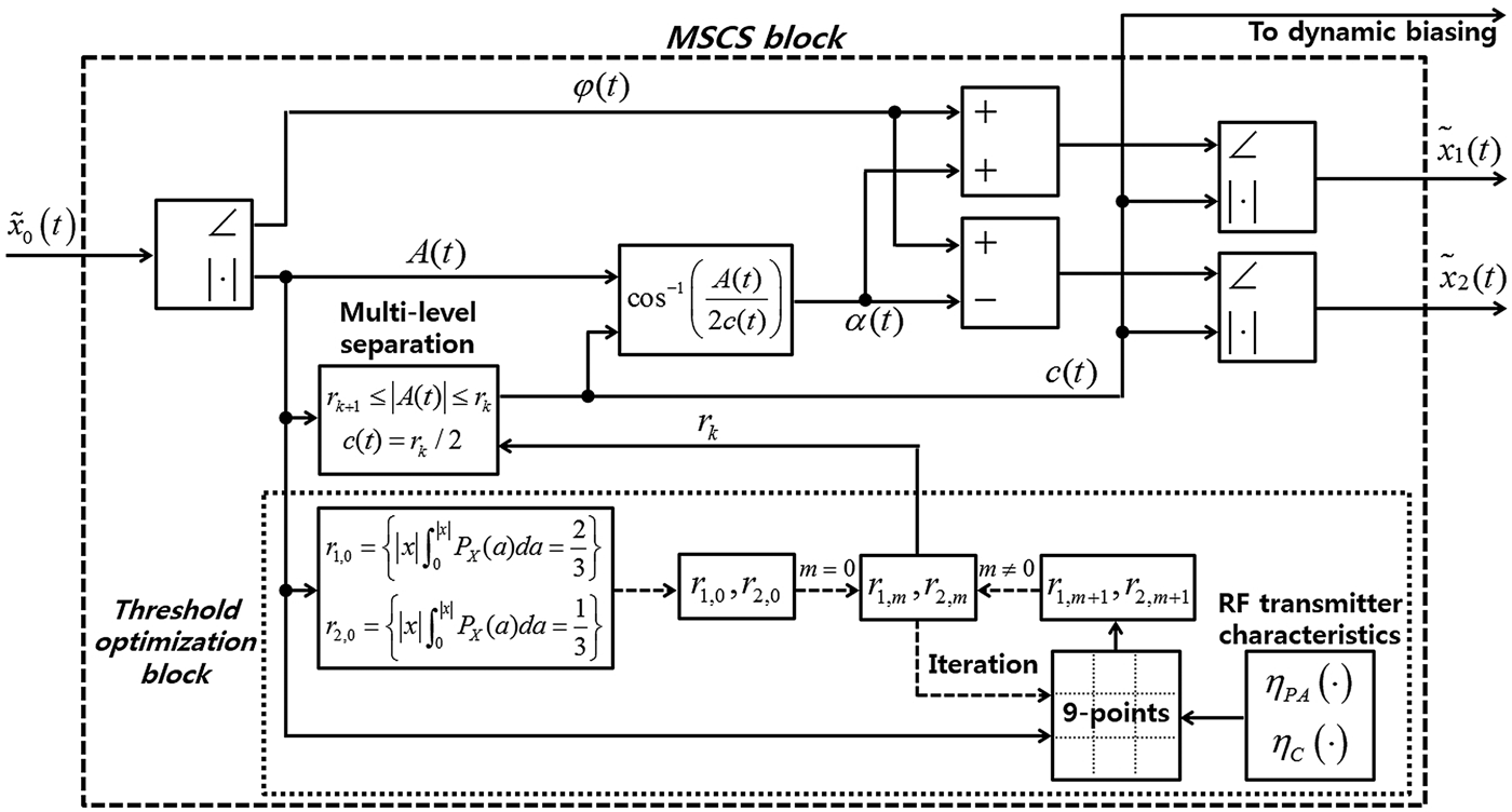
A block diagram of MSCS for 3-level LINC system including the above steps is described in Fig. 9. It shows the process of the signal modulation of MLINC system and the determination of the threshold values. Also the DC bias levels could be determined by the magnitude of separated signals.
The architecture of the proposed MSCS.
IV. VERIFICATION
To verify the suggested scheme, we simulate the system efficiency using the multi-tone signals and the LTE communication signal. Characteristics of a fabricated class-AB PA using an InGaP HBT transistor with 33.5 dBm P1dB is measured and considered for the simulation.
A) Case for multi-tone signals
The optimal threshold values of the 3-level LINC system are extracted using the proposed method for various multi-tone signals. In Fig. 10, the PAPRs of the multi-tone signals are plotted versus the number of tones. The system efficiencies of the conventional LINC, 2-level LINC, and 3-level LINC for the various multi-tone signals are simulated and compared in Fig. 10. The 3-level LINC system increases the system efficiency significantly. For an 8-tone signal, efficiencies of the conventional LINC, 2-level LINC, and 3-level LINC are 9.5, 27.2, and 36.5%, respectively.
Comparison of system efficiencies (LINC, 2-level, and 3-level LINC) for multi-tone signals.
Two signal paths that form the LINC systems have unavoidable path imbalance on their gain and phase difference. Gain and phase mismatches will cause the significant deterioration in linearity of the system [Reference Lim, Kang and Ku11, Reference Guan, Aref, Hone and Negra12]. We analyze an error vector magnitude (EVM) of the multi-tone signals considering the effect of path imbalance (GR, gain ratio between two paths; PE, phase error between two paths). In Fig. 11, EVMs are simulated and compared for the system with GR = 90%, PE = 5°. The results show that 3-level LINC system has less EVM for the same path imbalance comparing with LINC and 2-level LINC system because 3-level LINC system can reduce the amount of the out-phased angles compared with other systems. The advantage of MLINC system for linearity performance is also addressed in [Reference Guan, Aref, Hone and Negra12].
EVM of LINC, 2-level and 3-level LINC with (GR = 90%, PE = 5°).
B) Case for LTE signal
For an LTE-FDD DL with 64QAM signal with 2140 MHz center frequency, the system efficiencies versus r 1 and r 2 for the 3-level LINC are extracted and plotted in Fig. 12. The extracted optimized threshold r 1, r 2 values using the suggested scheme are shown in Fig. 12. Using these values, the maximized system efficiency can be achieved. In addition, by using the dynamic biasing scheme, the efficiency of PA could keep as maximum efficiency although the input power level is changed.
Optimization for maximum efficiency of 3-level LINC.
The effects of magnitude of the step size (considering Δr 1 = Δr 2 = Δr) on the performance and iteration numbers are shown in Fig. 13. A trade-off occurs between the system efficiency and the number of iterations.
The number of iterations and system efficiency versus magnitude of Δr 1, Δr 2.
To extract accurate optimal threshold values, the Δr should be small, but the number of iterations increases. In Fig. 13, if the Δr is larger than 0.12 r 0, the number of iterations is 1 and the system efficiency decreases significantly. Considering the number of iteration and the system efficiency, Δr = 0.08r 0 is a reasonable compromise considering performance and number of iterations.
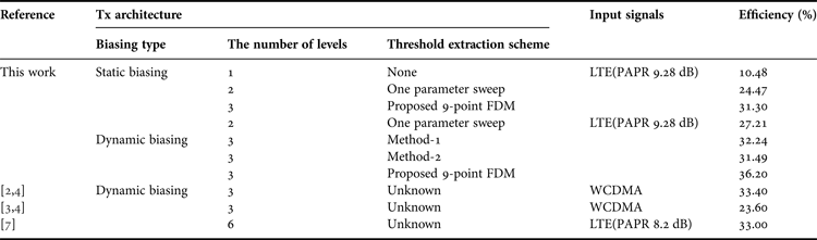
To maximize the system efficiency, threshold values are extracted by setting Δr = 0.01. In this case the number of iterations is 15 as shown in Fig. 13. The system efficiencies are increased by 20.82 and 6.83%, respectively, compared with the conventional LINC system and 2-level LINC system using the proposed 3-level LINC system with static biasing for the LTE signal. If the dynamic biasing is applied, the maximum system efficiency of the proposed scheme is 36.2%. This is higher than those of the published MLINC's pre-works [Reference Jheng, Chen and Wu2–Reference Aref, Askar, Nafe, Tarar and Negra7]. The efficiency of the MLINC system is summarized in Table 1. In Table 1, the performance of the proposed method is compared with those of the MLINC system with other methods. Method-1: one method is deciding r 2 at the input level with maximum PDF and r 1 at the midpoint r 2 and maximum input level. Method-2: another method is deciding r 2 and r 1 at the one-third and two-third of maximum input level, respectively.
Overall system efficiency of the MLINC system for the LTE signal.
V. CONCLUSION
In this paper, a MLINC transmitter architecture was proposed to improve power efficiency of the transmitter. For 3-level separation, a 9-point different method was suggested to extract optimal threshold values numerically.
The suggested algorithm was assessed by exciting a 3-level LINC transmitter with two different signals: one with multi-tone signals and LTE signal. The proposed scheme showed accurate extraction of optimal threshold values efficiently. The transmitter with the proposed MSCS improved power efficiency of the system significantly. Indeed, the distortion occurring from the path imbalances was reduced with the proposed architecture. The proposed scheme can be applied to the design of high efficient wireless transmitter system.
ACKNOWLEDGEMENT
This research was supported by Konkuk University, 2014
Jonggyun Lim received the B.S. in Information and Electronic engineering from the Seoil University and National Institute for Lifelong Education, Seoul, Korea, in 2009, and received the M.S. degrees in Electronic engineering, School of Information and Communication, Konkuk University, Seoul, Korea, in 2011. Since March 2011, he is currently working toward the Ph.D. degree in Electronic engineering, School of Information and Communication, Konkuk University, Seoul, Korea. His research interests are high efficient RF PA and transmitter system, behavioral modeling/characterization of RF devices, linearization of power amplifier, Optics, and design of wireless power transfer circuit/system.
 Hyunchul Ku received his B.S. and M.S. degrees in Electrical Engineering from Seoul National University, Seoul, Korea, in 1995 and 1997, respectively, and Ph.D. degree in Electrical and Computer Engineering from Georgia Institute of Technology, Atlanta, USA, in 2003. He worked as a researcher in Korea telecom from 1997 to 1999 and as a senior engineer in Samsung electronics from 2004 to 2005. He is presently a Professor with the department of electronic engineering, School of Information and Communication, Konkuk University, Seoul, Korea. His research interests are behavioral modeling/characterization of RF devices, linearization of power amplifier, design of intelligent RF system, and design of wireless power transfer circuit/system.