I. INTRODUCTION
The four largest contributing mechanisms that account for losses in electromagnetic (EM) signal propagation are frequency-dependent free-space losses, reflection, diffraction, and scattering. In the millimeter-wave (mm-wave) frequency band near 60 GHz, mechanisms such as oxygen absorption and rain-rate attenuation become significant contributors to the overall losses and must be prioritized to estimate the coverage area of transmitted radio signals [Reference Wang, Prasad and Niemegeers1]. This paper analyzes the expected EM signal attenuation over a short distance (<30 m) as a function of free-space losses, oxygen absorption, reflection, and diffraction losses, as well as rain-rate attenuation with climate conditions specific to South Africa, but presented as a general model. The paper proposes two low-pass filter (LPF) structures to simulate expected environmental conditions based on these mechanisms. The filters are implemented in 130 nm bipolar complementary metal-oxide semiconductor (BiCMOS) integrated circuit (IC) using pre-characterized standard passive components to satisfy topology requirements, and an active component to emulate variable attenuation.
Studies on the attenuation of mm-wave signals have presented practical experiments to determine, through geometrical optics ray-tracing techniques, line-of-sight (LOS), and non-LOS (nLOS) attenuation as a function of material complex permittivity, and moving transceiver losses. The data obtained in these experiments [Reference Moraitis and Constantinou2, Reference Fakharzadeh, Nezhad-Ahmadi, Biglarbegian, Ahmadi-Shokouh and Safavi-Naeine3] provide practical results to give a relative estimation of expected attenuation at mm-wave frequencies. Experiments are however restricted to the environment itself, and the availability of the required equipment to simulate such conditions. Controlling these environmental parameters on an integrated level, with external variables (such as an externally applied voltage) increases the diversity of experiments.
To change the amplitude characteristics of the radio signal, passive filters (less stringent bandwidth limitations although physically larger compared to active filters) based on the Butterworth and Chebyshev topologies were simulated and prototyped. Since transmitter power (P T) is related to antenna gain (G a), receiver sensitivity (S min), and path-loss (PL), within the relationship given in [Reference Biglarbegian, Fakharzadeh, Busiuoc, Nezhad-Ahmadi and Safavi-Naeini4],
 $${P_T}+2{G_a} \geq {S_{min}} - PL\comma$$
where the left-hand side of (1) allows degrees of freedom to change parameters for improving performance, the right-hand side of (1) is standard [Reference Biglarbegian, Fakharzadeh, Busiuoc, Nezhad-Ahmadi and Safavi-Naeini4]. Representing and incorporating PL on-chip adds degrees of freedom to determine transfer characteristics and mechanisms that have the biggest contribution on attenuation. Passive filters include inductor–capacitor (LC) configurations, radiofrequency (RF)-microelectromechanical systems (RF-MEMS), and electroacoustic filters. LC filter configurations are the most generally used filters; however, at higher frequencies the bandwidth of the filter depends on the Q-factor of the LC, which could be a limiting factor depending on the technology process. Low insertion loss planar filter structures have been proposed in [Reference Biglarbegian, Fakharzadeh, Busiuoc, Nezhad-Ahmadi and Safavi-Naeini4, Reference Lin, Chang and Lin5]; however, including two additional inductors to move the high-frequency transmission zero to a finite frequency, increases the already large chip area. In this paper, transmission lines were used as the (inductive) passive components (as opposed to larger spiral inductors) as the high-frequency operation permits practical geometries of these components.
The contribution to the current body of scholarly knowledge based on estimated link-attenuation is provided through identifying the considerations when modeling passive structures at mm-wave frequencies. EM simulations do provide modeling alternatives to account for high-frequency effects. This research work takes forward the representation of these mm-wave effects from the perspective of circuit designers and provides a baseline for expanding and understanding expected losses at mm-wave frequencies. The paper demonstrates the ability to model these losses using circuit theory and IC prototyping as opposed to recreating various scenarios of such communication links, in order to decrease time between experiments.
The proposed path-loss prediction model and the filter structures are presented in the following sections.
II. MECHANISM DESCRIPTIONS
The considered mechanisms and proposed integrated structures are presented in this section. Radio signal path-loss estimations specific to South Africa, expandable to other regions, in the mm-wave frequency range are presented to estimate the attenuation in short-range wireless transmissions. Passive filter structures within a 130-nm technology node are presented to represent this estimated radio-signal attenuation on the integrated level. The filters are to be used in conjunction with equivalent-circuit antenna models, or off-chip antenna elements [Reference Fakharzadeh, Nezhad-Ahmadi, Biglarbegian, Ahmadi-Shokouh and Safavi-Naeine3], by radio amateurs to predict attenuation in an analog real-time laboratory environment. Further improvements to the degrees of freedom within (1) on an integrated level; include modeling the antenna as an equivalent circuit, and incorporating this circuit on the IC.
A) Mm-wave path losses
The largest detriment of radio-signal transmission is wavelength-dependent (inversely) free-space attenuation. These losses also depend on the transmitted power, the distance between the transmitter and the receiver, as well as the antenna (transmit and receive) gain. The Friis free-space equation [Reference Chuang, Yeh, Kuo, Tsai and Yue6] is simplified at 60 GHz and given by (assuming transmit and receiving antenna gain of 0 dB)
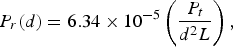 $${P_r}\lpar d\rpar =6.34 \times {10^{ - 5}}\left({\displaystyle{{{P_t}} \over {{d^2}L}}} \right)\comma$$
where P r(d) is the power received by the receiving antenna (in Watt (W)) at a distance d (in m), P t is the transmitted power (W), and L is the system loss factor (assuming L ≥ 1). In this work, L = 1, and suggests no losses in the system due to transmission line attenuation, filter losses, or arbitrary antenna losses (these losses are estimated, but not within the scope of this paper). Combining (2) with losses experienced by nLOS obstructions (dependent on the density of the material and the angle of incidence), the estimated attenuation of the radio signal can be determined.
Oxygen absorption is estimated using the Van Vleck [Reference Van Vleck7] absorption coefficient in an approximate formula for both the non-resonant absorption and the absorption by the tails of the 60 GHz frequency band, at approximately 10–15 dB/km (0.01–0.015 dB/m) at sea level (20.9% oxygen). At higher altitudes (such as temperate climatic regions), a lower oxygen percentage results in lower oxygen absorption, therefore the lesser value of 0.01 dB/m can be used.
Reflection and diffraction losses are determined using Maxwell's equations to determine return losses (RL[dB] = −20 × log10|Г|, where Г represents the reflection coefficient for the vertical and/or the horizontal electric fields) as a function of incident and reflected waves, and the Fresnel zone knife-edge diffraction model [Reference Wang, Prasad and Niemegeers1], respectively. The attenuation of the Fresnel zone knife-edge diffraction model is determined by G d[dB] = 20 × log10|F(v)|, where F(v) = 6.9 + 20 × log10[((v − 0.1)2 + 1)1/2 + v − 0.1] for v > 0.7 and F(v) = 0 for v < 0.7 (where v is the Fresnel–Kirchoff diffraction parameter [Reference Wang, Prasad and Niemegeers1]). The diffraction gain follows an overshoot-type function (with theoretical positive gain) for Fresnel diffraction parameters below v = −0.75 (simplified to 0 dB) and the gain decreases at approximately −5 dB per decade and reaches its asymptote at −28 dB for v > 5 [Reference Wang, Prasad and Niemegeers1]. The Fresnel diffraction parameter as a function of attenuation can be simulated by an LPF structure as proposed; however, dependent on the maximum variable attenuation attainable of the filter structure. Reflection and diffraction losses are required if considering nLOS transmissions, as these losses are additional to attenuation of penetration resistance.
Additionally, attenuation of 60 GHz radio signals as a function of rain-rate (K(d 0) in dB) is approximated from [Reference Chuang, Yeh, Kuo, Tsai and Yue6] as K(d 0) = 1398 × d 0 × R 0.0031 in dB, where R is the rain-rate in mm/h. Rain-rate figures are dependent on designated climatic regions (specific areas typically found in South Africa [Reference Mulangu and Afullo8] are referenced in this paper; however, the model can be applied to any region). These regions include desert areas (R 0.01 ≤ 5 mm/h, where R 0.01 specifies a rainfall rate distribution probability of 0.01%, with an integration time of 1 min as specified in [Reference Mulangu and Afullo8]), Mediterranean areas (R 0.01 of ~50 mm/h) and temperate climatic regions with R 0.01 ≥ 150 mm/h. This paper proposed a total path-loss prediction model (TL(d 0) in dB) at reference distance d 0 (in m) given by
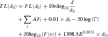 $$\eqalign{TL\lpar {d_0}\rpar & = PL\lpar {d_0}\rpar +10n{\log _{10}}\displaystyle{d \over {{d_0}}}\cr & +\mathop \sum \limits_i A{F_i}+0.01 \times {d_0} - 20\log \left\vert {\rm \Gamma } \right\vert \cr & +20{\log _{10}}\left\vert {F\lpar v\rpar } \right\vert +1398.5{R^{0.0031}} \times {d_0}\comma}$$
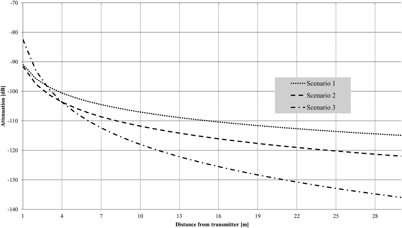
where n is a characteristic path-loss exponent based on the environment and ΣiAF i is the sum of the attenuation in dB of the signal due to interfering objects that tend to break the LOS. The results of this attenuation function for three different scenarios as described in Table 1 are given in Fig. 1.
Proposed attenuation function results for three different scenarios.

Parameters of simulated scenarios for proposed attenuation function.
The results in Fig. 1 compare well with [Reference Fakharzadeh, Nezhad-Ahmadi, Biglarbegian, Ahmadi-Shokouh and Safavi-Naeine3, Reference Biglarbegian, Fakharzadeh, Busiuoc, Nezhad-Ahmadi and Safavi-Naeini4] and present attenuation of between −80 and −140 dB experienced with varied distance 0.01 < d 0 < 30 m. This model (3) is therefore used to compare the attainable LPF attenuation and varied with a direct current external input signal to the 130 nm node IC. The work presented in [Reference Zhadobov, Chahat, Sauleau, Le Quement and Le Drean9] presents attenuation within the 60 GHz band from biological targets with reflections and transmission at the skin/air interface, absorption in the skin, and influence of clothing, and this work can be applied to such studies to further increase the amount of parameters considered in the attenuation model. The determination of the physical layer, and link-budget for 60 GHz systems, given in [Reference Krone10], can also benefit from analog representations of the transmitted signal for real-time analysis and verification of acquired results.
B) Passive filter structures
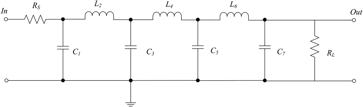
The order of the Butterworth and Chebyshev filters was determined by analyzing its respective amplitude response (A dB) transfer functions. The Butterworth filter required a seventh-order structure to allow sufficient attenuation in the 130 nm BiCMOS node, with −3 dB cut-off frequency (ω c) of 10 GHz. This value was obtained through the first-order approximation of the amplitude response given by A dB = 10log10[1 + (ω/ω c)2N], where N is the filter order and ω is the operating frequency. The attenuation achieved at 60 GHz using these parameters is 108.94 dB. The Chebyshev filter also required a seventh-order structure, with a cut-off frequency of approximately 19 GHz (as it has a sharper roll-off), and estimated ripple of 0.01 dB within the pass-band. The ratio of ω/ω c [Reference Bowick, Ajluni and Blyler11] to achieve attenuation of approximately 100 dB at 60 GHz relates to a value of 3.5 (taking into account the ripple). The attenuation achieved at 60 GHz is equal to 96.81 dB for the Chebyshev filter using these parameters. The structure for both filters is given in Fig. 2, where the inductive components (L ∝ R L/f c) are realized using transmission lines and the capacitive components (C ∝ 1/R Lf c) are realized using metal–insulator–metal (MIM) capacitors. Parasitic pad-capacitances were accounted for at the input and output of the structure through matching and buffer circuits.
Seventh-order LPF topology.
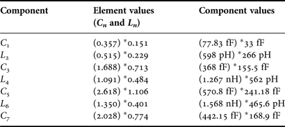
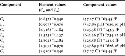
Component values for the Butterworth and Chebyshev filters are summarized in Tables 2 and 3, respectively. The component values for both filters were simulated initially using ideal components in a SPICE-based environment. The element values and component values are given in brackets in Tables 2 and 3. For each simulation however, the IBM 130 nm BiCMOS node library components were also introduced in order to facilitate a prototype design for this process. To achieve desirable results in this process, the performance specifications (attenuation) were relaxed to approximately 60 dB at 60 GHz. This achieved more predictable and repeatable results, while still investigating the hypothesis. The actual component values (including its parasitic effects) are given in Tables 2 and 3, preceded by an asterisk. These values were used during the layout design, as opposed to the ideal values (in brackets) to facilitate the 130 nm process, and prototyped and measured (see Figs 8 and 9). The values of R S and R L used are 50 and 73 Ω, respectively. A dipole antenna with 180° separation was connected to each filter, and the theoretical (and simulated) impedance seen by the filter equals 73 Ω; therefore R L = 73 Ω. The element values C n and L n obtained in [Reference Bowick, Ajluni and Blyler11] were de-normalized to determine the component values C and L by C = C n/2πf cR L and L = L nR L/2πf c.
Component values for Butterworth LPF.
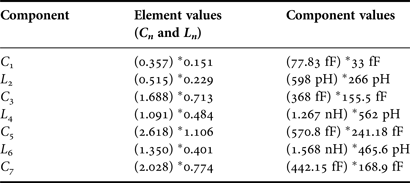
Component values for Chebyshev LPF.
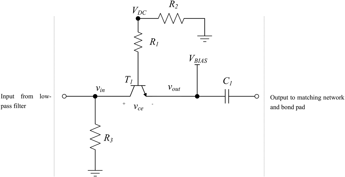
The component values were calculated to allow maximum power transfer to and from a radiating structure (dipole) that can be connected on the same IC. This allows predicting radio-signal transmission behavior between two radiating structures, with integrated atmospheric-specific attenuation, on a single IC. With regards to the circuit layout, a drawback of using microstrip-lines on silicon technologies is the close proximity of the ground plane to the signal line, which yields a small distributed inductance, degrading the inductive quality factor, Q L. To decrease resistive and capacitive losses of the microstrip-lines, the top-most metal layer of the node was used as it allows thicker and wider (to reduce the total resistance and capacitance and maximize characteristic impedance) signal lines to achieve higher accuracy in both simulations and measurements. Adjacent transmission lines were placed at distances larger than the minimum required as specified by the process technology to decrease mutual coupling at the expense of the surface area. The capacitive components were implemented with non-variable MIM capacitors since no varied input signal was required for these components. Variable attenuation was accomplished using a common-base transistor amplifier with no gain and a variable DC input on the base of the transistor. The common-base configuration is shown in Fig. 3.
Common-base transistor amplifier to simulate changes in environmental conditions.
From Fig. 3, transistor T 1 was used to decrease the filter attenuation from unity gain (g mR 3). The voltage V DC is applied to the base of T 1 through a resistor R 1 (100 Ω) to achieve the desired quiescent point. In order to establish a collector current, resistor R 2 (4.7 kΩ) is placed between the source (V DC) and the (DC) ground and R 3 (1 kΩ) sinks a portion of the current flowing toward the collector of T 1. The variable input voltage (V BIAS) is externally introduced at the emitter of T 1 to allow for a variable positive voltage supply to be applied with respect to the transistor base, allowing significant attenuation of the input (from the preceding LPF) AC signal. The additional DC-offset to the AC signal at this stage is removed through capacitor C 1 placed between the common-base active circuit and the following matching circuit and finally the bond pads, where the measurements are taken.
The maximum allowed voltage-dependent variable capacitance ratio required (C min/C max), increases with larger order filters (seventh-order filter used) and presented very little variable attenuation. The maximum ratio (as specified within the process technology) did not allow for variable attenuation >±0.3 dB and therefore an active component was introduced. Simulation results confirmed no detrimental effects of the active device with respect to additional noise or attenuation beyond the required performance. The filters were prototyped and measured using an on-wafer probe station, 40 MHz–110 GHz vector network analyzer (VNA), and variable DC supply. Figure 4 is a micrograph of the prototyped filters.
Micrograph of the prototyped Butterworth (left) and Chebyshev (right) LPFs.
The dimensions for the prototyped filters within the 130 nm node are also given in Fig. 4. External variable signals were introduced to the filters by the 150 × 150 µm pads visible at the bottom of Fig. 4.
C) Integration of the antenna
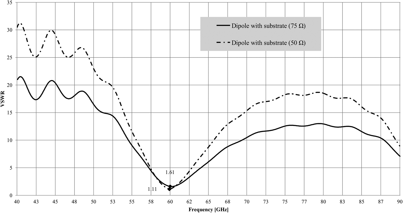
A dipole was electromagnetically simulated as a half-wavelength dipole (λ/2). This section only serves an introductory purpose and a detailed analysis on dipole antenna modeling and interconnections with adjacent circuits is presented in [Reference Lambrechts and Sinha12]. Half-wavelength antennas have several advantages such as a radiation pattern that is omnidirectional in the H-plane, ensuring relevance of proposed simulated results to practical applications (this type of radiation pattern is required for mobile applications). It has a directivity of 1.64 or 2.15 dB and is higher than short dipole directivity (although lower than a full-wavelength dipole). The full-wavelength dipole however is larger in size therefore this is a trade-off between size and directivity. The length (L = λ/2) of the proposed dipole is 2.5 mm; therefore each conductive strip (L/2 = λ/4) is 1.25 mm long. This topology yields the largest differential voltage therefore generating the largest current. The two conductive strips are connected by a center-fed excitation port. The voltage standing wave ratio of the simulated dipole is presented in Fig. 5.
Simulated voltage standing wave ratio for the antenna.
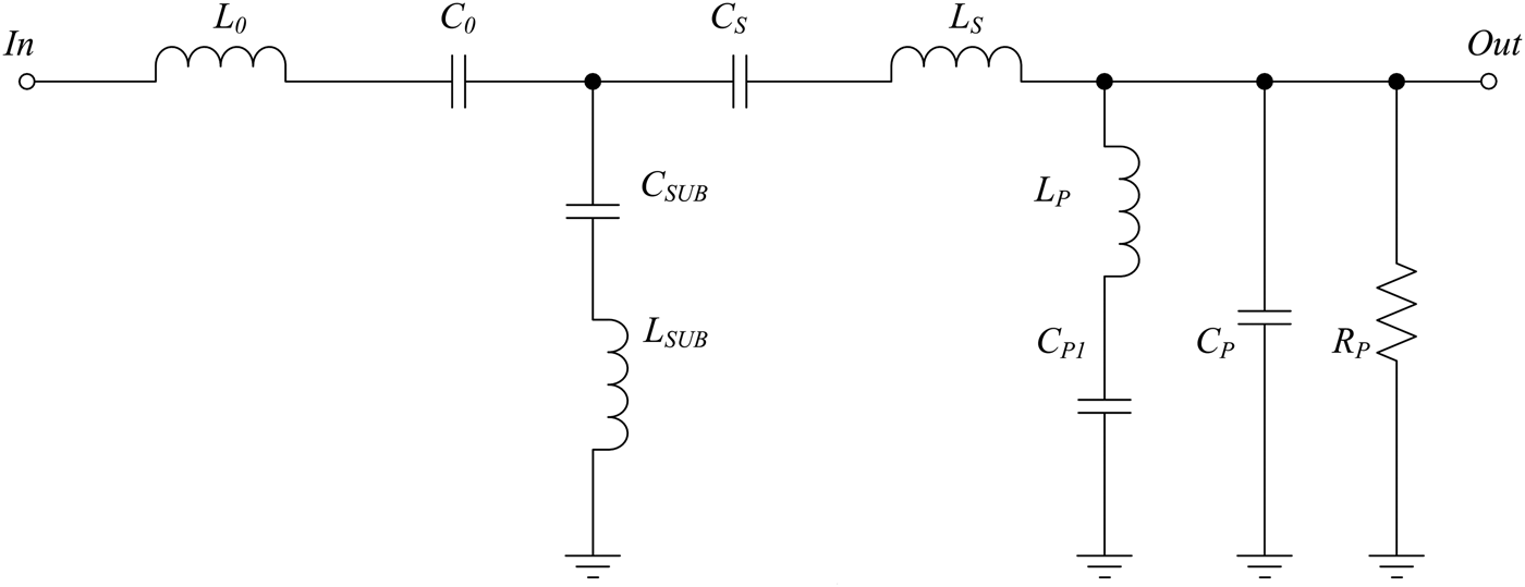
Additional accuracy of the path-loss predictions is achieved through representing and incorporating the antenna as an equivalent circuit (taking into account parasitic and substrate effects). The equivalent circuit model for this antenna is presented in Fig. 6. The detailed analysis of this circuit is presented in [Reference Lambrechts and Sinha12] and this section only introduces the option to include the antenna equivalent circuit with the integrated filters for full system-on-chip (SOC) integration.
Equivalent circuit for the mm-wave dipole.
From Fig. 6, representing a modified and extended version of the Foster canonical form for electrical antennas, C SUB and L SUB represent the parasitic elements introduced by the (silicon) substrate beneath the dipole. C S and L S are series resonant capacitive and inductive elements between the parallel resonant components, and L P and C P1 add two more degrees of freedom to the attainable range of the minimum and maximum imaginary impedance within the node. The simulated and measured results for the antenna equivalent circuit are given in Fig. 7.
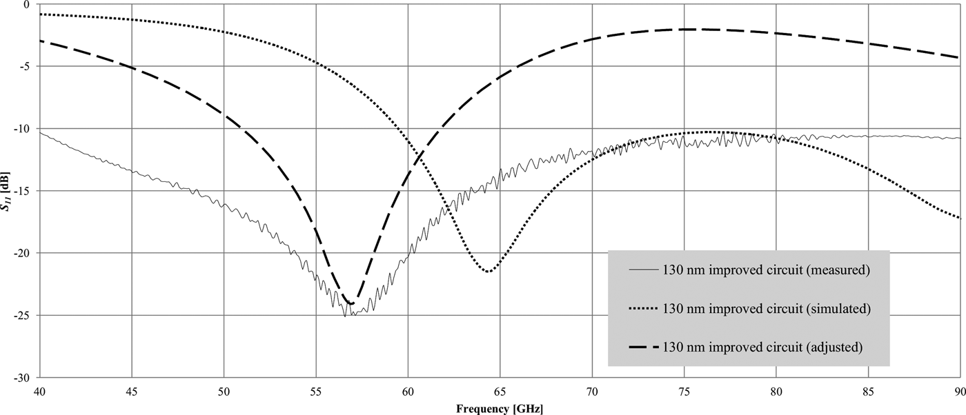
Simulated and measured results for the equivalent circuit.
The results are obtained for the dipole equivalent circuit, given in Fig. 7. S 11 for the measured dipole equivalent circuit (thin solid line) is −24 dB at 56.7 GHz (resonance). It was determined that the shift in resonance was due to an improper grounding strategy, and investigation into the additional inductive parasitic components added to the circuits was analyzed. These adjustments were also added to Fig. 7 to verify the transfer characteristics when considering a shift in resonant frequency. These results are fed into the input of the integrated LPF where normally an ideal mathematical solution, or separate EM simulation would be used as the filter input.
III. FILTER RESULTS
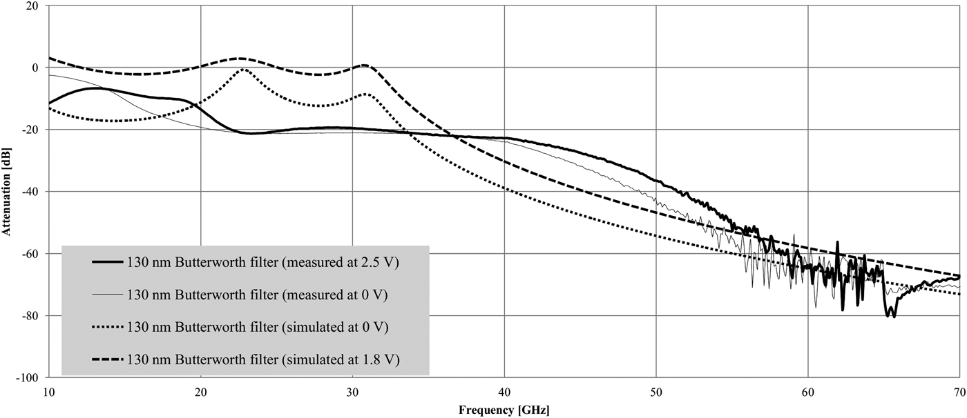
The simulated and measured results for the Butterworth seventh-order LPF with a Δ1.8 V DC (in simulation) and Δ2.5 V DC (during measurements as a larger variation in output was visible above 1.8 V DC while maintaining a safe operating voltage) variable input are depicted in Fig. 8. Simulated results are only obtained from 10 GHz onwards where the positive values of insertion loss below 30 GHz are a result of deviation of the common-base transistor amplifier gain characteristics at these frequencies.
Simulated and measured results of Butterworth LPF with varied input.
The simulated filter presented a minimum attenuation of −57.6 dB at 60 GHz and a maximum of −64.2 dB by varying the input (attenuation of Δ6.6 dB achieved). Simulated results below 30 GHz of the biased (1.8 V DC) filter displayed approximately 0 dB attenuation (within the pass-band), whereas with 0 V DC input, attenuation reached values of up to −18 dB as a result of device parasitics and losses within transmission lines at parasitic-resonance. A maximum attenuation of −83 dB (−100 dB required based on (2) at 60 GHz) was achieved at f > 90 GHz as a result of device limitations on minimum component sizes for this technology node. The relaxed specifications resulted in the second set of parameter values given in Tables 2 and 3, preceded by an asterisk. Mismatches of attenuation at frequencies below approximately 50 GHz are attributed to design optimization and matching about 60 GHz to ensure correct operation at these frequencies of interest. Device parasitics and mismatches at lower frequencies would require a very large bandwidth consideration and was not the focus of this work. Measurement results using the on-wafer probing station introduced minimal parasitic inductances and presented some additional attenuation within the pass-band. The filter transfer curves and cut-off frequencies obtained were optimized for the specific technology node to follow the specified attenuation as closely as possible.
The hypothesis is not only dependent on the achievable values and can still be verified even if component value limitations and additional parasitic effects influence attainable values, and additional component values had to be specified for the 130 nm node. The parallel placement (as opposed to perpendicular placement) of the transmission lines (although exceeding the recommended separation distance) and the thin (relative to the transmission line width) ground plane presented parasitic parameters within the structure. Attenuation at higher frequencies (f > 70 GHz) could not be maintained as a result of components operating passed its tested frequencies and noise and mismatches added to the circuit during frequency up-conversion up to 110 GHz (from the device-specified 67 GHz). These effects were accounted for and the resulting transfer characteristics are given in Fig. 8. Applying a multivariate linear regression function to the output, a minimum attenuation of −45 dB was achieved at 60 GHz, with a maximum of −47 dB with Δ2.5 V DC input to the base of the transistor, achieving only Δ2 dB of variable attenuation.
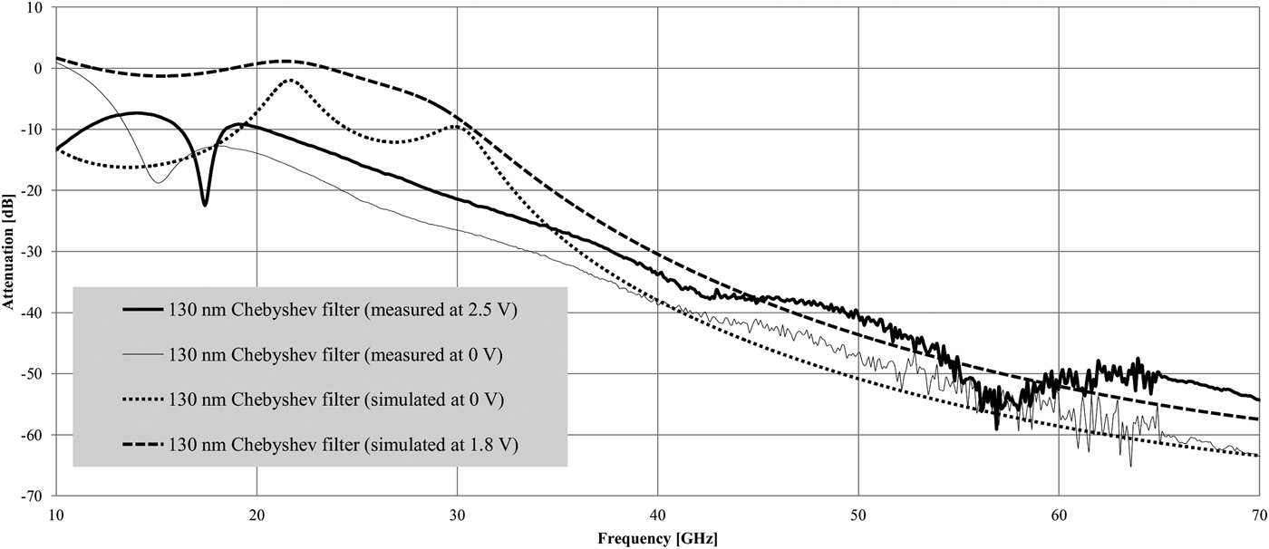
The simulated and measured results for the Chebyshev seventh-order LPF are given in Fig. 9.
Simulated and measured results of Chebyshev LPF with varied input.
Simulated results in Fig. 9 achieved a minimum attenuation at 60 GHz of −51.6 dB and a maximum of −58.2 dB with a Δ1.8 V DC input, constituting a variable attenuation of Δ6.6 dB (with the simulation profile starting at f = 10 GHz onwards). Measured results showed a similar trend as with the Butterworth LPF (Fig. 8) and when accounting for these effects and applying a similar multivariate linear regression predictor model, an estimated minimum attenuation of −50 dB (60 GHz) and maximum of −55 dB with Δ2.5 V DC input signal (therefore Δ5 dB) was achieved as in Fig. 9. This result suggested the use of a Chebyshev seventh-order LPF structure to achieve the highest variable attenuation.
IV. CONCLUSION
This paper investigates the propagation losses of mm-wave radio signals within the 57–64 GHz (unlicensed) frequency band as a function of free-space attenuation, oxygen absorption, reflection and diffraction, and rain-rate attenuation data collected from the available weather-service resources. Through acquiring and modeling this data, this paper proposes a function (3) to estimate overall losses over a short distance, practically attainable with such high-frequency transmissions. These results are compared with current literature for compliance and are used as a guideline to design passive, variable, LPFs on an IC within a 130 nm node where integration with radiating structure equivalent circuits could represent a transmission environment. The range achieved in varying the attenuation within a seventh-order filter confirms that a relatively high dynamic range of environmental conditions with diverse complexity can be represented. Also concluded is that the Chebyshev LPF presents the largest adjustable attenuation (measured) of the two structures (Δ5 dB). Measured results showed good correlation with simulated results, with additional attenuation introduced within the pass-band (f < 30 GHz). Improvements to the ground plane as well as transmission line placement and geometry, and eliminating the frequency conversion to allow measurements up to 110 GHz could improve accuracy and reduce noise in measurements. The proposed mathematical model (3) can also be efficiently used in MATLAB® for a first-order approximation and estimation of expected attenuation within its operated frequency, and can be increased or reduced in complexity depending on the application. Additionally, equivalent circuits for electrical antennas can be introduced on the same IC for increased integration of such a transmission system on the integrated level.
ACKNOWLEDGEMENTS
Research conducted in this paper has been supported and funded by the National Research Foundation (NRF) (Grant number 67949) of South Africa and the National Authority for Scientific Research (ANCS) (project acronym: FERAMI) in Romania.
 Johannes W. Lambrechts, IEEE Graduate Student Member, is a Research Engineer at the infrared detector facility (Detek) of Denel Dynamics, a division of Denel – a state-owned company (SOC). He joined the Denel Dynamics team in 2012, exclusively working on research and development of infrared detector structures. Wynand Lambrechts obtained his B. Eng. degree (Electronic Engineering) from the University of Pretoria (UP) in 2008, his B. Eng. (Hons) (Microelectronic Engineering) from the UP in 2009, and his M. Eng. (Microelectronic Engineering) from the UP with distinction in 2010. He obtained his Ph.D. degree (Electronic Engineering) also from the University of Pretoria in 2013. He was awarded the Carl and Emily Fuchs Foundation Fellowship in 2010.
 Saurabh Sinha, SMIEEE, FSAIEE, obtained his B.Eng., M.Eng., and Ph.D. degrees (Electronic Engineering) from the University of Pretoria (UP), South Africa. After more than a decade of service to the UP, Professor Sinha now serves as the Executive Dean: Faculty of Engineering and Built Environment, the University of Johannesburg, South Africa. He has authored or co-authored over 60 publications in peer-reviewed journals and at international conferences. Saurabh also serves as an Extraordinary Professor of Microelectronics at the UP, South Africa. Saurabh is the Managing Editor of the South African Institute of Electrical Engineers (SAIEE) Africa Research Journal. Saurabh is the 2014 IEEE Vice-President – Educational Activities and a member of the IEEE Board of Directors. Over and above his scholarly and voluntary contributions, Saurabh, a registered Professional Engineer, also served as an Industrial Consultant for Business Enterprises at UP (Pty) Ltd. In 2007, Saurabh received the SAIEE Engineer of the Year award, 2010 University of Pretoria Laureate award, and 2013 T.W. Kambule NRF/NSTF research award.