1. Introduction
The growing number of vehicles has made parking shortages a critical urban issue. Since drivers often rely on empirical adjustments and struggle to perceive their surroundings accurately, especially in rear blind zones, parking operations inevitably involve increased complexity and collision risks [Reference Wang, Song, Zhang and Deng1, Reference Wang and Cartmell2]. Advanced driver-assistance systems, capable of autonomously identifying parking spaces and executing parking maneuvers [Reference Hamada and Sebastian3], rely on automated parking systems (APS) for precise trajectory tracking and optimal path planning. In APS path planning, onboard sensors gather environmental data to generate kinematically feasible and collision-free trajectories [Reference Khalid, Wang, Aslam, Cao, Ahmad and Khan4]. Common strategies include curve interpolation, graph search, random sampling, numerical optimization, and artificial intelligence (AI) methods [Reference Tian and Ye5–Reference Gao, Li, Liu, Ge and Song7].
Dubins [Reference Dubins8] introduced a geometry-based approach to derive minimal-length paths between start and end positions, though its forward-motion-only assumption limits applicability to elementary parking scenarios. Reeds and Shepp [Reference Reeds and Shepp9] advanced this framework by incorporating both forward and reverse motions, generating optimal path combinations through circular arcs and straight lines, significantly improving the flexibility of parking path planning.
With recent advancements in intelligent algorithms and neural networks, many scholars have integrated the Reeds–Shepp curve with other optimization algorithms, yielding a series of noteworthy results. Jiang and Li [Reference Jiang, Li, Zhang, Chen, Wang and Yang10] combined reinforcement learning with the Reeds–Shepp curve to achieve path planning in complex static obstacle parking scenarios, enhancing the success rate of automated parking trajectory planning. Jhang et al. [Reference Jhang, Lian and Hao11] proposed a revised Bidirectional Rapidly-Exploring Random Tree* algorithm, which integrates the Bidirectional Rapidly-Exploring Random Tree* algorithm (Bi-RRT*) with Reeds–Shepp curves, hereafter denoted as the Bi RRT* Reeds–Shepp algorithm. This design inherently ensures that the generated paths comply with vehicle kinematic constraints. Furthermore, by modifying the cost function to reduce path sharpness, the algorithm produces trajectories more consistent with human driving preferences. Li et al. [Reference Li, Zhu, Chen, Wang and Zhu12] used particle swarm optimization to modify the turning radius of the Reeds–Shepp curve, achieving path planning for unmanned underwater vehicles and minimizing path length while satisfying kinematic constraints. However, this algorithm only adjusted the turning radius of the Reeds–Shepp curve. In spatially constrained vertical parking environments, it fails to address the inherent obstacle distance and intrinsic curvature issues of the traditional Reeds–Shepp curve. Furthermore, in narrow parking scenarios, a single Reeds–Shepp curve cannot generate an optimal path that fully avoids obstacles.
Lim et al. [Reference Lim, Kim and Jo13] adopted the standard straight-turn reference line as a guide to ensure the feasibility of the parking trajectory generated by sequentially connected quadratic Bézier curves. Guo [Reference Guo14] proposed an automatic perpendicular parking path-planning algorithm that considers the vehicle’s initial heading angle, termed IHA-PPP. This method determines the feasible parking start point based on the vehicle’s kinematic parameters and the target parking spot. The parking type (single-step or multi-step) is determined by collision-avoidance constraints, and a smooth path with continuous curvature is generated through the application of a quartic spline curve. Wang [Reference Wang and Gu15] and Nelson [Reference Nelson16] utilized polynomial curves to address the issue of abrupt changes in path curvature, resulting in smoother paths. However, these geometric methods impose strict requirements on the initial conditions and exhibit limited adaptability to diverse scenarios. Zhang et al. [Reference Zhang, Simkani and Zadeh17] utilized a fifth-degree polynomial for path planning in parallel parking scenarios to ensure the continuity of curvature along the trajectory. Zhang et al. [Reference Zhang, Lu, Xie, Su, Li, Wang and Xu18] formulated a dynamic optimization problem and discretized it into a finite-dimensional nonlinear programming problem to solve for collision-free paths. Daniali et al. [Reference Daniali, Khosravi, Sarhadi and Tavakkoli19] employed a sleeveoid-based sequence combined with Linear Programming (LP) for parking path planning, eliminating the need for steering adjustments during parking. Sim et al. [Reference Sim, Kim and Gim20] proposed an autonomous parking path-planning algorithm based on adaptive-resolution horizontal and vertical grids. By exploring the constructed feasible motion space in 16 discrete directions and subsequently applying cubic spline interpolation for optimization, the algorithm generates curvature-continuous, collision-free paths. Guo [Reference Guo21] integrated the grid method with the Ant Colony Optimization (ACO) algorithm to generate the shortest collision-free path, followed by Bézier curve smoothing. Despite their effectiveness, but these methods neglect the safety margin between the planned path and the garage boundaries, potentially resulting in proximity to obstacles and higher collision risks. Piao et al. [Reference Piao, Zhang, Chang, Li and Liu22] proposed a method for multi-sensor information integration and adaptive trajectory generation using parking space recognition, which also showed good results when vehicles were not initially in parallel. Du and Tan [Reference Du and Tan23] designed parking paths by combining segmented arcs and straight lines tailored to specific scenario requirements. When direct optimization of the path was infeasible, they implemented an initial vehicle-position adjustment prior to path planning to guarantee feasible trajectory generation under arbitrary initial orientations. Sedighi et al. [Reference Sedighi, Nguyen and Kuhnert24] proposed a fusion of the Hybrid A* search algorithm with visibility graph planning to generate the shortest nonholonomic parking path. However, the paths obtained by these methods all have the problem of curvature discontinuity, which increases the difficulty of subsequent path tracking. In summary, to address these issues, this paper proposes a parking method based on the Reeds–Shepp curve and an improved Particle Swarm Optimization algorithm. The proposed method can enable smooth path planning under various initial positions, improve planning flexibility, and guarantee an appropriate vehicle position after garage entry. The key contributions are threefold.
-
(1) To address the strict initial position requirements for parking in vertical garages, it is recommended to use two Reeds–Shepp curves to construct the parking path, which enhances flexibility in planning parking trajectories from different starting positions.
-
(2) To address the problem that the traditional Reeds–Shepp curve does not consider the distance to obstacles, the point connecting two segments of the path is defined as the shift point; the deviation between the position when entering the garage with the target point and the total length of the path are weighted as the fitness function. By using an improved particle swarm optimization algorithm to search for the optimal shift point position and selecting the corresponding Reeds–Shepp curve pattern for the optimal shift point, the vehicle achieves better positioning upon entering the garage while avoiding the planned path from getting too close to the garage edge.
-
(3) To address the curvature discontinuity issue in geometric planning of parking paths, design a nonlinear optimization problem based on discrete path points. Use two Reeds–Shepp curves as the initial solution for this nonlinear optimization problem. By solving this nonlinear optimization problem, we obtain a path with continuous curvature.
2. Parking path analysis based on the Reeds–Shepp curve
2.1 Reeds–Shepp curve
The foundation of the Reeds–Shepp curve was laid in 1990 when J. A. Reeds and L. A. Shepp improved on Dubins’ work by integrating backward motion into path planning. Eqs. (1), (3) provide a mathematical description of the positional changes that resulted from this groundbreaking work, which extended the vehicle’s basic motions to three basic modes: left turns (l), straight movements (s), and right turns (r).
 \begin{align} \begin{array}{ll} {l}_{t}^{+}=\begin{cases} x_{1}=x_{0}\mathit{+}R\left[\sin \left(\theta _{0}+t\right)-\sin \theta _{0}\right]\\[3pt] y_{1}=y_{0}-R\left[\cos \left(\theta _{0}+t\right)-\cos \theta _{0}\right]\\[3pt] \theta _{1}=\theta _{0}+t \end{cases} & {l}_{t}^{-}=\begin{cases} x_{1}=x_{0}+R\left[\sin \left(\theta _{0}-t\right)-\sin \theta _{0}\right]\\[3pt] y_{1}=y_{0}-R\left[\cos \left(\theta _{0}-t\right)-\cos \theta _{0}\right]\\[3pt] \theta _{1}=\theta _{0}-t \end{cases} \end{array} \end{align}
 \begin{equation} \begin{array}{ll} {r}_{t}^{+}=\begin{cases} x_{1}=x_{0}-R\left[\sin \left(\theta _{0}-t\right)-\sin \theta _{0}\right]\\[3pt] y_{1}=y_{0}+R\left[\cos \left(\theta _{0}-t\right)-\cos \theta _{0}\right]\\[3pt] \theta _{1}=\theta _{0}-t \end{cases} & {r}_{t}^{-}=\begin{cases} x_{1}=x_{0}-R\left[\sin \left(\theta _{0}+t\right)-\sin \theta _{0}\right]\\[3pt] y_{1}=y_{0}+R\left[\cos \left(\theta _{0}+t\right)-\cos \theta _{0}\right]\\[3pt] \theta _{1}=\theta _{0}+t \end{cases} \end{array} \end{equation}
 \begin{align} \begin{array}{ll} {s}_{t}^{+}=\begin{cases} x_{1}=x_{0}+R\left(t\cos \theta _{0}\right)\\[3pt] y_{1}=y_{0}+R\left(t\sin \theta _{0}\right)\\[3pt] \ \theta _{1}=\theta _{0} \end{cases} & {s}_{t}^{-}=\begin{cases} x_{1}=x_{0}-R\left(t\cos \theta _{0}\right)\\[3pt] y_{1}=y_{0}-R\left(t\sin \theta _{0}\right)\\[3pt] \theta _{1}=\theta _{0} \end{cases} \end{array} \\[-10pt] \nonumber \end{align}
Where l, s, and r denote a left turn, straight motion, and a right turn, respectively.
 $t$
denotes either the arc’s radian measure or its equivalent straight-line length, plus or minus sign denotes the direction of traveling, R denotes the turning radius of the vehicle, (x
0, y
0) and (x
1, y
1) denote the cartesian coordinates before and after the movement, while
 $\theta _{0}$
and
 $\theta _{1}$
represent the corresponding heading angles before and after the movement, respectively. The Reeds–Shepp curve generates optimal paths by combining three to five basic path segments, resulting in 48 standardized patterns. These patterns are represented using “C” to denote arc segments (left turn l or right turn r), “S” for straight segments, and “|” to indicate directional changes. The 48 patterns can be classified into nine distinct path types [Reference Sussmann and Tang25]. The initial and final points are set separately for the forward and reverse path segments during parking. The schematic of the resulting Reeds–Shepp curve planning is illustrated in Figure 1.
Schematic diagram of the Reeds–Shepp curve planning for two paths. (a) Path-planning schematic for forward motion; (b) path-planning schematic for backward motion.

Figure 1. Long description
Panel A: A diagram showing the path-planning schematic for forward motion. Multiple curved lines of different colors intersect and form a complex network. A prominent red line indicates the shortest path type, labeled as CSC. Arrows show the direction of motion. Panel B: A diagram showing the path-planning schematic for backward motion. Similar to Panel A, multiple curved lines of different colors intersect and form a complex network. A prominent red line indicates the shortest path type, labeled as CSC. Arrows show the direction of motion.
2.2 Vehicle model
The parking process is a low-speed driving process, and the lateral slip of the tires can be ignored. The vehicle information and parking space schematic during parking are shown in Figure 2. Without loss of generality, the vehicle is simplified as a rectangle here.
Schematic diagram of parking in a vertical garage.

Where L is the wheelbase of the vehicle, L
f
and L
r
are distances from the center of the rear axle to the front end of the vehicle and rear end of the vehicle, respectively. W is the width of the vehicle,
 $h$
is the width of the lane, and
 $h_{0}$
is the longitudinal distance between the origin of the coordinates and the road boundary.
 $h_{1}$
is the longitudinal distance between the origin and the entrance of the garage.
 $\theta$
is the vehicle heading angle, and
 $\delta$
is the equivalent front wheel angle. R is the turning radius of the vehicle. Taking the center of the vehicle’s rear axle as the reference point, both forward and reverse states during parking are considered. To improve the flexibility of parking path planning, the two-stage parking process is divided into forward and reverse phases, in which the Reeds–Shepp curve is employed to generate paths for each phase. However, not all combinations of Reeds–Shepp curves are applicable to parking scenarios. Therefore, suitable candidate Reeds–Shepp curves need to be identified separately for the forward and reverse phases.
2.3 Forward parking path analysis
In order to reduce the number of times a vehicle changes its direction of motion during forward movement when using the Reeds–Shepp algorithm for path planning, it is necessary to select path patterns with fewer basic actions and consistent forward direction. Among the nine path types of the Reeds–Shepp curve, the CSC (Circle-Straight-Circle) type satisfies the direction consistency requirement. Patterns with consistent forward motion direction include the following: However, in a perpendicular parking environment, the shift point is located to the upper left of the parking starting point. Consequently, executing a right turn-straight-right turn sequence from the parking starting point is impractical. The
 ${r}_{t}^{+}{s}_{u}^{+}{r}_{v}^{+}$
path pattern is excluded from this pattern category. The suitable path patterns candidates are
 ${l}_{t}^{+}{s}_{u}^{+}{l}_{v}^{+} , {l}_{t}^{+}{s}_{u}^{+}{r}_{v}^{+}$
and
 ${r}_{t}^{+}{s}_{u}^{+}{l}_{v}^{+}$
, where t, u, v denote the radian measure of the arc segments or the lengths of the straight-line segments, respectively. The normalized initial position of the forward trajectory is defined as (0, 0, 0°), and the target position coordinates are (x
a
, y
a
, θ
a
). Applying the
 ${l}_{t}^{+}{s}_{u}^{+}{l}_{v}^{+}$
transformation to the normalized initial position in Eqs. (1)–(3) yields:
 \begin{align} \begin{array}{l} \left(u,t\right)=R(x-\sin \theta _{q},y+\cos \theta _{q}-1)\\[4pt] v=M(\theta _{q}-t) \end{array} \end{align}
where the function M(x) is used to restrict the range of x to (−π, π). Solving the above equation yields a path length of:
 \begin{equation} l_{{l}_{t}^{+}{s}_{u}^{+}{r}_{v}^{+}}=\left| t\right| +\left| u\right| +\left| v\right| \end{equation}
From Eqs. (1)–(3), the equation obtained after applying the
 ${l}_{t}^{+}{s}_{u}^{+}{r}_{v}^{+}$
path pattern transformation to the normalized initial position is:
 \begin{align} \begin{array}{l} u\cos t=x_{q}+\sin \theta _{q}-2\sin t\\[6pt] u\sin t=y_{q}-\cos \theta _{q}+2\cos t-1 \end{array} \end{align}
Let (u 1, t 1) be
 \begin{equation} \left(u_{1},t_{1}\right)=R(x+\sin \theta _{q},y-1-\cos \theta _{q}) \end{equation}
If
 ${u}_{1}^{2}\lt 4$
, then
 $l_{{l}_{t}^{+}{s}_{u}^{+}{r}_{v}^{+}}=\infty$
; otherwise
 \begin{align} \begin{cases} u=\sqrt{{u}_{1}^{2}-4},\left(T,\kappa \right)=R\left(u,2\right)\\[3pt] t=M\left(t_{1}+\kappa \right),v=M\left(t-\theta _{q}\right) \end{cases} \end{align}
The path length is
 \begin{equation} l_{{l}_{t}^{+}{s}_{u}^{+}{r}_{v}^{+}}=\left| t\right| +\left| u\right| +\left| v\right| \end{equation}
Since the
 ${r}_{t}^{+}{s}_{u}^{+}{l}_{v}^{+}$
path pattern is the reflection transformation of the
 ${l}_{t}^{+}{s}_{u}^{+}{r}_{v}^{+}$
path pattern, the related corresponding mathematical formulation can be systematically derived from Eqs. (6)–(9). Collision analysis for the three forward-moving path patterns identifies two potential collision scenarios during forward maneuvers.
-
Case I: As the vehicle approaches the shift point, both the
 ${l}_{t}^{+}{s}_{u}^{+}{l}_{v}^{+}$
and
${r}_{t}^{+}{s}_{u}^{+}{l}_{v}^{+}$
path patterns execute the final left-forward steering command. This results in an overall leftward and forward motion of the vehicle. When the center of the rear axle (indicated by the blue circle) reaches the transition point (indicated by the green circle), a potential collision between the left front vertex of the vehicle and the road boundary should be considered, as illustrated in Figure 3(a).
-
Case II: During the initial movement phase of the vehicle, the
${l}_{t}^{+}{s}_{u}^{+}{r}_{v}^{+}$
and
${l}_{t}^{+}{s}_{u}^{+}{l}_{v}^{+}$
path patterns first proceed diagonally forward to the left, while maintaining a relatively safe distance from the parking space. For the
${r}_{t}^{+}{s}_{u}^{+}{l}_{v}^{+}$
path pattern, the vehicle first moves diagonally forward to the right and then travels straight, as illustrated in Figure 3(b). In this process, the right vertex D of the vehicle is the closest to the parking space among all fixed points, which introduces a risk of collision with adjacent parked vehicles or obstacles (marked by red circles). After completing the right-turn segment and straight segment, the vehicle moves toward the left front. As indicated in Eq. (1), when the heading angle is negative, the vehicle still approaches the garage despite the left-forward motion. Therefore, the collision probability is analyzed as follows for the left-forward motion. If the path length at the end of the straight segment is short, the vehicle travels left-forward toward the centerline of the parking space. Even if the right-rear vertex C and right-front vertex D avoid collision in this phase, the endpoint of the forward path still cannot satisfy the spatial constraints for parking. If the vehicle has already entered the front area of the parking space by the end of the straight segment, it can safely turn left-forward inside the parking space. If the vehicle is near the right vertex of the parking space at the end of the straight segment, even if no collision occurs on the right side during the left turn, the endpoint of the forward path will be too far from the parking space with a small heading angle, which fails to meet the positional requirements for parking path planning. Therefore, for collision scenario two, only the constraint on the vehicle’s right vertex D is retained after the straight segment is completed.


Collision analysis during forward motion. (a) Case I; (b) Case II.

To prevent Case I from occurring, when the vehicle’s rear axle reaches the shift point, the longitudinal coordinate of point A must satisfy
 $y_{\mathrm{A}}\leq h$
. From the geometric relations, the coordinates of point A at this moment are given by:
 \begin{align} \begin{cases} x_{\mathrm{A}}=x_{z}+L_{f}\cdot \cos \theta _{z}-\dfrac{W}{2}\cdot \sin \theta _{z}\\[6pt] y_{\mathrm{A}}=y_{z}+L_{z}\cdot \sin \theta _{z}+\dfrac{W}{2}\cdot \cos \theta _{z}\\[3pt] \theta _{\mathrm{A}}=\theta _{z} \end{cases} \end{align}
To prevent Case II from occurring, the vertical coordinate of point D must satisfy
 $y_{D}\gt h_{1}$
. Let the rear-axle position after completing the right-turn and straight-line maneuvers be denoted by (x
u
, y
u
, θ
u
). The position of point D is obtained from the geometric relationship:
 \begin{align} \begin{cases} x_{\mathrm{D}}=x_{u}+L_{f}\cdot \cos \theta _{u}+\dfrac{W}{2}\cdot \sin \theta _{u}\\[6pt] y_{\mathrm{D}}=y_{u}+L_{f}\cdot \sin \theta _{u}-\dfrac{W}{2}\cdot \cos \theta _{u}\\[3pt] \theta _{\mathrm{D}}=\theta _{u} \end{cases} \end{align}
where (x u , y u , θ u ) can be obtained from the initial position (x s , y s , θ s ) by substituting into Eqs. (2)–(3).
2.4 Reverse parking path analysis
Similar to forward motion planning, backward path optimization in the Reeds–Shepp curve prioritizes minimal path patterns. Select path patterns with consistent direction from the nine path formats of the Reeds–Shepp curve. The qualified type is CSC, which includes the following backward path patterns:
 ${r}_{t}^{-}{s}_{u}^{-}{r}_{v}^{-} , {r}_{t}^{-}{s}_{u}^{-}{l}_{v}^{-} , {l}_{t}^{-}{s}_{u}^{-}{r}_{v}^{-}$
, and
 ${l}_{t}^{-}{s}_{u}^{-}{l}_{v}^{-}$
. However, in a vertical parking environment, the vertical parking destination is located to the rear right of the shift point. Consequently, turning left from the shift point is impractical. The selected patterns suitable for the backward movement of the parked vehicle are
 ${r}_{t}^{-}{s}_{u}^{-}{r}_{v}^{-}$
and
 ${r}_{t}^{-}{s}_{u}^{-}{l}_{v}^{-}$
. Due to the symmetry between the
 ${r}_{t}^{-}{s}_{u}^{-}{r}_{v}^{-}$
and
 ${l}_{t}^{+}{s}_{u}^{+}{l}_{v}^{+}$
path patterns under time-flip (i.e., reversing the travel direction) and reflection transformation (i.e., swapping left and right turns), the path length of
 ${r}_{t}^{-}{s}_{u}^{-}{r}_{v}^{-}$
can be calculated using Eqs. (4), (5). Similarly, the
 ${r}_{t}^{-}{s}_{u}^{-}{l}_{v}^{-}$
path pattern is the time-flip and reflection transformation of the
 ${l}_{t}^{+}{s}_{u}^{+}{r}_{v}^{+}$
path pattern, and its path length is obtained from Eqs. (6)–(9). Collision analysis for these two backward-moving path patterns reveals two potential collision scenarios during reverse maneuvers:
-
Case I: In the selected reverse path pattern, the initial segment consists of backward right turning. During this maneuver, the left front corner of the vehicle is closest to the road boundary. Therefore, collision with the road boundary during the right-turn reverse maneuver must be taken into account (marked by the red circle), as illustrated in Figure 4(a).
-
Case II: During the parking maneuver, potential collisions between the vehicle and both sides of the parking space must be taken into account. When the shift point is positioned near the center of the parking space, the vehicle has a shorter distance available for pose adjustment in the forward segment, resulting in a smaller variation of the heading angle. Even if the vehicle body does not collide with the left side of the parking space, the limited clearance between the parking space and the road boundary prevents the vehicle from completing the parking maneuver at the minimum turning radius from this position. Therefore, in practical path planning, the shift point is preferably located near the right corner of the parking space. Therefore, for the second collision scenario when entering the garage, only the collision constraint between the vehicle’s right side and the garage’s right corner is considered, as illustrated in Figure 4(b).
Collision analysis during reverse motion. (a) Case I; (b) Case II.

To prevent Case I collisions during backward-right maneuvering of both
 ${r}_{t}^{-}{s}_{u}^{-}{r}_{v}^{-}$
and
 ${r}_{t}^{-}{s}_{u}^{-}{l}_{v}^{-}$
path patterns, the longitudinal coordinate of point A must satisfy
 $y_{\mathrm{A}}\leq h$
. Define the rear axle center pose as (x
r
, y
r
, θ
r
). The angular parameter t of the arc is uniformly discretized with a sampling interval of 0.2 radians. Since the starting position of the backward path is the shift point, the coordinates of each sampled rear axle position are computed by substituting both the shift point location and the sampled arc’s radian measure into Eq. (2). These coordinates are then input into Eq. (10) to derive the corresponding point A coordinates. To avoid collisions between point A and the road boundary,
 $y_{\mathrm{A}}\leq h$
is satisfied for each sampling point.
To prevent Case II collisions during backward-right maneuvering of
 ${r}_{t}^{-}{s}_{u}^{-}{r}_{v}^{-}$
and
 ${r}_{t}^{-}{s}_{u}^{-}{l}_{v}^{-}$
path patterns, the vehicle’s right-side contour must remain above the right garage corner. This condition is enforced by requiring the line passing through points C and D to be positioned above the garage corner. The geometric relationships between points C and D and the rear axle center are as follows:
 \begin{equation} X_{\mathrm{C}}\begin{cases} x_{\mathrm{C}}=x_{r}-L_{r}\cdot \cos \theta _{r}+\dfrac{W}{2}\cdot \sin \theta _{r}\\[8pt] y_{\mathrm{C}}=y_{r}-L_{r}\cdot \sin \theta _{r}-\dfrac{W}{2}\cdot \cos \theta _{r}\\[4pt] \theta _{\mathrm{C}}=\theta _{r} \end{cases}\!\!\!\!\!,\quad \begin{array}{l} \end{array}X_{\mathrm{D}}\begin{cases} x_{\mathrm{D}}=x_{r}+L_{f}\cdot \cos \theta _{r}+\dfrac{W}{2}\cdot \sin \theta _{r}\\[8pt] y_{\mathrm{D}}=y_{r}+L_{f}\cdot \sin \theta _{r}-\dfrac{W}{2}\cdot \cos \theta _{r}\\[4pt] \theta _{\mathrm{D}}=\theta _{r} \end{cases} \end{equation}
The equation of the line passing through points C and D is derived from their coordinates as:
 \begin{equation} ax+by+c=0 \end{equation}
where
 $a=y_{\mathrm{D}}-y_{\mathrm{C}}/x_{\mathrm{D}}-x_{\mathrm{C}} , b=-1$
, and
 $c=y_{\mathrm{D}}-a\cdot x_{\mathrm{D}}$
. Define the parking space’s right-upper position as (x
j
, y
j
). The collision constraint between the vehicle edge CD and this corner is formulated as:
 \begin{equation} ax_{j}+by_{j}+c\lt 0 \end{equation}
During the backward-right maneuver from the shift point, it is essential to prevent a collision between the right side of the vehicle and the right garage corner. To achieve this, the arc angle t is uniformly sampled at 0.2-radian intervals. For each sampling point, the coordinates of the rear axle center are calculated by substituting the shift point location and sampled angles into Eq. (2). Subsequently, the coordinates of points C and D are obtained via Eqs. (12), (13), and the line passing through these two points is then determined. To ensure no collision occurs, this line must remain above the right garage corner at every sampling point.
Based on the selected path patterns of the Reeds–Shepp curve during the backward maneuver, the vehicle follows a straight line after completing the backward-right motion from the shift point. To ensure accurate garage entry, constraints are imposed on the vehicle state at the conclusion of this motion. Specifically, let the lateral deviation relative to the target position be defined as
 $e_{l}$
the heading angle deviation as
 $e_{\theta }$
, and the overall entry deviation as E.
 \begin{equation} E=w_{1}\cdot e_{l}+w_{2}\cdot e_{\theta } \end{equation}
where
 $w_{1}$
and
 $w_{2}$
are the weight parameters that balance the lateral deviation and the heading angle deviation in the parking process.
3. Finding shift points and nonlinear optimization of paths
3.1 Optimal shift point search based on improved particle swarm algorithm
The Particle Swarm Optimization (PSO) algorithm [Reference Kennedy and Eberhart26] is a stochastic sample-based optimization method proposed by Kennedy. Its optimization process is similar to the way a flock of birds forages for food. Each particle has two attributes: position X and velocity v. In the optimization iteration, the positions of all particles are adjusted based on the individual best positions from the previous iteration and the current global best solution shared among all particles. The adjustment is formulated as follows:
 \begin{align} \begin{cases} v_{i+1}=\omega v_{i}+c_{1}\times r_{1}\left(p_{best}-X_{i}\right)+c_{2}\times r_{2}(g_{best}-X_{i})\\[3pt] X_{i+1}=X_{i}+v_{i} \end{cases} \end{align}
where
 $\omega$
is the inertia weight,
 $c_{1}$
and
 $c_{2}$
represent the individual learning factor and social learning factor, respectively,
 $p_{best}$
and
 $g_{best}$
represent the individual optimal position and global optimal position, respectively,
 $r_{1}$
and
 $r_{2}$
are random numbers uniformly distributed within the interval [0, 1]. In the particle swarm optimization algorithm, these parameters collectively influence the optimization outcome.
The position of the shift point governs the length of the Reeds–Shepp curve planning path and the total deviation relative to the target point when entering the garage. Accordingly, the coordinates of the shift point are adopted as the position information of the particle here. To ensure that the vehicle achieves an appropriate pose after entering the garage, it is essential to constrain the pose information upon completion of the right rearward movement from the shift point. Consequently, the total deviation between the position upon completing the backward-right movement and the target position, combined with the logarithmic weighted sum of the total lengths of the two segments, is used as the fitness function. Define
 $l_{q}$
as the length of the parking track for forward movement and
 $l_{h}$
as the length of the parking track for backward movement. Due to the two segments of path in the planning of a variety of different path patterns of the Reeds–Shepp curve, to ensure that the parking path in the garage provides better position information while minimizing path length, the length of the path is used as a criterion for forward movement, and the total deviation is used as a criterion for backward movement. The formula is:
 \begin{align} \begin{cases} l_{q}=\min \left(l_{lsr},l_{lsl},l_{rsl}\right)\\[3pt] E_{\min }=\min \left(E_{rsl},E_{rsr}\right)\\[3pt] l_{h}=\begin{cases} l_{rsl},E_{\min }=E_{rsl}\\[3pt] l_{rsr},E_{\min }=E_{rsr} \end{cases} \end{cases} \end{align}
Due to the influence of lane width, the range of heading angle at the shift point is taken as
 $[0^{\circ},45^{\circ}]$
, with uniform sampling every
 $5^{\circ}$
. The heading angle with the minimum fitness value is chosen as the heading angle for that position. Since particles in the particle swarm optimization algorithm iterate as random samples, when a particle’s position does not satisfy the forward movement constraints, the path length for the first segment should be set to a large value. When a particle’s position does not satisfy the backward movement constraints, both the path length and deviation E for the second segment should be set to large values. Using parameter
 $\lambda$
as a larger value, it indicates that the fitness at this location is poor. The target position is defined as a point on the vertical centerline of the parking space, aligned with the parking space’s orientation. The fitness function is:
 \begin{align} \textit{fitness}=\begin{cases} w_{3}\cdot E_{\min }+w_{4}\cdot \log \left(l_{q}+l_{h}\right),\text{Constraint satisfaction}\\[3pt] w_{3}\cdot E_{\min }+w_{4}\cdot \log \left(\lambda +l_{h}\right),\text{Constraints not satisfied during forward pass}\\[3pt] w_{3}\cdot \lambda +w_{4}\cdot \log \left(l_{q}+\lambda \right),\text{Constraint when not satisfied during backtracking}\\[3pt] w_{3}\cdot \lambda +w_{4}\cdot \log \left(\lambda +\lambda \right),\text{None of the constraints are satisfied} \end{cases} \end{align}
where
 $w_{3}$
and
 $w_{4}$
are the weight parameters, which are responsible for balancing the path length and the deviation associated with garage entry. Equations (17) and (18) demonstrate that different Reeds–Shepp combinations yield distinct performance in terms of path length and entry deviation. Accordingly, the process of optimizing the fitness function via the particle swarm optimization algorithm can be interpreted as determining the optimal shift point location and selecting the best-performing Reeds-Shepp curve type from the candidate shift point solutions. For each particle, the pseudo-code for the fitness function definition is given in Table I.
Fitness function of particle swarm algorithm.

Table I. Long description
An algorithm for calculating the fitness function in particle swarm optimization. The algorithm initializes starting and ending points and minimum fitness. It iterates through a range of angles, calculating path lengths and deviations for different movement constraints. The fitness is determined based on path length and deviation, with adjustments made for constraints during forward and reverse movements. The best fitness value is updated and stored.
According to Eq. (16), the inertia weight
 $\omega$
, individual learning factor
 $c_{1}$
, and social learning factor
 $c_{2}$
collectively govern the motion state of the particles. Geng [Reference Geng, Cui and Feng27] proposed a Linear Decreasing Weight Particle Swarm Optimization (LDWPSO) algorithm, which causes the inertia weight
 $\omega$
linearly decreases with each iteration, ensuring the dominance of population learning in the later stages. Van [Reference Van Nguyen, Kwok and Ha28] proposed a Fermat-Weber Location Particle Swarm Optimization (FWL-PSO) algorithm, replacing the traditional optimal population location with the Fermat-Weber location to guide particles toward exploring more promising regions, thereby enhancing the algorithm’s convergence. However, in more complex optimization problems, merely adjusting the inertial weight
 $\omega$
or altering calculation method for the global optimum position still leads to issues such as particles getting stuck in local optima, insufficient search capability, and premature convergence. To address this issue, this paper proposes an improved particle swarm optimization algorithm based on Bézier curves and nonlinear functions (named BCNPSO), which optimizes the algorithm from two aspects.
-
(1) Drawing on the concept of the Quadratic Bézier Curve, dynamically adjust the inertia weight and learning factors of the particle swarm optimization algorithm at different iteration periods.
-
(2) Introduce a speed adjustment factor
$\alpha$
to reflect the degree of impact of the velocity term during the iteration process. A nonlinear function is designed to dynamically adjust the speed adjustment factor at different iteration periods.

Bezier curves exhibit different shapes based on changes in the positions of their control points. The formula for an nth-order Bezier curve is [Reference Hu, Li, He and Han29].
 \begin{equation} \overset{\rightarrow }{B}\left(m\right)={\sum }_{i=0}^{n}\left(\begin{array}{l} n\\[3pt] i \end{array}\right)\overset{\rightarrow }{P}_{m}\left(1-m\right)^{n-i}m^{i},m\in \left[0,1\right] \end{equation}
where
 $\overset{\rightarrow }{B}(m)=[x(m),y(m)]^{T} , \overset{\rightarrow }{P_{m}}=[x_{m},y_{m}]^{T}$
.
 $x_{m} , y_{m}$
are the coordinates of point
 $i$
.
Using the properties of Quadratic Bézier curves, the control point coordinates are defined as P0, P1, and P2, as shown in Figure 5(a). Analysis reveals that as the horizontal coordinates increase, the vertical coordinates of the points T and P also increase, while that of point H decreases. The horizontal coordinates of the Quadratic Bézier Curve serve as a mapping to the number of iterations k, and the longitudinal coordinates of points T, P and H correspond to the values of social learning factor
 $c_{1}$
, individual learning factor
 $c_{2}$
, and inertial weight
 $\omega$
within the range [0, 1]. In the initial phase, larger inertia weights enhance the particles’ global search capability [Reference Zhou, Bai and Ye30]. As iterations progress, inertia weights gradually decrease while both individual learning and social learning factors increase simultaneously, helping particles escape the constraints of local optima. In the later stages of iteration, enhancing the social learning factor will be more conducive to particles converging toward the population’s optimal position.
Improved particle swarm optimization process. (a) Quadratic Bézier curve; (b) nonlinear function graph.

Figure 5. Long description
Panel A: A line graph shows a quadratic Bezier curve. The horizontal axis ranges from 0.0 to 2.0, and the vertical axis ranges from 0.0 to 1.0. Key points labeled P0, P1, P2, T, H, and P are marked, with a red curve connecting these points. Panel B: A 3D surface plot displays a nonlinear function graph. The horizontal axes are labeled x and y, each ranging from 0 to 100, while the vertical axis ranges from 0.0 to 1.0. The surface plot uses a gradient color scheme to represent different values of the function.
According to the parameter settings in references [Reference Xia, Gui, He, Wei, Zhang, Yu, Wu and Zhan31–Reference Fusic and Sitharthan35], the inertia weight is set within [0.4, 0.9], while the cognitive and social learning factors are generally within [1, 2]. The three control points of the Bézier curve, each corresponding to one of these parameters, are mapped from the normalized interval [0, 1] to their respective parameter ranges using the following formula:
 \begin{align} \begin{cases} c_{2}\left(k\right)=1+\mathrm{T}\left(k\right)\\[3pt] \omega \left(k\right)=0.4+0.5\mathrm{H}\left(k\right)\\[3pt] c_{1}\left(k\right)=1+\mathrm{P}\left(k\right) \end{cases} \end{align}
Eq. (16) indicates that the velocity term affects the position of particles at the next moment. A velocity adjustment factor is introduced here to account for the influence of the velocity term during iteration. Therefore, the particle position update formula becomes:
 \begin{equation} X_{i+1}=X_{i}+\alpha v_{i} \end{equation}
To enhance the global search capability of particles in the early stages of iteration and the local search capability in the later stages, a nonlinear function is proposed to dynamically adjust the velocity adjustment factor. This nonlinear function is defined as:
 \begin{equation} b\left(k\right)=\eta \dfrac{1}{\sigma +e^{\beta \left(k-\mu \right)}} \end{equation}
where
 $\eta$
is the gain factor, which determines the maximum attainable range of b(k).
 $\sigma$
is the offset adjustment factor, which affects the function’s starting value and changes the position of the function’s shape on the vertical axis.
 $\beta$
is the growth factor, and it controls the steepness of the function’s variation with k.
 $\mu$
is the translation factor, and it affects the dependence of the function value on the independent variable. As illustrated in Eq. (22) and Figure 5(b), the function value b decreases with increasing k, where the number of iterations and the speed adjustment factor are normalized to the ranges of [0, 100] and [0, 1], respectively. Consequently, at the beginning of iterations, a larger velocity adjustment factor enhances the particle’s global search capability during position updates. As iterations progress, the velocity adjustment factor gradually decreases to strengthen the particle’s local search capability. During later iterations, a smaller velocity adjustment factor facilitates finer-grained searches as particles approach the population’s optimal solution, thereby ensuring the quality of the population’s optimal solution. Define the range of the speed adjustment factor as [0.5, 1]. The function value of the nonlinear equation maps from [0, 1] to this interval.
 \begin{equation} \alpha \left(k\right)=0.5+0.5b\left(k\right) \end{equation}
The improved particle swarm algorithm iteration formula is as follows:
 \begin{align} \begin{cases} v_{i+1}=\omega \left(k\right)\times v_{i}+c_{1}\left(k\right)\times r_{1}\left(p_{best}-X_{i}\right)+c_{2}\left(k\right)\times r_{2}(g_{best}-X_{i})\\[3pt] X_{i+1}=X_{i}+\alpha \left(k\right)v_{i} \end{cases} \end{align}
3.2 Nonlinear optimization of parking path
The optimal shift point is obtained using an improved particle swarm algorithm, and the path planning for vertical parking is completed using two Reeds–Shepp curves. Since the Reeds–Shepp curve is a path derived based on the vehicle’s minimum turning radius, it satisfies the nonholonomic constraints of the vehicle. However, there is a sudden change in curvature at the connection between the arc and the straight line. As indicated by Eq. (25) of Ackermann’s steering formula, when there is a discontinuity in curvature, the vehicle must stop to allow the front wheels to reach the desired angle before parking. Therefore, the path needs to be smoothed.
 \begin{equation} \delta =\arctan (L\cdot \kappa ) \end{equation}
After obtaining the initial path, the front and rear segments are discretized separately using equidistant uniform sampling with a sampling step of 0.05 m. To minimize deviation from the original path while ensuring curvature continuity, the optimization objective is defined as the weighted sum of three factors: the coordinate offset between the smoothed path and the original path, the curvature change between adjacent points, and the total path curvature value. Constraints are set for the initial position, target position, and maximum curvature of path points. The objective function is expressed as follows.
 \begin{align} \begin{array}{l} \min {\sum }_{i=0}^{n}k_{1}\left(x_{i}-\tilde{x}_{i}\right)^{2}+k_{2}\left(y_{i}-\tilde{y}_{i}\right)^{2}+k_{3}{\kappa _{i}}^{2}+{\sum }_{i=0}^{n-1}k_{4}\left(\kappa _{i+1}-\kappa _{i}\right)^{2}\\[4pt] \begin{array}{lll} s.t. &\qquad &\qquad X_{0}=\tilde{X}_{0}\\[4pt] &\qquad &\qquad X_{n}=\tilde{X}_{n}\\[4pt] &\qquad &\qquad \left| \kappa _{i}\right| \lt \kappa _{\max }i=0,1,\ldots n \end{array} \end{array} \end{align}
where k
1, k
2, k
3, and k
4 are weight parameters, which are used to balance the contributions of path deviation, curvature magnitude, and curvature variation.
 $(\tilde{x}_{i},\tilde{y}_{i})$
represents the original path point information, and
 $\kappa _{i}$
is the curvature at point i, X
0 and X
n
represent the initial position and target position, respectively. The poses of the initial and target configurations, together with curvature constraints, are incorporated as penalty terms into the objective function, thereby converting the original nonlinear constrained problem into an unconstrained one. The resulting objective function is given as follows:
 \begin{align} \begin{array}{l} \min {\sum }_{i=0}^{n}k_{1}\left(x_{i}-\tilde{x}_{i}\right)^{2}+k_{2}\left(y_{i}-\tilde{y}_{i}\right)^{2}+k_{3}{\kappa _{i}}^{2}+{\sum }_{i=0}^{n-1}k_{4}\left(\kappa _{i+1}-\kappa _{i}\right)^{2}\\[4pt] +\mu _{1}\left(X_{0}-\tilde{X}_{0}\right)^{2}+\mu _{2}\left(X_{n}-\tilde{X}_{n}\right)^{2}+{\sum }_{i=0}^{n}\mu _{3}\left(\kappa _{i}-\kappa _{\max }\right)^{2} \end{array} \end{align}
where μ 1, μ 2, and μ 3 are penalty factors, these parameters and constraints are used to penalize deviations when the start and end points do not meet requirements, and when curvature does not satisfy the constraints. The standard formula for calculating curvature is
 \begin{equation} \kappa _{i}=\frac{\left| \dot{x}_{i}\ddot{y}_{i}-\dot{y}_{i}\ddot{x}_{i}\right| }{\left(\left(\dot{x}_{i}\right)^{2}+\left(\dot{y}_{i}\right)^{2}\right)^{3/2}} \end{equation}
Regarding the curvature calculation for discrete points, the method described in reference [Reference Hamming36] is employed. Let (x 0, y 0), (x 1, y 1), (x 3, y 3),…, (x n , y n ) denote the intermediate path points. For any point (x i , y i ) other than the start and end points, the curvature formula for this point is
 \begin{align} \begin{cases} \dot{x}_{i}=\dfrac{x_{i+1}-x_{i-1}}{2h},\dot{y}_{i}=\dfrac{y_{i+1}-y_{i-1}}{2h}\\[10pt] \ddot{x}_{i}=\dfrac{x_{i-1}-2x_{i}+x_{i+1}}{h^{2}},\ddot{y}_{i}=\dfrac{y_{i-1}-2y_{i}+y_{i+1}}{h^{2}} \end{cases} \end{align}
where h corresponds to the sampling step size, set to 0.05 m here. For the starting point curvature, the steering angle is assumed to be zero at departure, implying that the curvature at the starting point is zero. For calculating the curvature at the endpoint, a third-order backward difference method is employed. Let the coordinates of the last four points be (x n-3, y n-3), (x n-2, y n-2), (x n-1, y n-1), and (x n , y n ). The curvature formula for the endpoint is
 \begin{align} \begin{cases} \dot{x}_{n}=\dfrac{-2x_{n-3}+9x_{n-2}-18x_{n-1}+11x_{n}}{6h},\dot{y}_{n}=\dfrac{-2y_{n-3}+9y_{n-2}-18x_{n-1}+11y_{n}}{6h}\\[10pt] \ddot{x}_{n}=\dfrac{-x_{n-3}+4x_{n-2}-5x_{n-1}+2x_{n}}{h^{2}},\ddot{y}_{n}=\dfrac{-y_{n-3}+4y_{n-2}-5y_{n-1}+2y_{n}}{h^{2}} \end{cases} \end{align}
The curvature at each discrete point is obtained by substituting Eqs. (28) and (29) into Eq. (27). As indicated by Eqs. (28)–(30), the curvature at a discrete point X i depends on its neighboring points X i-1 and X i + 1; consequently, computing the curvature at X i requires evaluating the partial derivatives with respect to the positions of these two adjacent points, and extending this computation to all discrete points along the reference trajectory results in a complex process. Unlike the gradient-based method employed in ref. [Reference Kurzer37], The Nelder-Mead simplex method [Reference Selvam, Ramachandran and Saravanan38] is a gradient-free optimization algorithm whose solution logic does not rely on gradients or partial derivatives of the objective function; instead, it iteratively updates the search direction through four operations—reflection, expansion, contraction, and compression—by comparing function values at the simplex vertices. This method is well-suited for unconstrained optimization problems with penalty terms, making it a viable choice for the curvature smoothing problem addressed in this work.
3.3 Complexity analysis
To evaluate the computational efficiency of the BCNPSO Reeds–Shepp path-planning method proposed in this paper, a systematic analysis of its time complexity is performed using Big-O notation. The algorithm consists of three serially connected modules: the BCNPSO optimization module, the Reeds–Shepp curve generation module, and the nonlinear path optimization module. The overall time complexity is determined by the highest-order term among these three components. The complexity analysis for each module is presented below.
The time complexity of the BCNPSO algorithm is
 $O(N\times k\times C)$
, where k is the maximum number of iterations and N is the population size, C denotes the computational cost of evaluating the fitness for a single particle. Since the fitness evaluation involves only constant-time operations (such as checking geometric constraints, calculating path length, and assessing deviations), the cost per particle is constant, i.e.,
 $C=O(1)$
. Therefore, the overall time complexity reduces to
 $O(N\times k)$
.
The Reeds–Shepp curve generation employs a fixed-geometry method. Given a start and an end point, it selects the shortest path from 48 predetermined combinations. Due to its predefined maximum curvature and a fixed upper limit on the number of path segments, each candidate path can be computed in constant time, resulting in a time complexity of
 $O(1)$
. Even when the selected path is subsequently uniformly sampled for discretization, this post-processing step does not alter its constant-time property. Therefore, the overall complexity of the Reeds–Shepp module remains
 $O(1)$
.
The nonlinear optimization module first discretizes the initial path to obtain K path points. Subsequently, the Nelder–Mead simplex method is employed to solve the optimization problem with curvature continuity as the objective. The complexity of this algorithm primarily depends on the dimension d of the optimization variables and the number of iterations M. Since each path point comprises two coordinate dimensions (x and y), the total variable dimension is
 $d=2K$
. During each iteration, the objective function value must be computed for each of the
 $d+1$
vertices of the simplex. A single objective function calculation requires traversing curvature, deviation, and other information across K path points, with a time complexity of
 $O(K)$
. Thus, the overall complexity per iteration is
 $O(K\times d)=O(2K^{2})$
. Assuming the Nelder–Mead algorithm runs for M iterations, the overall complexity of the nonlinear optimization process can be expressed as
 $O(M\times 2K^{2})$
, which simplifies to
 $O(M\times K^{2})$
after constant factors are simplified.
In summary, the proposed path-planning algorithm (BCNPSO Reeds–Shepp) exhibits a time complexity of
 $O(M\times K^{2})$
, where M represents the number of nonlinear optimization iterations, and K denotes the number of path discrete points. This algorithm completes computations within polynomial time, thereby meeting the engineering requirements for real-time path planning.
4. Experiment design and results discussion
4.1 Simulation environment establishment
Referencing the dimensional requirements for vertical garages in the International Building Code (IBC), a parking environment is established using the Gazebo simulation software, as shown in Figure 6(a). After creating the parking environment, map information based on a 2D grid map is generated using the Cartographer mapping algorithm [Reference Hess, Kohler, Rapp and D. Andor39] and displayed in RViz software, as shown in Figure 6(b). As shown in the figure, black represents the information about obstacles detected by the laser radar during mapping, light gray indicates the drivable areas, and dark gray denotes the uncertain areas.
To be consistent with actual vehicles, the maximum front wheel steering angle is limited to 30°. The specific parameters of the vehicle and the parking scene are detailed in Table II.
Simulation parameters.

Table II. Long description
A table detailing simulation parameters for a vehicle and parking scene. The table has 10 rows and 3 columns. Column headers are Parameters, Symbol, and Value. Row 1: Parameters, Wheelbase, 0.3 (m). Row 2: Parameters, Rear axle to front end distance, 0.4 (m). Row 3: Parameters, Rear axle to rear end distance, 0.1 (m). Row 4: Parameters, Vehicle width, 0.35 (m). Row 5: Parameters, Minimum turning radius, 0.52 (m). Row 6: Parameters, Maximum front wheel steering angle, (30, 30). Row 7: Parameters, Lane width, 0.75 (m). Row 8: Parameters, Vertical parking depth, 0.62 (m). Row 9: Parameters, Vertical parking width, 0.45 (m). Row 10: Parameters, Longitudinal distance from the origin to the road boundary, 0.4 (m). Row 11: Parameters, Longitudinal distance from the origin to the garage, 0.35 (m).
Simulation environment setup. (a) Gazebo parking environment; (b) RViz 2D grid map.

4.2 Performance evaluation of the improved particle swarm algorithm
4.2.1 Parameter analysis
As defined in Eq. (18), the fitness function incorporates length weight parameter and deviation weight parameter, the adjustment of which shifts the optimization focus of the particle swarm optimization algorithm. To investigate the influence of these weights on algorithmic performance, 81 combinations of the two weights were evaluated, with each weight ranging from 0.1 to 0.9 in steps of 0.1 (see Figure 7a). In all experiments, the population size was set to 80, the maximum number of iterations to 100, the inertia weight to 0.65, and both the cognitive and social learning factors to 1.5. For each parameter combination, the PSO algorithm was run 30 independent times using Fitness Function 1, with an initial configuration of (0, 0, 0°) and a target of (1, −0.73, 90°). Figure 7 presents the averaged results in terms of path length, lateral deviation, and heading deviation.
Analysis of fitness functions with different weights. (a) Parameter combination; (b) average path length for different combinations; (c) average heading deviation for different combinations; (d) average lateral deviation for different combinations.

Figure 7(b) illustrates the average path length under various weight combinations, while Figure 7(c) and (d) presents the average heading angle deviation and average lateral deviation, respectively. It can be observed from Figure 7(b)–(d) that a smaller length weight leads to an increase in total path length. Although the lateral and heading deviations decrease under this condition, the resulting path is suboptimal. Conversely, a smaller deviation weight reduces the total path length but increases lateral and heading deviations, compromising safety after parking. When the length-weight parameters are set to 0.4, 0.5, and 0.6, with corresponding deviation-weight parameters of 0.3, 0.4, and 0.5, the overall performance is favorable. Given that the parameter combinations (0.5, 0.4) and (0.4, 0.3) yield comparable heading angle and lateral deviations, while achieving a more pronounced reduction in path length compared to the (0.6, 0.5) combination, the length weight and deviation weight in the fitness function are set to 0.5 and 0.4, respectively.
Equation (18) reveals that when the constraint is violated, a relatively large value is assigned to parameter
 $\lambda$
to indicate a poor fitness. Investigation of
 $\lambda$
shows that an excessively small value may mislead the optimization direction and lead to algorithm divergence. Conversely, an overly large value may cause excessive discrepancies between fitness values in the early and late stages of iteration, hindering the analysis of optimal fitness variations. Five distinct values, i.e., [Reference Wang and Cartmell2–Reference Nesrine, Khraief and Belghith6], were selected as candidates for
 $\lambda$
. Using identical parameter settings, the particle swarm optimization algorithm was run independently 10 times for both Fitness Function 1 (FF1) (initial position: (0, 0, 0°), target point: (1, −0.73, 90°)) and fitness function 2 (FF2) (initial position: (0.1, 0.15, −30°), target point: (1, −0.73, 90°)). The final fitness values obtained from each run are presented in Figure 8.
Figure 8(a) shows the final fitness distribution for parameter
 $\lambda$
at different values when using FF1. Figure 8(b) shows the final fitness distribution for parameter
 $\lambda$
at different values when using FF2. The final fitness values for all parameter candidates, illustrated in Figure 8(a) and (b), converge to ranges of [0.855–0.858] and [0.8827–0.8848], respectively. Such convergence suggests that the particle swarm algorithm is capable of locating either the global optimum or a satisfactory local optimum when utilizing these parameter candidates. This means that choosing parameter
 $\lambda$
at these values avoids misdirecting the optimization direction. The parameter
 $\lambda$
is chosen to approximate five times the final fitness range, representing a poor fitness value when constraints are not satisfied. The parameter is set to 4.
4.2.2 Algorithm comparison results
To evaluate the performance of the proposed BCNPSO algorithm in identifying optimal shift points and other optimization problems, the FF1, FF2, Sphere function, and Ackley function were used as test functions. The BCNPSO was compared with the Genetic Algorithm (GA) [Reference Sampson40], PSO [Reference Kennedy and Eberhart26], LDWPSO [Reference Geng, Cui and Feng27], and FWL-PSO [Reference Van Nguyen, Kwok and Ha28] algorithms. Each algorithm is set with a population size of 80 individuals and a maximum iteration count of 100. GA parameters are referenced from refs. [Reference Khosroshahi, Afshord, Zarei and Arasteh41–Reference Hong-Yang, Ming, Jing-Jing, Xi and Wei43]. The parameters for particle swarm optimization are detailed in Table III.
Parameters of the genetic algorithm and particle swarm optimization.

Table III. Long description
The table presents the parameters of various algorithms used for optimization. It includes five rows and two columns. The first column lists the algorithms: GA, PSO, LDWPSO (1.5), LDWPSO (1.7), FWL-PSO, and BCNPSO. The second column details the parameters for each algorithm. Row 1: GA, Pc (Probability of Crossover) = 0.85, Pm (Probability of Mutation) = 0.25. Row 2: PSO, omega = 0.65, c1 = c2 = 1.5. Row 3: LDWPSO (1.5), omega = 0.9-0.4, c1 = c2 = 1.5. Row 4: LDWPSO (1.7), omega = 0.9-0.4, c1 = c2 = 1.7. Row 5: FWL-PSO, omega = 0.9-0.4, c1 = c2 = 1.5, p (Number of Elite Particles) = 4, Nf (FWL Position Iteration Count) = 25. Row 6: BCNPSO, omega = omega(k), c1 = c1(k), c2 = c2(k).
Final fitness distributions for different
 $\lambda$
values. (a) Final fitness distribution for FF1; (b) final fitness distribution for FF2.

The optimal fitness of the five algorithm populations was recorded at each iteration, and the results are shown in Figure 9.
Iteration process of different algorithms. (a) Iteration process of FF1; (b) Iteration process of FF2; (c) Iteration process of the Sphere function; (d) Iteration process of the Ackley function.

Figure 9. Long description
Four line graphs depict the iteration process of different algorithms for various functions. Panel A: A line graph shows the iteration process of FF1. The x-axis represents the iteration number ranging from 0 to 100, and the y-axis represents the best fitness ranging from 0.854 to 0.870. Different algorithms are represented by distinct colored lines. Panel B: A line graph shows the iteration process of FF2. The x-axis represents the iteration number ranging from 0 to 100, and the y-axis represents the best fitness ranging from 0.882 to 0.890. Different algorithms are represented by distinct colored lines. Panel C: A line graph shows the iteration process of the Sphere function. The x-axis represents the iteration number ranging from 0 to 100, and the y-axis represents the best fitness ranging from 1E-24 to 100. Different algorithms are represented by distinct colored lines. Panel D: A line graph shows the iteration process of the Ackley function. The x-axis represents the iteration number ranging from 0 to 100, and the y-axis represents the best fitness ranging from 1E-14 to 100. Different algorithms are represented by distinct colored lines.
As illustrated in Figure 9(a) and (b), LDWPSO (1.5), LDWPSO (1.7), and BCNPSO maintain larger inertial weights than standard PSO during the first 30 iterations, thereby strengthening global search capabilities. Meanwhile, GA identifies promising fitness positions by preserving high-fitness individuals, whereas FWL-PSO operates based on the Fermat-Weber location principle. However, between iterations 30 and 50, all five algorithms become trapped in local optima to varying degrees. Notably, the larger individual learning factor of BCNPSO allows particles to explore the search space more extensively based on their own experience, enabling effective escape from local optima. Furthermore, its rate adjustment factor remains consistently below one during this phase, prompting more refined local searches and facilitating the discovery of optimal solutions across multiple local optima. After 50 iterations, the social learning factor of BCNPSO gradually becomes dominant, guiding particles to conduct finer searches near the global optimum and thereby ensuring solution quality. Figure 9(c) and (d) further show that BCNPSO outperforms the other algorithms in optimization tasks. This advantage stems from the dynamic adjustment of three weight parameters across different iteration stages using Bézier curves: global search capability is enhanced in early iterations, while local search capability is strengthened in later iterations. By modulating the influence of velocity on particle movement, the algorithm achieves finer-grained search behavior, accelerates convergence, and improves overall solution quality.
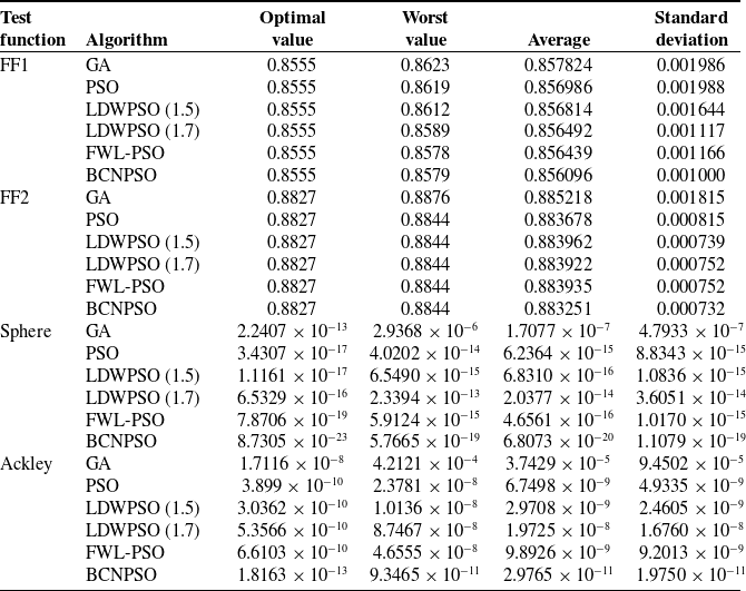
To evaluate the robustness of BCNPSO in identifying optimal shift points and other optimization problems, FF1, FF2, sphere, and Ackley were used as test functions. Each function was executed 50 times independently under identical parameter conditions, and the results are presented in Table IV.
The experimental results show that, for test function FF1, the proposed BCNPSO algorithm achieves a standard deviation of 0.00100 after 50 iterations. Compared with the standard deviations of GA (0.001986), PSO (0.001988), LDWPSO (0.001117), and FWL-PSO (0.001166) under the same number of iterations, BCNPSO yields reductions of 49.6%, 49.7%, 10.5%, and 14.2%, respectively. Furthermore, the range between the best and worst solutions obtained by BCNPSO is only 0.0024, which is smaller than that of the other four algorithms, further indicating its superior stability. When the test function was Sphere, BCNPSO achieved an average value of 6.8073 × 10⁻²⁰ after 50 runs, maintaining a significant advantage over the best-performing FWL-PSO algorithm’s 4.6561 × 10⁻¹⁶ among the other four algorithms. When the comparison function was replaced with the other two functions, the optimal value, worst value, and all four other metrics showed even better performance, fully validating its robustness.
Comparison of results from different algorithms.

Table IV. Long description
A table comparing the performance of different algorithms on various test functions. The table has 4 rows and 6 columns. Column headers are Test function, Algorithm, Optimal value, Worst value, Average, and Standard deviation. Row labels include test functions FF1, FF2, Sphere, and Ackley, and algorithms GA, PSO, LDWPSO (1.5), LDWPSO (1.7), FWL-PSO, and BCNPSO. Each row provides values for optimal, worst, average, and standard deviation for each algorithm on the respective test function. Notable trends include varying performance across different algorithms and test functions, with specific values provided for each metric.
4.3 Performance evaluation of the parking path-planning algorithm
To evaluate the proposed vertical garage parking path-planning algorithm, the initial position is set at (0, 0, 0°), and the target point is set at (1, −0.73, 90°). Simulation results are presented in Figure 10(a), where the blue curve represents the trajectory of the vehicle’s rear axle during the parking process.
Figure 10(b) illustrates the optimized trajectory obtained via nonlinear optimization, consisting of 42 discrete path points. A comparison between the optimized and unoptimized paths (Figure 10c) shows that the transition at the junction between straight segments and circular arcs is significantly smoother after optimization. As indicated in Eq. (25), curvature discontinuities lead to abrupt changes in the reference steering angle, with the magnitude of these changes reflecting the degree of curvature variation. Figure 10(d) illustrates the reference steering angle profiles before and after optimization. The nonlinear optimization yields a considerably smoother reference steering angle, thereby reducing the excitation imposed on the steering actuator.
To evaluate the flexibility of the proposed path-planning algorithm, four initial positions were selected for parking simulation experiments. The corresponding results are presented in Figure 11(a), which demonstrates that the algorithm performs effectively across a variety of starting configurations. Figure 11(b) illustrates the variation of heading angle with path length at different initial positions. This demonstrates that the proposed algorithm plans a path with a small deviation of the heading angle from the target position after parking, even with different initial heading angles, ensuring better vehicle positioning post-parking.
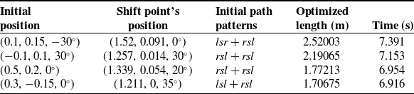
Table V presents the planning results for different initial positions. Analysis indicates that the proposed BCNPSO Reeds–Shepp algorithm can generate smooth and feasible parking paths from multiple initial positions within a short timeframe.
Path information for different initial positions.

Table V. Long description
The table presents path information for different initial positions. It has four rows and five columns. The columns are labeled Initial position, Shift point’s position, Initial path patterns, Optimized length (m), and Time (s). Row 1: Initial position (0.1, 0.15, 30), Shift point’s position (1.52, 0.091, 0), Initial path patterns lsr + rsl, Optimized length (m) 2.52003, Time (s) 7.391. Row 2: Initial position (0.1, 0.1, 30), Shift point’s position (1.257, 0.014, 30), Initial path patterns rsl + rsl, Optimized length (m) 2.19065, Time (s) 7.153. Row 3: Initial position (0.5, 0.2, 0), Shift point’s position (1.339, 0.054, 20), Initial path patterns rsl + rsl, Optimized length (m) 1.77213, Time (s) 6.954. Row 4: Initial position (0.3, 0.15, 0), Shift point’s position (1.211, 0, 35), Initial path patterns lsl + rsl, Optimized length (m) 1.70675, Time (s) 6.916.
Comparison of effects before and after optimization. (a) Initial path; (b) optimized path; (c) path comparison; (d) variation in equivalent front wheel steering angle.

Figure 10. Long description
Panel A: A visual representation of the initial path of a vehicle in a parking scenario. The vehicle is shown navigating around obstacles. Panel B: A visual representation of the optimized path of the same vehicle in the same parking scenario. The vehicle’s path appears smoother and more efficient compared to the initial path. Panel C: A line graph comparing the initial path and the optimized path. The x-axis represents the distance in meters, and the y-axis represents the position in meters. The initial path is depicted in blue, and the optimized path is depicted in red. The graph shows that the optimized path is more efficient, with fewer sharp turns and a smoother trajectory. Panel D: A line graph showing the variation in the equivalent front wheel steering angle. The x-axis represents the distance in meters, and the y-axis represents the reference steering angle in degrees. The initial path is depicted in blue, and the optimized path is depicted in red. The graph shows that the optimized path has a more consistent steering angle, reducing sharp turns and aligning more with human driving preferences.
To evaluate the path quality of the proposed BCNPSO Reeds–Shepp path-planning algorithm, comparative experiments were conducted under the same scenario with identical start and goal points. The proposed algorithm was compared with the classical Hybrid A* algorithm [Reference Dolgov, Thrun, Montemerlo and Diebel44], the Bi-RRT-Reeds–Shepp algorithm [Reference Jhang, Lian and Hao11], and the IHA-PPP algorithm [Reference Guo14].
Figure 12(a) compares parking paths generated by four algorithms. By identifying optimal shift points and corresponding Reeds–Shepp curve types via nonlinear optimization, the proposed BCNPSO Reeds–Shepp algorithm yields a smoother forward path than the three benchmarks. Moreover, during reverse parking, it achieves smaller parking deviation by integrating the garage entrance deviation into the fitness function. Figure 12(b) shows heading angle variations along the path. Unlike competing algorithms whose heading angles drift from the target after garage entry, the BCNPSO Reeds–Shepp algorithm reaches the target heading immediately upon entry and holds it until the destination. Figure 12(c) compares reference steering angles across methods. The proposed planner requires direction changes only at turning points, producing a smoother parking path than other algorithms.
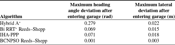
Table VI compares the four algorithms in terms of maximum heading angle and lateral deviation after garage entry. In this comparison, the proposed algorithm reduces the maximum heading angle deviation by 0.278 rad and the maximum lateral deviation by 0.019 m relative to the Hybrid A* algorithm. Furthermore, relative to the Bi RRT* Reeds–Shepp algorithm and the IHA-PPP algorithm, our BCNPSO Reeds–Shepp algorithm achieves reductions in maximum heading deviation of 0.068 and 0.07 rad, respectively, and in maximum lateral deviation of 0.012 and 0.015 m, respectively. These results demonstrate its superior post-parking positioning accuracy and lower collision risk during the parking process.
Comparison of path planning results using different algorithms.

Table VI. Long description
A table comparing the performance of different path planning algorithms. The table has four rows and three columns. The columns are labeled Algorithm, Maximum heading angle deviation after entering garage (rad), and Maximum lateral deviation after entering garage (m). The row labels are Hybrid A*, Bi RRT* ReedsShepp, IHA-PPP, and BCNPSO ReedsShepp. Row 1: Hybrid A*, 0.279, 0.022. Row 2: Bi RRT* ReedsShepp, 0.069, 0.015. Row 3: IHA-PPP, 0.071, 0.018. Row 4: BCNPSO ReedsShepp, 0.001, 0.003.
Simulation results with different initial positions. (a) Paths from different initial positions;. (b) Variation in heading angle from different initial positions.

Figure 11. Long description
Panel A: A line graph shows paths from different initial positions in a parking scenario. The x-axis represents the horizontal position in meters, ranging from -0.3 to 2.4 meters. The y-axis represents the vertical position in meters, ranging from -1.2 to 0.6 meters. Four paths are depicted, labeled as Position 1, Position 2, Position 3, and Position 4, each with distinct colors. The paths navigate around a central obstacle. Panel B: Another line graph illustrates the variation in heading angle from different initial positions. The x-axis represents distance in meters, ranging from 0 to 2.8 meters. The y-axis represents the heading angle in radians, ranging from -0.6 to 1.8 radians. Four lines, corresponding to the same positions as in Panel A, show how the heading angle changes over distance. Key heading angles are annotated, such as theta equals 1.5708 radians and theta equals -0.5236 radians.
Simulation results of different algorithms. (a) Parking path; (b) variation in heading angle; (c) variation in equivalent front wheel steering angle.

In summary, this study proposes a vertical parking path-planning method using the BCNPSO Reeds–Shepp algorithm. Shift positions and Reeds–Shepp curve profiles are optimized via BCNPSO, followed by nonlinear optimization to ensure curvature continuity. A fitness function based on parking requirements is optimized using an improved particle swarm algorithm, whose optimality and convergence are validated in Section 4.2.2. After obtaining optimal shift points, the path is generated with two Reeds–Shepp segments. Given initial and target poses, the shortest collision-free path is selected. Since each valid combination yields a unique solution, this combinatorial strategy ensures the overall path planning algorithm’s optimality and convergence.
4.4 Real vehicle test
The experimental platform is based on an intelligent automated guided vehicle (AGV), as presented in Figure 13(a). The vehicle is designed with an Ackermann-type steering mechanism, in which the front wheels govern steering while the rear wheels deliver propulsion. Continuous modulation of the front-wheel steering angle enables directional control, whereas the rear wheels remain in a state of pure rolling, aligned parallel to the longitudinal axis of the chassis. The correspondence between turning radius and travel speed conforms to the Ackermann steering geometry. Furthermore, the AGV is integrated with a Lidar sensor, an inertial measurement unit (IMU), and an embedded Jetson Nano computing module, which together furnish the requisite hardware foundation for autonomous parking path planning. The mass of the vehicle is 5 kg, and all remaining key parameters are consistent with those in the simulation model. Detailed parameters are provided in Table II.
To account for potential wheel slippage during vehicle motion, the width of the vertical parking space in the simulated map was extended by 0.5 m, with all other parameters held constant. The updated layout is illustrated in Figure 13(b). Based on the data presented in Table II, the vehicle exhibits a length-to-width ratio of 1.428, whereas the parking space has a corresponding ratio of 1.24. Specifically, the vehicle length occupies 80% of the garage length, and its width accounts for 70% of the garage width. This configuration reflects a typical and challenging real-world scenario, offering a representative operational environment for evaluating autonomous parking maneuvers.
Experimental platform and test field. (a) Experimental platform; (b) Test field.

To execute the parking maneuver, the longitudinal velocity was set to 0.1 m/s for forward motion and –0.1 m/s for reverse motion. A pure pursuit controller [Reference Coulter45] was employed for trajectory tracking. The initial position is given as (0, 0, 0°), and the target position is (1, −0.73, 90°). The parking process in the real scenario is shown in Figures 14 and 15.
Forward movement. (a) State 1 in a real-world scenario; (b) State 2 in a real-world scenario; (c) State 3 in a real-world scenario; (d) visualization of State 1; (e) visualization of State 2; (f) visualization of State 3.

Backward movement. (a) State 1 in a real-world scenario; (b) State 2 in a real-world scenario; (c) State 3 in a real-world scenario; (d) visualization of State 1; (e) visualization of state 2; (f) visualization of State 3.

Figure 15. Long description
The image consists of six panels: three photos and three diagrams. Panel A: A photo showing a vehicle in the initial state of a parking scenario, positioned at the entrance of a parking spot. Panel B: A photo showing the vehicle in the second state, partially parked within the spot. Panel C: A photo showing the vehicle in the final state, fully parked within the spot. Panel D: A diagram visualizing the initial state of the vehicle, with a green line representing the path taken. Panel E: A diagram visualizing the second state of the vehicle, with a green line representing the path taken. Panel F: A diagram visualizing the final state of the vehicle, with a green line representing the path taken. The diagrams show the vehicle’s movement and path planning in a structured parking scenario.
As illustrated in Figure 16(a), the trajectory of the rear axle center remains within a reasonable margin of error relative to the reference path shown in Figures 13 and 14, demonstrating the successful completion of the perpendicular parking task. Figure 16(b) presents the variation in front wheel steering angle with respect to driving distance, confirming that the parking maneuver was executed within the allowable steering angle limits. Furthermore, Figure 16(c) shows the evolution of the vehicle’s heading angle over distance; the heading angle remains stable after entry into the parking space, thereby validating the final orientation of the vehicle.
Experimental results in real-world scenarios. (a) Comparison between the actual path and the reference path; (b) change in steering angle; (c) change in heading angle.

The lateral and heading errors during the parking maneuver are presented in Figure 17(a) and (b), respectively. The lateral tracking error peaks at 0.013 m, indicating precise path following within a tight tolerance, while the heading angle error settles at 0.012 rad at the endpoint, confirming the vehicle’s ability to achieve the desired final orientation.
Path-tracking errors in real-world scenarios. (a) Lateral error during tracking; (b) heading error during tracking.

To evaluate the flexibility of the BCNPSO Reeds–Shepp parking path-planning algorithm, the initial pose of the vehicle was set to (0.1, 0.15, –30°), while the destination remained unchanged. The trajectory tracking results are shown in Figure 18(a). The results demonstrate that the vehicle successfully completed the parking task under this starting configuration. Figure 18(b) presents the lateral tracking error curve during parking. Lateral error analysis reveals minimal deviation throughout the process, with a maximum error of 0.011 m for this configuration. As illustrated in Figure 18(c), the heading angle error remains within an acceptable range, peaking at 0.105 rad despite a nonzero initial condition. In summary, the proposed path-planning algorithm exhibits strong adaptability and robustness to variations in initial poses, confirming its feasibility and effectiveness in parking scenarios.
Parking process with an initial pose of (0.1, 0.15, −30°). (a) Comparison between the actual path and the reference path; (b) lateral error during tracking; (c) heading error during tracking.

Figure 18. Long description
Panel A: A line graph compares the actual path and the reference path during a parking process. The x-axis represents the X coordinate in meters, ranging from 0 to 2. The y-axis represents the Y coordinate in meters, ranging from -1 to 0.6. The actual path is shown in red, while the reference path is shown in blue. The graph illustrates the vehicle’s trajectory as it navigates through a parking scenario. Panel B: A line graph displays the lateral error during tracking over time. The x-axis represents time in seconds, ranging from 0 to 24. The y-axis represents the lateral error in meters, ranging from -0.012 to 0.006. The graph shows fluctuations in the lateral error as the vehicle attempts to follow the reference path. Panel C: A line graph shows the heading error during tracking over time. The x-axis represents time in seconds, ranging from 0 to 24. The y-axis represents the heading error in radians, ranging from -0.10 to 0.10. The graph illustrates variations in the heading error as the vehicle aligns its direction with the reference path.
5. Conclusion
To address the challenges of strict initial position constraints, insufficient clearance between the path and garage boundaries, and discontinuous curvature in traditional path planning for vertical parking scenarios, this paper presents a novel vertical parking path-planning method based on the Reeds–Shepp curve and an Improved Particle Swarm Optimization algorithm. The main conclusions are as follows:
(1) By segmenting the vertical parking process into two distinct phases and using the Reeds–Shepp curve to plan the path separately, the flexibility of path planning from various initial positions is enhanced. The shift point is treated as a position variable in the particle swarm algorithm, using the deviation during garage entry and path length as the fitness function. After determining the optimal shift point with the improved algorithm, the path is formed by two Reeds–Shepp curve segments, effectively addressing the proximity issue to the garage boundary upon parking completion. (2) By discretizing the paths derived from two Reeds–Shepp curves and solving a formulated constrained nonlinear optimization problem, the issue of curvature discontinuity at the junctions can be effectively addressed. (3) Through multiple experimental sets, the proposed perpendicular parking path-planning method demonstrated its ability to generate feasible paths from various initial locations. Compared to the Hybrid A* algorithm, it reduced the maximum heading angle deviation after garage entry by 0.278 rad and the maximum lateral deviation by 0.019 m. Compared to the Bi RRT* Reeds–Shepp algorithm [Reference Jhang, Lian and Hao11] and the IHA-PPP algorithm [Reference Wang and Gu15], the proposed BCNPSO Reeds–Shepp algorithm also exhibited lower deviations. The feasibility of the generated paths was validated through real-vehicle experiments, offering a novel reference solution for perpendicular parking path planning.
Although the proposed algorithm has been validated in simulated parking environments, the path-planning algorithm presented in this paper relies on positioning accuracy. In future research, we will deepen our investigation into high-precision positioning technologies and try to deploy the planning algorithm in outdoor parking lots that more closely resemble real-world scenarios to further validate its practical effectiveness.
Author contributions
Guangqi Hu: proposed the research idea and designed the study. Likun Cui: funding acquisition, project administration, writing, review, and editing. Hao Wang: validation of correlation algorithms. Guangqi Hu: completed the manuscript writing. Xinle Li: reviewed and refined the paper.
Financial support
This research is supported by the Natural Science Foundation of Shaanxi Province (Grant No. 2023-JC-YB-018).
Competing interests
The authors declare no conflicts of interest exist.


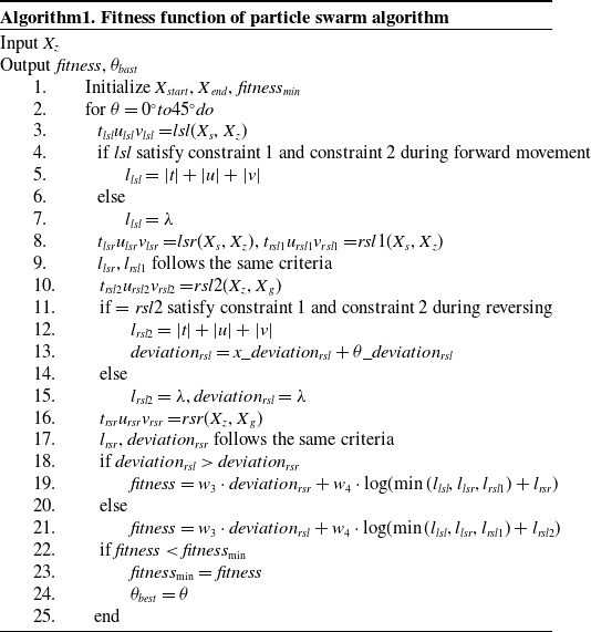

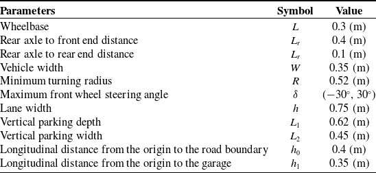


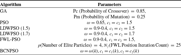

 λ