Introduction
In the current rapidly changing industrialized world based on globalization, product customization, and automation, the manufacturing industry is playing an imposing role. The manufacturing industry is on the top of Industry 4.0 because it brings with it advanced technologies and techniques capable of rapidly and efficiently changing the products, processes, and supply chains involved in every aspect of the industry. This technology ushers in even greater connectivity that will allow manufacturers to maintain their competitive edge in a rapidly changing world and responds flexibly and quickly to customers’ requirements (4th Industrial Revolution called Industry 4.0). Manufacturing metrology is an integral part of the advanced manufacturing system based on Industry 4.0 because almost everything that has been machined needs to be measured or inspected on some of the metrological systems. Industry 4.0 is characterized by high-level methodologies for the development of new generation manufacturing metrology systems, which are more intelligent (smart), autonomous, flexible, interoperable, high-productive, and self-adaptable. One of the systems that is capable of responding to these challenges is a cyber-physical manufacturing metrology system (CP2MS).
According to Berthold and Imkamp (Reference Berthold and Imkamp2013), in the manufacturing sector, in metrology context, there are three areas where Industry 4.0 will provide support: (a) smart supply chains (cyber-physical metrological traceability); (b) smart manufacturing (cyber-physical metrology in manufacturing); and (c) smart products (intelligent metrology).
Based on PTB's approach (Metrology for the Digitalization, 2017) in a digital era, the following new key points have been determined:
a) digital transformation of metrological services;
b) analysis of large quantities of data;
c) communication systems for digitalization;
d) simulations and virtual measuring instruments; by developing analytical methods and procedures for interconnected and virtualized measuring systems, the simulation of complex measuring systems for the planning and analysis of experiments, procedures and measurement standards for automated process control and virtual measurement processes for the automatic assessment of measured data is actively supported.
According to the above-mentioned classification, our indirect contribution to the framework of Industry 4.0 development involves simulations and virtual measurements and inspection (as given under d)) of prismatic parts on a coordinate measuring machine (CMM). The classification can be complemented by genetic algorithm (GA)- and ant-colony optimization (ACO)-based optimization, as also supported by the model developed in this paper.
According to Lazzari et al. (Reference Lazzari, Pou, Dubois and Leblond2017), smart metrology is the implementation of a revised metrological function to make relevant decisions using artificial intelligence (AI) techniques. The thus major novelty and contribution of the paper is the development of a new metrological model [cyber-physical manufacturing metrology model (CP3M)] for smart metrology within an Industry 4.0 framework. In a broad sense, this model represents a new approach that should respond to the requirements prescribed by Industry 4.0 in terms of metrology: intelligent (smart), autonomous, flexible, interoperable, high-productive, and self-adaptable. In a narrow sense, by applying AI techniques (ACO and GA), the model fully generates the shortest measuring path for the optimal number of prismatic measurement parts (PMPs) setups and the optimal number of probe configurations.
If it is known that in measurements on a CMM, the measuring path length is directly proportional to time, mentioned optimizations reduce measuring time, thus increasing work productivity on a CMM in inspection planning phases and measurements execution. On the other hand, CP3M automatically generates measuring path, eliminating operator's intuition and experience to a large extent, which is in the context of Industry 4.0 one of the prerequisites for its (CP3M) successful application.
However, the forerunner of the development of a model to fulfill these requirements in compliance with Industry 4.0 implies a brief look at the facts and current real problems in the realm of inspection planning on a CMM. Elimination of these problems paves the way to the development of a cyber-physical system for Industry 4.0.
As it is known, inspection performance on measurement machines is based on complex software support for various classes of metrological tasks (tolerances). Implementation of uniform inspection planning for such machines is a special problem that depends on the metrological complexity of prismatic parts, inspection planner's intuition, and experience-based knowledge. Elimination of intuition, presentation of knowledge, reuse and share of knowledge through the development of CP3M based on an intelligent system for inspection planning capable of decision-making at a given moment, is a solution of the mentioned problem. In developing the intelligent system, the emphasis is placed on generating the optimal measurement sensor path as a fundamental segment of prismatic parts inspection.
In all todate authors’ investigations on the development of an intelligent system for inspection planning of PMPs on a CMM (Stojadinovic and Majstorovic, Reference Stojadinovic and Majstorovic2014; Stojadinovic et al., Reference Stojadinovic, Majstorovic, Durakbasa and Sibalija2016a, Reference Stojadinovic, Majstorovic, Durakbasa and Sibalija2016b), a detailed methodology was developed to obtain an optimal measuring path for a single, a priori known, part setup and probe configuration. In order to take into account all possible part setups and probe configurations, it is needed to perform new investigations, i.e., the analysis of part setup and probe configuration, and thereafter by applying GA to reduce a set of possible solutions to optimal solution. Two sets of information play a key role in the analysis, and these are data on PMP geometry and tolerances.
In creating a measuring protocol, the measurement part geometry is taken into account, or the CMM programming software is entered in the form of some output files such as neutral data format, initial graphics exchange specification (IGES), or standard for the exchange of product data (STEP), while data on tolerances are entered from a technical drawing. For now, there is no data format or file, where both data on geometry and data on tolerances are stored. Some computer-aided design (CAD) software systems, such as Autodesk Inventor Professional 2015 or Catia V5, are capable of specifying, in a 3D environment, some forms of tolerance such as tolerances of length and diameters. However, data format that reveals the relationship between specified tolerances and part geometry which is involved in creating a given tolerance does not exist for now. This problem makes considerably hard the development of CP3M based on an intelligent approach of probe configuration and setup planning for inspection of PMPs on a CMM due to the division of a set of information required.
According to Zhao et al. (Reference Zhao, Xu, Kramer, Proctor and Horst2011), the major problems occurring in the process of defining the product and measurements are:
• geometric dimensioning and tolerance (GD&T) data must be modeled within the CAD data, but not given as comments or records. ISO 10303 application protocol (AP) 224 (feature-based representation) incorporates a model of tolerance features, but as such is not supported by CAD systems for now;
• currently, one of the major supports for standard development is a new version of ISO 10303 AP 203 which models tolerance elements. Further harmonization of GD&T definitions should be done between AP 214 (data core for automatic machine processes design) and AP 224, and their adoption in AP 203. It is only in this way that it will be possible for AP 203 to ensure adequate information for generating the measurement process planning;
• nonstandard GD&T information related to the design of a part geometry;
• the absence of computer-readable (interpretative) and standard definitions of resource possibilities of measuring equipment, capacity, possible configuration, performances, etc.
One of the early solutions for the mentioned problems is viewed in the development of expert systems (ElMaraghy and Gu, Reference ElMaraghy and Gu1987), and later in the development of an automatic inspection model with the GD&T elements (Limaiem and ElMaraghy, Reference Limaiem and ElMaraghy1998; Yau and Menq, Reference Yau and Menq2005; Chang and Lin, Reference Chang and Lin2010, Reference Chang and Lin2011; Ravishankar et al., Reference Ravishankar, Dutt and Gurumoorthy2010; Hussien et al., Reference Hussien, Youssefy and Shoukryz2012; Zhao et al., Reference Zhao, Kruth, Gestel, Boeckmans and Bleys2012).
One approach to defining the products and measurements can be feature-based and is presented in Zhang et al. (Reference Zhang, Ajmal, Wootton and Chisholm2000). Each simple or compound feature may be one of the several types identifying several joint features in the measurement process planning – such as cones, cylinders, and features composed-like patterns (repetitive elements). Mentioned problems directly affect the realization of interoperability inside of CP2MS and hinder the development of automatic and intelligent concept of inspection on a CMM. An attempt to point to the importance of solution to these problems is presented in Osanna (Reference Osanna1997) and Germani et al. (Reference Germani, Mandorli, Mengoni and Raffaeli2010), and the development of an intelligent inspection planning system based on object-oriented programming is shown in Roy et al. (Reference Roy, Xu and Wang1994). The solution of mentioned problem is noticeable in the decomposition of a measurement part into geometric features and definition of their association with a certain form of tolerance in a unique ontology database. The basic task of a database is to give metrological features at the output, that is, relationships between geometric features and tolerances for measurement part. Integration of geometry and tolerances as a prerequisite for realization of investigations in the present paper was carried out using already developed ontology database of knowledge given in Stojadinovic and Majstorovic (Reference Stojadinovic and Majstorovic2012) and Majstorovic et al. (Reference Majstorovic, Stojadinovic and Sibalija2015).
Mentioned problems create a gap between geometry and PMP tolerances and affect the automatic generation of information for the CP2MS measurement process planning.
Besides Introduction and Conclusion, the paper consists of six chapters.
The second chapter analyzes an Industry 4.0 concept and manufacturing metrology framework for it.
The third chapter analyzes the measurement part setup in order to achieve the minimum number of part setups, along with fulfilling technological measuring conditions. The analysis was carried out based on geometric features that PMPs consist of in terms of tolerances and definition of approach directions for them.
In the fourth chapter, a new configuration model is presented for two forms of probes, probe star and probe head. In a general case, five probes, with different orientations, can be set up in a measurement sensor carrier. The GA application in this context requires decomposition of the general case for a probe star and coding of each separate case. On the other hand, the application of GA for probe head configuration enables its modeling as an industrial manipulator with 2 degrees of freedom (DOFs).
In the fifth chapter, a modified optimization algorithm was applied (Rice and Nyman, Reference Rice and Nyman2013), based on GA. The result of carried out optimization (algorithm) is a new methodology of the analysis of PMP setup and probe configuration for each of the setups. The algorithm was tested on a single PMP and results are shown.
In the sixth chapter, experimental verification of a developed inspection planning model was done and results are given. For the purpose of path verification and simulation to visually check the collision between measurement sensor and PMP, first a program was written in the MatLab software environment. In addition to verification and simulation, one of the major goals of the written program is to generate the measuring protocol and program code at the output, which are thereafter used as the input for experimental measurements.
Industry 4.0 concept and manufacturing metrology framework
The nine pillars and forty-two elements of Industry 4.0 will transform isolated and optimized manufacturing cells into a fully integrated, automated, and optimized manufacturing and measurement flow, leading at the same time to greater efficiency and change in traditional manufacturing and measurement relationships among suppliers, producers, and customers as well as between human and machine (Majstorovic et al., Reference Majstorovic2019).
Industry 4.0 defines a methodology to generate a transformation from machine dominant manufacturing (metrology) to digital manufacturing (metrology) (Berthold and Imkamp, Reference Berthold and Imkamp2013), by cyber-physical systems (CPS), cloud system, Big data and data mining, machine to machine interfaces, enterprise resource planning and Business intelligence, Internet of Things (IoT), augmented reality, simulation, virtual manufacturing, and intelligent robotics. All those elements include different levels of manufacturing activities.
Investigations conducted in this paper primarily fill the gap in Industry 4.0 and its smart metrology component. As it is well-known, Industry 4.0, among other things, requires high-level intelligence, automation, productivity, and autonomy in smart manufacturing, demanding from smart metrology to follow that level. Also, the tendency of Industry 4.0 is green production, that is, optimization of resources and time. One of the major contributions of the paper is higher level of intelligence (by applying EO, GA, and ACO), autonomy (tendency toward elimination of man), and productivity (reduction of total measuring time in the measurement execution phase) realized through optimization and automatic setup of measurement parts and probe configuration.
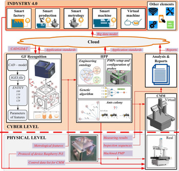
A framework of CP3M model is presented in Figure 1 and includes two basic components: physical and cyber. The overall model consists of the following sub-modules: (a) module for definition and recognition of geometrical features (GFs) from CAD/GD&T model of the measurement part, where we used them for definition of metrological feature, (b) module for building of intelligent inspection process planning (IIPP) based on AI techniques (EO, GA, and ACO) and a method for part setup and configuration of probes, (c) CMM module receives data from IIPP such as control data list for physical CMM and inspection sequence for virtual CMM, and (d) module for analysis and reports of generation of the final measuring reports for cloud. Cloud services, u in this context, provide transfer of the necessary information for integration of knowledge and data between cyber and Industry 4.0 level.
CP3M framework for Industry 4.0 (adapted from Majstorović et al. (Reference Majstorović, Stojadinovic, Zivkovic, Djurdjanovic, Jakovljevic and Gligorijevic2017)).

As it can be seen from Figure 1, the need or Industry 4.0 is at the top level, which involves smart metrology with its features such as intelligent, autonomous, and productive. It is also evident that the bottom level includes measurements of execution and a real CMM. The link between Industry 4.0 and a real CMM is the developed CP2MS. The major component of CP2MS is IIPP and within it part setup and probe configuration.
GF recognition module recognizes GFs from the 3D model of measurement part in a neutral CAD format, such as IGES. The role of the IIPP module is to generate inspection sequence for probe configurations that CMM supports. It has GFs and tolerances at the input. During the inspection sequence generation, it is necessary to extract metrological features from GFs. The metrological, as well as the GFs, depends on the type of measuring part and the applied standards. If necessary, the application for metrological features extraction should be provided to the IIPP module.
Part of the link (Fig. 1) or protocols inside CP3M was taken over from standards G&DT, AP i IGES, and another part was developed by the authors: control data list for ZEISS CMM, parameters of metrological features, and inspection sequence. A special problem is the fact that each CMM manufacturer has its own software for programming measuring paths, which requires the development of a new protocol for each of them. At present, we have developed the protocol for ZEISS of this machine and software they are using. Future investigations involve plans to do it for other manufacturers. Also, future investigations involve the development of our own protocol between cloud and Industry 4.0 technologies based on Big data analytics.
Realization of the CP3M, in practice, is being investigated for the ZEISS CMM, which is based on the IoT cloud technology. Connection of the physical and the cyber world is provided using an IoT device – Raspberry Pi3, which, via industrial router, has access to the Internet and realizes direct communication with the CMM control unit, using ethernet or wifi connection.
Analysis of PMPs setup for CP3M
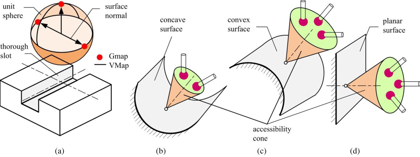
The analysis of PMPs setup and probe configuration for CP3M is mainly integrated into accessibility analysis (Limaiem and Maraghy, Reference Limaiem and Maraghy1997; Ziemian and Medeiros, Reference Ziemian and Medeiros1997, Reference Ziemian and Medeiros1998; Jackman and Park, Reference Jackman and Park1998; Chiang and Chen, Reference Chiang and Chen1999; Spitz et al., Reference Spitz, Spyridi and Requicha1999; Rico et al., Reference Rico, Valino, Mateous, Cuesta and Suarez2002; Wu et al., Reference Wu, Liu and Zhang2004; Alvarez et al., Reference Alvarez, Fernandez, Rico, Mateos and Suarez2008). If viewed disintegrated, the basic difference is in that the analysis of setup is PMP-oriented, whereas the accessibility analysis is PMP-feature-oriented. In other words, for each PMP setup, it is necessary to conduct accessibility analysis and based on it to configure the probes. Accessibility analysis is founded on approach directions that belong to the forms such as a sphere (Fig. 2a) and cone (Fig. 2b–d).
Local feature accessibility: (a) sphere for thorough slot (GMap i VMap), (b) cone for concave surface, (c) cone for convex surface, and (d) cone for planar surface (adapted from Limaiem and Maraghy (Reference Limaiem and Maraghy1997) and Spitz et al. (Reference Spitz, Spyridi and Requicha1999)).

For an ideal PMP, whose shape corresponds to a cuboid, the maximum number of setups equals the number of cuboid sides, that is, six. Setup of parts with irregular shape was considered by Lai and Chen (Reference Lai and Chen2007). Accessibility analysis was also considered by Lim and Menq (Reference Lim and Menq1994) for the purpose of generating the measuring path.
The goal of analysis setup in this chapter is to support the development of CP3M for the needs of Industry 4.0 and to satisfy technological measurement conditions (measurement bases, etc.), minimum number of measurement part setups, optimal probe configuration (minimum number of probes, etc.). This segment of CP3M automatically defines inspection sequences per PADs for a workpiece.
Mathematical model
Mathematical model of a PMP setup should be built for defining a general matrix of the PMP setup, depending on the number of its features, and for applying GA technique afterwards (Stojadinovic and Majstorovic, Reference Stojadinovic and Majstorovic2019). The model is based on metrological and GFs used to analyze setups and define the approach directions.
Geometric and metrological features
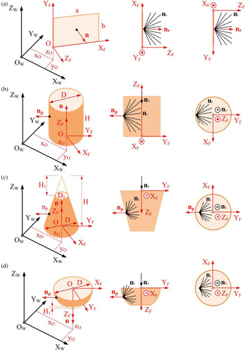
GF is a basis for the analysis of the measurement sensor probes accessibility, measurement sensor configuring, path planning, and generation of the measuring protocol for input measuring requirements. From the viewpoint of metrology, a single metrological feature consists of one or more than one GFs. In our inspection planning model, the GFs represent the lowest level of defining tolerances or objects of generating measurement sensor points. GFs such as plane, sphere, and cone, are used to generate and describe all types of geometric features. Each GF is unambiguously determined by a set of parameters relative to the local coordinate system (OF, XF, YF, ZF) and measurement coordinate system of the measurement part (OW, XW, YW, ZW). According to Stojadinovic et al. (Reference Stojadinovic, Majstorovic, Durakbasa and Sibalija2016a), parameters can be of the following types: coordinates (X, Y, Z), diameter (D, D 1), height (H, H 1), width (a), length (b), feature vector (n), feature fullness vector (np), global approach direction (nG), and local approach direction (nL). All mentioned coordinate systems, as well as parameters and vectors, are shown in Figure 3. Extraction of parameters and feature vectors from some of the CAD output files, most often STEP and IGES, is possible based on knowledge of the structure of files records.
Basic geometric features with parameters and defined local and global approach directions: (a) plane, (b) cylinder, (c) truncated cone, (d) truncated hemisphere (Stojadinovic and Majstorovic, Reference Stojadinovic and Majstorovic2019).

The primary goal of parametric definition of the features is to unambiguously decompose PMP into GFs that indirectly, through tolerances, take part in inspection planning.
As mentioned in the Introduction section, for now the software systems for CAD modeling have the capacity to enter only a limited number of form tolerances. This fact indicates that the CAD model of a part in the inspection planning process can be used only from the viewpoint of geometry and partially from the viewpoint of tolerances. For that reason, the PMP geometry and its tolerances are linked in this CP3M based on developed ontological basis as presented in Majstorovic et al. (Reference Majstorovic, Stojadinovic and Sibalija2015).
Approach directions for PMPs
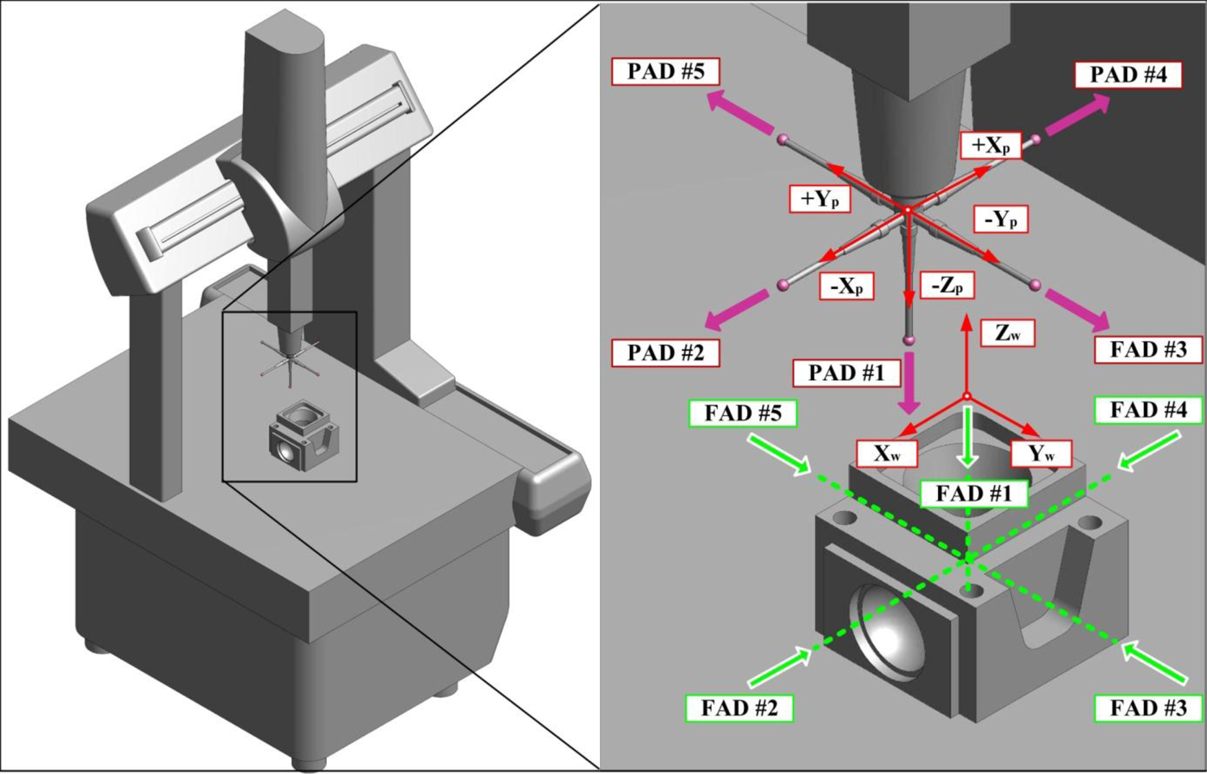
Inspection planning for PMPs on a CMM, depending on the number, position, and orientation of probes setup in a measurement sensor, is mainly performed from three mutually orthogonal directions (axes) corresponding to a Cartesian coordinate system. This assumption is used as a basis for developing a probe configuration and PMPs setup for CP3M. According to Stojadinovic and Majstorovic (Reference Stojadinovic and Majstorovic2019) from mentioned three directions, it is possible to derive five potential probe approach directions (PAD: PAD #1, PAD #2, PAD #3, PAD #4, and PAD #5) (Fig. 4).
Feature approach directions (FADs) and probe configuration approach directions (PADs).

Each of these directions has a direction corresponding to some of the CMM coordinate system directions. At the level of a single geometric feature, PAD is determined by vectors np and n or nG. A special case is when the direction of the vector n does not coincide with any of the mentioned PADs. Then, the probe motion is decomposed into the motion of two PADs.
From the standpoint of setup, the feature approach direction (FAD) is defined as a potential approach direction for a feature. It holds for FAD that it has the same direction as the PAD but opposite orientation.
Based on mentioned approach directions, a general form of matrices for the measurement part setup according to Stojadinovic and Majstorovic (Reference Stojadinovic and Majstorovic2019) is defined as,
 $$S = \lsqb {S_{ij}} \rsqb _{m \times n} = S_{\lpar i\comma j\rpar } = S_{ij} \quad \lpar {\lpar {i\comma \;j} \rpar \in \lcub {1\comma \;2\comma \;\ldots \comma \;m} \rcub \times \lcub {1\comma \;2\comma \;\ldots \comma \;n} \rcub } \rpar,$$
respectively,
 $$S = \left[{\matrix{ {s_{11}} & {s_{12}} & \cdots & {s_{1n}} \cr {s_{21}} & {s_{22}} & \cdots & {s_{2n}} \cr \vdots & \vdots & \ddots & \vdots \cr {s_{m1}} & {s_{m2}} & \cdots & {s_{mn}} \cr } } \right],$$
where m is the number of features for inspection and n = 6 is the number of possible directions setup for an ideal PMP.
Matrix (1) has the form of the Boolean matrix for whose elements (s ij ∈ {0, 1}) it holds:
• s ij = 1 – feature can be approached from the corresponding FAD,
• s ij = 0 – feature cannot be approached from the corresponding FAD.
This manner of matrix definition for PMP setup encompasses a real fact that one feature can be approached from several FADs, which will be definitely used later in obtaining optimal probe configuration for selected PMP setup.
Matrix setup for test PMP is given by the following expression:
 $$S = \left[{\matrix{ 1 & 0 & 1 & 0 & 1 & 0 \cr 1 & 0 & 0 & 1 & 0 & 0 \cr 1 & 0 & 0 & 0 & 0 & 0 \cr 1 & 0 & 0 & 1 & 0 & 0 \cr 0 & 0 & 1 & 0 & 0 & 0 \cr 0 & 0 & 1 & 0 & 0 & 0 \cr 0 & 0 & 1 & 0 & 0 & 0 \cr 1 & 0 & 1 & 0 & 1 & 0 \cr 1 & 0 & 0 & 0 & 0 & 0 \cr 1 & 0 & 0 & 0 & 0 & 0 \cr 0 & 0 & 1 & 0 & 0 & 0 \cr 1 & 0 & 0 & 0 & 0 & 0 \cr 1 & 0 & 0 & 0 & 0 & 0 \cr 1 & 0 & 0 & 0 & 0 & 0 \cr 1 & 0 & 0 & 0 & 0 & 0 \cr 1 & 0 & 0 & 0 & 0 & 0 \cr } } \right].$$
Probe configuration for CP3M
As above mentioned, for PMP setup on a CMM granite table, there are five PADs. The goal of the probe configuration for CP3M is the optimal probe configuration for each part setup based on possible PADs.
As it is known two types of finish measuring instruments are commonly used in inspection for PMPs on a CMM and, therefore, is configuration model divided into probe configuration of the probe star and probe head.
A general form of probe configuration matrices according to Stojadinovic and Majstorovic (Reference Stojadinovic and Majstorovic2019) is defined as,
 $$C = \lsqb {C_{ij}^{} } \rsqb _{m \times e} = C_{\lpar i\comma j\rpar } = C_{ij} \quad \lpar {\lpar {i\comma \;j} \rpar \in \lcub {1\comma \;2\comma \;\ldots \comma \;m} \rcub \times \lcub {1\comma \;2\comma \;\ldots \comma \;e} \rcub } \rpar,$$
respectively,
 $$C = \left[{\matrix{ {c_{11}} & {c_{12}} & \cdots & {c_{1e}} \cr {c_{21}} & {c_{22}} & \cdots & {c_{2e}} \cr \vdots & \vdots & \ddots & \vdots \cr {c_{m1}} & {c_{m2}} & \cdots & {c_{me}} \cr } } \right],$$
where e = (n – 1) is the total number of possible configurations.
Matrix (3) has also the form of the Boolean matrix for whose elements (c ij ∈ {0, 1}) it holds:
• c ij = 1 – probe can perform inspection from the corresponding PAD direction,
• c ij = 0 – probe cannot perform inspection from the corresponding PAD direction.
Probe star as the measurement sensor
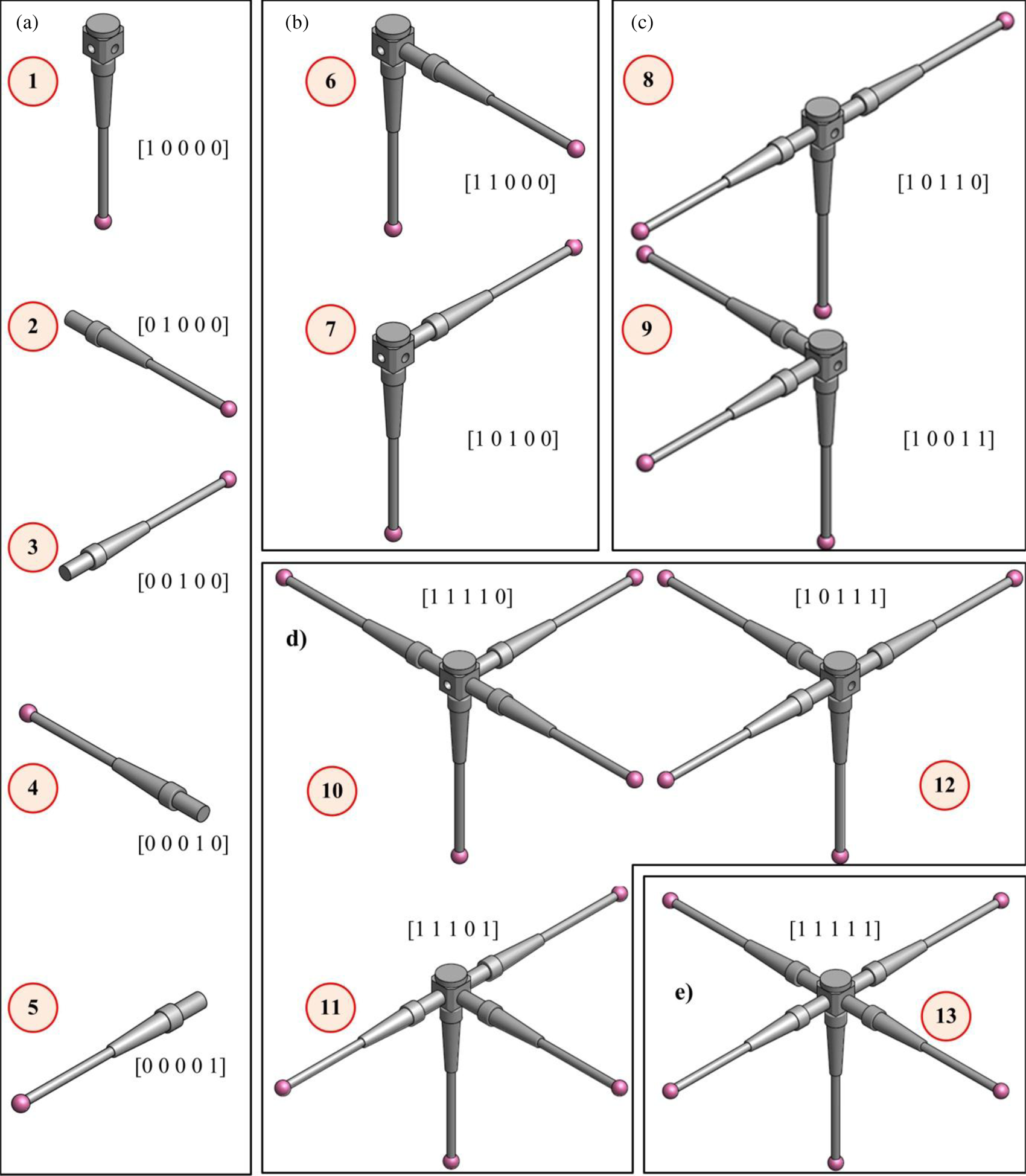
As it is known, five probes with different orientations can be set up in the measurement sensor on a CMM. Configuring of the probe for the purpose of inspection planning and measurement should involve different probe orientations in the measurement sensor carrier, which requires decomposition of the star general case and coding of each case separately. The thus obtained code represents one of the syllables of the GA population in the process of obtaining optimal configuration for a given PMP setup. A code possesses five digits (e = 5), which can be c ij ∈ {0, 1}. The number of digits in a code equals the number of possible PADs.
Examples of coding for the case of one, two, three, four, and five probe configuration is demonstrated in Figure 5.
Examples of codes of possible probe configuration for the case of using (a) one, (b) two, (c) three, (d) four, and (e) five probes (adapted from Stojadinovic and Majstorovic (Reference Stojadinovic and Majstorovic2019)).

Probe head as the measurement sensor
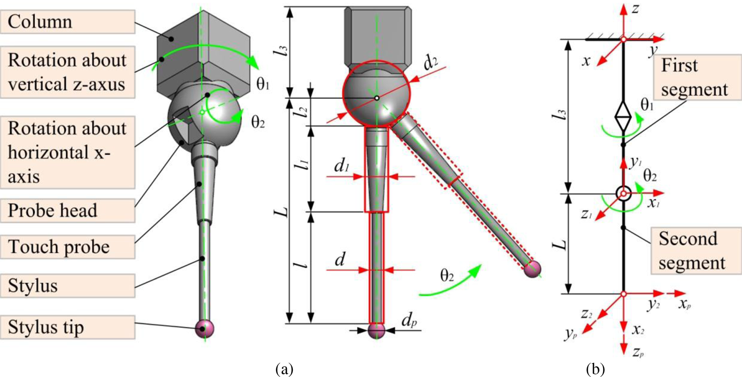
A probe head model is presented in Figure 6a. According to Stojadinovic and Majstorovic (Reference Stojadinovic and Majstorovic2019), the head is modeled like an industrial manipulator with 2 DOFs (rotations α and β) as shown in Figure 6b. In order to arrive at the measurement sensor coordinate system depending on the tip position (rubidium sphere) and probe orientation of the head itself, a kinematic problem should be solved using Denavit–Hartenberg parameters (Table 1) and their algorithm of the manipulator segments coordinate systems adopted.
Simplified probe head model: (a) 3D model and (b) line model.

Denavit–Hartenberg parameters of segments (Stojadinovic and Majstorovic, Reference Stojadinovic and Majstorovic2019)

Manipulator consists of two segments labeled 1 and 2. Segments coordinate systems are, respectively, O 0, X 0, Y 0, Z 0-zero, O 1, X 1, Y 1, Z 1-coordinate system of 1st segment, O 2, X 2, Y 2, Z 2-coordinate system of 2nd segment, and O p, X p, Y p, Z p-coordinate system of the probe tip. Matrices determining segments position and orientation are  ${}_1^0 A$ and
 ${}_2^1 A$.


Position and orientation of 2nd segment relative to zero segment are determined by the following matrix:

Probe tip position and probe orientation relative to 2nd segment are determined by the following matrix:

Probe tip position and probe orientation relative to zero segment are determined by the following matrix:

After matrix (8) is obtained, a setup mathematical model and a probe configuration model can be integrated into a mathematical model of path planning, as presented by Stojadinovic et al. (Reference Stojadinovic, Majstorovic, Durakbasa and Sibalija2016a). The aim of integration is to complete an intelligent path planning system for PMP on a CMM in such a way so that both PMP setup and probe configuration are taken into account.
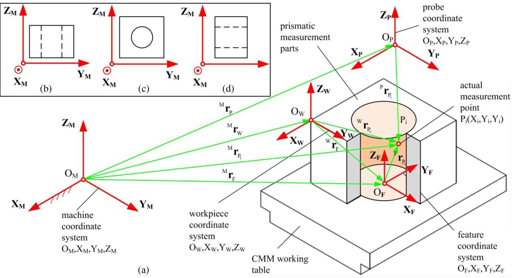
Integration is done using matrix  ${}_F^M T$ from Stojadinovic et al. (Reference Stojadinovic, Majstorovic, Durakbasa and Sibalija2016a), which defines feature position and orientation relative to the measurement machine coordinate system (CS):

where  ${}_W^M T$ is the matrix defining PMP position and orientation relative to the measurement machine CS and
 ${}_F^W T$ that defines feature position and orientation relative to the workpiece CS or PMP.
In a general case, matrix  ${}_F^M T$ is a variable for the set of possible setups and includes the entire set (number) of PMP setups. Furthermore, a set of possible setups makes matrix
 ${}_W^M T$ variable due to change of the workpiece CS position and orientation, and thereby the matrix
 ${}_F^M T$ too, due to change of the feature CS position and orientation. However, matrix
 ${}_F^W T$ remains unchanged, with the condition that there is no change of the workpiece CS. This can be explained based on Figure 7, where a set of possible setups for a given PMP is presented. The mathematical model developed by Stojadinovic et al. (Reference Stojadinovic, Majstorovic, Durakbasa and Sibalija2016a) takes into account a single setup (Fig. 7a) and describes measuring path for it using the below equation:
 $${}^M{\mathbf\,{r}}_{P_i} = \lpar x_{\rm MF} + x_{{\rm FP}_i}\rpar \overrightarrow i + \lpar y_{\rm MF} + y_{{\rm FP}_i}\rpar \overrightarrow j + \lpar z_{\rm MF} + z_{{\rm FP}_i}\rpar \overrightarrow k .$$
The developed setup and configuration model, as part of CP3M, extend the given model to a general set of setups and configurations, which is given in Figure 7b–d for this PMP, so that based on relation (10), the measuring path can be automatically defined for each new setup. Using the algorithm to be presented in the next chapter, a general set is reduced to the optimal number of PMP setups and probe configurations. The extended mathematical model has created conditions for applying GA as an optimization technique to obtain a minimum number of PMP setups and probe configurations for each of them, but which together enable a complete PMP inspection. Afterwards, for each setup, initial measuring paths are defined by means of a model for measuring points distribution and collision avoidance presented by Stojadinovic et al. (Reference Stojadinovic, Majstorovic, Durakbasa and Sibalija2016a). The thus obtained initial path is optimized by applying the ACO method described by Stojadinovic et al. (Reference Stojadinovic, Majstorovic, Durakbasa and Sibalija2016b). Overall, the positive effect of this methodology is an IIPP for CP3M that is reflected in:
• improvement of current AI techniques (GA and AC) and algorithms through application in real measurements – toward intelligent measurement machines – smart metrology for Industry 4.0,
• displacement of man from the inspection process planning, and thereby errors made by the human factor – toward the increase of the autonomy process level for Industry 4.0,
• reduction of the total measurement time required for PMP through optimization of PMP setup and sensor configuration, as well as measuring path optimization (minimum path traveled by the measurement sensor) – toward measurement process productivity increase for Industry 4.0.
PMP setup model (Stojadinovic and Majstorovic, Reference Stojadinovic and Majstorovic2019).

GA model
The application of GA in the context of PMP setup and probe configuration for CP3M is a novelty, however in the context of path planning and its optimization, the results are reported in Liangsheng et al. (Reference Liangsheng, Guanhua and Guohua1998) and Lu et al. (Reference Lu, Morton, Wu and Myler1999).
The methodology described in the above two chapters yield, at the output, Boolean matrices  $\lsqb {S_{ij}^{} } \rsqb _{m \times n}$ and
 $\lsqb {C_{ij}^{} } \rsqb _{m \times e}$ or a set of possible problem solution. To arrive at the optimal solution, it is needed to consider that in this case, it is the matter of discrete optimization problem, which GA is suitable for it. GA consists of five sections, as follows:
1) definition of initial population,
2) definition of fitness function,
3) selection,
4) recombination, and
5) mutation.
Initial population
Based on the setup analysis, coding was done for each of the geometric features with six digits and matrix  $\lsqb {S_{ij}^{} } \rsqb _{m \times n}\comma \;\lpar {\lpar {i\comma \;j} \rpar \in \lcub {1\comma \;2\comma \;\ldots \comma \;m} \rcub \times \lcub {1\comma \;2\comma \;\ldots \comma \;n} \rcub } \rpar$ was obtained. Then, using a probe configuration model, matrix
 $\lsqb {C_{ij}^{} } \rsqb _{m \times e}\comma \;\lpar {\lpar {i\comma \;j} \rpar \in \lcub {1\comma \;2\comma \;\ldots \comma \;m} \rcub \times \lcub {1\comma \;2\comma \;\ldots \comma \;e} \rcub } \rpar$ was obtained. If we introduce a new matrix P, which represents the matrix of randomly defined rows of matrix C, it can be defined as the GA initial population, and modified optimization algorithm (Rice and Nyman, Reference Rice and Nyman2013; Stojadinovic and Majstorovic, Reference Stojadinovic and Majstorovic2019), can be applied, which has the Boolean matrix for the initial population and optimal solution. The difference in defining the initial population relative to the algorithm (Rice and Nyman, Reference Rice and Nyman2013) is that here it is not randomly defined. The initial population matrix for test PMP according to Stojadinovic and Majstorovic (Reference Stojadinovic and Majstorovic2019) is given by the following expression:
 $$P = C = \left[{\openup 2.5pt\matrix{ 1 & 0 & 1 & 0 & 1 \cr 1 & 0 & 0 & 1 & 0 \cr 1 & 0 & 0 & 0 & 0 \cr 1 & 0 & 0 & 1 & 0 \cr 0 & 0 & 1 & 0 & 0 \cr 0 & 0 & 1 & 0 & 0 \cr 0 & 0 & 1 & 0 & 0 \cr 1 & 0 & 1 & 0 & 1 \cr 1 & 0 & 0 & 0 & 0 \cr 1 & 0 & 0 & 0 & 0 \cr 0 & 0 & 1 & 0 & 0 \cr 1 & 0 & 0 & 0 & 0 \cr 1 & 0 & 0 & 0 & 0 \cr 1 & 0 & 0 & 0 & 0 \cr 1 & 0 & 0 & 0 & 0 \cr 1 & 0 & 0 & 0 & 0 \cr } } \right].$$
Fitness function
Modification of the algorithm presented by Rice and Nyman (Reference Rice and Nyman2013) and Stojadinovic and Majstorovic (Reference Stojadinovic and Majstorovic2019) also refers to the change in fitness function and manner of gene selection, which provides for obtaining the optimal number of probe setups and configurations. A new fitness function in the matrix form is
 $$F = \lsqb {F_{1ij}^{} } \rsqb _{m \times n}\cdot \lsqb {F_{2ij}^{} } \rsqb _{m \times n},$$
where
 $$\eqalign{& F_1 = \lsqb {F_{1ij}} \rsqb _{m \times n} = F_1{\lpar i\comma j\rpar } = \left[{\sum\limits_{{i = 1}}^{m} {c_{ij}} } \right]\comma \quad j = 1\comma \;2\comma \;\ldots \comma \;n, \cr & F_2 = \lsqb {F_{2ij}} \rsqb _{m \times n} = F_2{\lpar i\comma j\rpar } = \left[{\sum\limits_{\,j = 1}^n {c_{ij}} } \right]\comma \quad i = 1\comma \;2\comma \;\ldots \comma \;m.} $$
The fitness function, being one of the major sections of the algorithm, should fulfill, in this case, two conditions. The first condition is to take from each row of the initial population P matrix at least 1 unit and at most 5 units each. The second condition is that this unit is taken from the column, whose sum is maximum. This way, priority columns or columns whose sum is maximum, and less important columns or non-priority columns are extracted. To increase the difference and separate clearly one from another column, the product of matrices [F]1 ⋅ [F 2] is used. The principle of defining the fitness function also has physical meaning that can read like this: possible approach directions (probe configuration) for a single PMP setup become ultimate (optimal) only along the most represented directions.
Selection, crossover, and mutation
In the algorithm by Rice and Nyman (Reference Rice and Nyman2013), the selection matrix W is randomly generated, which is not the case in the present paper. The selection matrix in this method is modified and given in Stojadinovic and Majstorovic (Reference Stojadinovic and Majstorovic2019) by the following expression:
 $$W = \lsqb {W_{ij}} \rsqb _{m \times 1} = W_{\lpar i\comma j\rpar } = W_{ij} \quad \lpar {\lpar {i\comma \;j} \rpar \in \,\lcub {1\comma \;2\comma \;\ldots \comma \;m\comma \;1\comma \;2\comma \;\ldots \comma \;m} \rcub \times \lcub 1 \rcub } \rpar \comma \;w_{ij}\in \lcub {0\comma \;1} \rcub. $$
Modification refers to the matrix W elements which are not of significance for the specified fitness function, that is, which belong to non-priority columns and define the sequence of the selection gene. Namely, such elements equal 0 because they are not the most represented, or taking them into account would lead to a new useless probe configuration.
The current 2-point method was employed for the crossover and current Boolean method was used for mutation. Both methods are described by Rice and Nyman (Reference Rice and Nyman2013).
Modified algorithm was tested for the following parameters: (1) N = m = 16 – population size, or the number of features for inspection, (2) G = 5 – genome size, (3) S = 10 – tournament size, (4) G = 100 – number of used genes, and (5) p per = 0.02 – value of permutation probability.
Experiment results
To verify the developed CP3M of probe configuration and part setup planning for inspection of PMPs on a CMM, as well as path simulation to visually check collision between the measurement sensor and the workpiece, first a program was written in MatLab software. In addition to verification and simulation, one of the major goals of the written program is to generate the measuring protocol and program code at the output, which are then used in the experiment planning process and as an output for experimental measurements.
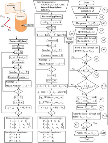
Simulation is based on the above-developed model of inspection planning and gives a measuring protocol at the output and a program code for the measurement machine ZEISS UMM 500, which, among other things, contains data on the coordinates of the measuring points and interpositions’ points. Simulation was developed using three algorithms (Fig. 8), such as:
• algorithm for measuring points distribution,
• algorithm for collision avoidance, and
• algorithm for measurement sensor path planning.
Algorithm of measuring points distribution and collision avoidance for PMP (Stojadinovic et al., Reference Stojadinovic, Majstorovic, Durakbasa and Sibalija2016a).

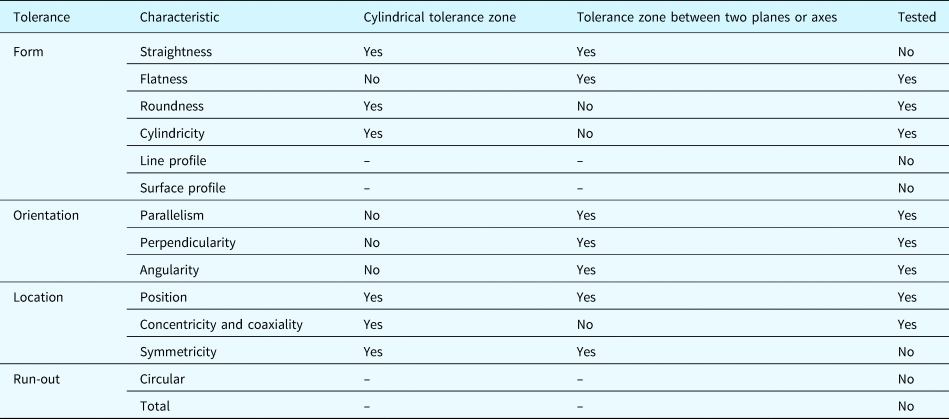
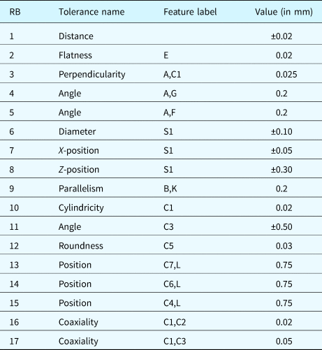
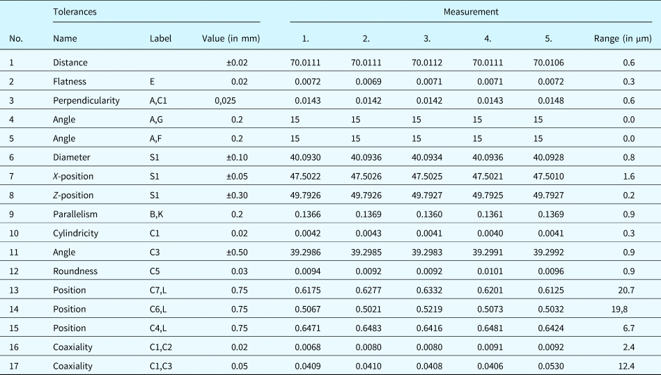
Verification of the developed model was done using specially designed and machined test PMP. A measurement part was designed to contain all geometric features included in the developed model and a considerable number of standard form tolerances (Table 2). Specified tolerance values with labels indicating the features they refer to are given in Table 3.
Standard form tolerances involved

PMP tolerances

Inspection plan
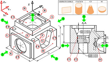
Inspection plan contains all data needed for writing the program for a measurement machine. For the test PMP according to Stojadinovic and Majstorovic (Reference Stojadinovic and Majstorovic2019), Figure 9 shows coordinate systems, labeled geometric features planned for inspection, and some of the characteristics such as the coordinate of the sphere center, position of the cylinder and cone axes, approach directions for the features, and data for measurement part leveling. Leveling consists of fixing Z-axis across plane A, then fixing X-axis across plane D. Axis Y and coordinate origin are formed by the contact at one point in the plane A.
PMP and features for inspection.

The inspection process in our experiment consists of the preparation process and the measurement process. The preparation process involves:
• measurement part setup and fixing based on performed analysis in the present paper,
• probe configuration, also using the method described in this paper,
• probe calibration just before the start of the measurement process, and
• leveling PMP.
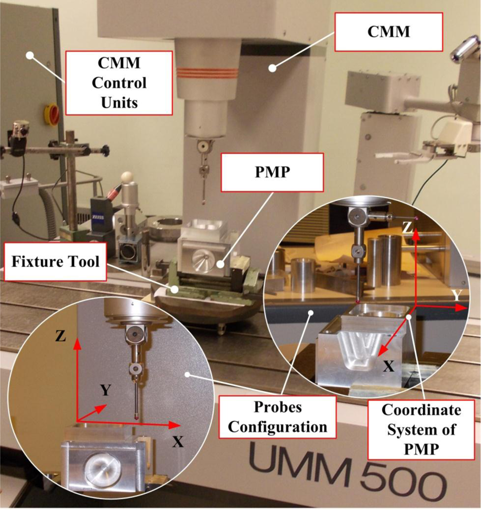
The measurement process is based on the measuring protocol obtained as the output of the simulation process and program code (steuerdatenliste ZEISS UMESS). The test PMP measuring was carried out in a single fixing and probe configuration obtained based on described methodology. Using the generated measuring protocol, a CMM was programmed. The developed model uses the underlying available software UMESS as an evaluation criterion of the measurement process. Experimental installation for measuring PMP is displayed in Figure 10.
Inspection test PMP on a CMM ZEISS UMM500.

The experiment was carried out on the measurement machine ZEISS UMM 500; however, the developed method can be applied to other CMMs by developing the corresponding postprocessors for their software systems.
Measurement results
For labeled features given in the inspection plan for the parts, Table 4 displays measurement results for the test PMP. As evident from the tables, the measurement was repeated three times, and for each type of tolerance, the range was calculated. Inspection results for the test PMP indicate that all part tolerances are within the prescribed limits. This confirms that the presented model is another successful autonomy approach to the development of CP3M for Industry 4.0.
Results of measurements using optimal probe configuration in a single test PMP setup (Stojadinovic Reference Stojadinovic2016; Stojadinovic et al., Reference Stojadinovic, Majstorovic, Durakbasa and Sibalija2016a)

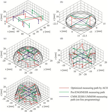
Representation of the probe path allows for its optimization applying ACO methodology based on ant colony. Applying the ACO algorithm presented in Stojadinovic et al. (Reference Stojadinovic, Majstorovic, Durakbasa and Sibalija2016b), it is finally arrived at the optimal measuring path for basic geometric features that PMPs consist of (Fig. 11). Table 5 shows the results of comparing two paths for optimal solutions of a measurement part setup and probe configuration. The first part was obtained by on-line programming of CMM, and the second, the optimal one, by applying ACO. The ratios between the values of these measuring paths for elementary metrological features are given in Table 5. As evident, the least reduction is for the feature plane 21.6% and the highest for the cylinder 40.82%. This reduction of the measuring path length is directly proportional to the measuring time reduction of the metrological feature, which is one of the contributions of presented CP3M.
Results and comparison of three obtained measuring paths for geometric features: (a) plane, (b) circle, (c) cylinder, (d) truncated cone, and (e) truncated hemisphere (Stojadinovic, Reference Stojadinovic2016).

Results of comparing two measuring paths (Stojadinovic et al., Reference Stojadinovic, Majstorovic, Durakbasa and Sibalija2016b)

Conclusion
CP2MS plays a very important role in the Industry 4.0 model for manufacturing. It is already today that manufacturers of metrology equipment, in particular of CMMs, are tending to manufacture them as a cyber-physical system, which can be used in the Industry 4.0 model. On the other hand, researchers have already presented their results from the field research of CP3M. In the coming period, rapid diffusion of these models into industrial applications should be expected, as soon as possible. For this reason, CP3M is open research space which, by integrating metrological and geometric complexity of prismatic parts, intuition, and knowledge of inspection planner, provides at the output the measuring protocol, or the program code for measurement machine control. The investigations carried out in this paper furnish the development of a new CP3M as an intelligent approach of probe configuration and setup planning for inspection of prismatic measurement parts on a CMM in order to reduce measurement time, that is, increase the measurement process productivity, and increase the planning process autonomy through minimum human involvement in the process of measurement planning and execution. Investigations are directed, in the narrow sense, to the development of global and local inspection plan for prismatic parts and obtaining optimal path for the optimal number of setups and probe configuration for each of the PMP setups on a CMM. In a broader sense, the approach combines complex analyses contained in the developed inspection planning model such as the mathematical model of prismatic parts setup, the measurement sensor accessibility analysis, the probe configuration model, the optimal PMP setup and probe configuration, and simulation of the measurement sensor optimal path obtained based on ACO. The developed prismatic parts setup model and the probe configuration model for CP3M, with the application of GA algorithm at the output, yield optimal number of PMP setups and optimal probe configuration for the cases of using probe star and probe head.
The application and benefit of the CP3M are strongly expressed in the case of geometrically complex prismatic parts inspection with a large number of tolerances and expressed geometric variance, especially in a single unit production. The CP3M is suitable for both intra-operative and final inspection in the manufacturing process.
The performed investigations represent one response to Industry 4.0 requirements such as high geometric variance (flexibility) and rapid product placement on the market (just in time) in order to reduce the total manufacturing time through reducing inspection time (productivity increase) and maintenance of ever-present requirements for inspection quality level (unification) over automation of inspection planner's activities (autonomy).
The developed CP3M remains restricted to prismatic parts, inspection cannot be applied to free-form surfaces because the inspection planning model and the optimization model were developed only for basic geometric features that prismatic parts consist of.
Financial support
The presented research was supported by the Ministry of Education, Science and Technological Development of the Republic of Serbia.
Assistant Prof. Dr. Slavenko M. Stojadinovic, Assistant Professor, Faculty of Mechanical Engineering, University of Belgrade. Professional career: 2009: Student Vice Dean, Mechanical Engineering Faculty, University of Belgrade. 2010–2016: Teaching Assistant, Mechanical Engineering Faculty, University of Belgrade. 2012–2015: Secretary of the Department for Production Engineering. 2016–present: Assistant Professor, Mechanical Engineering Faculty, University of Belgrade. Teaching experiences: 2010–today: Quality Management. Coordinate Measuring Machines. Manufacturing Technologies and Metrology. Publications: 1 book, 1 book's chapter, 6 proceeding's chapters, more than 40 scientific papers. Research Interests: His major research areas are production metrology, inspection planning on CMMs, artificial intelligence, and quality management.
Prof. Dr. Vidosav D. Majstorovic, Professor, Faculty of Mechanical Engineering, University of Belgrade. Publications/Projects: Published over 500 papers, of which more than 300 are in international journals, collections of international conferences and books issued by foreign publishers; He has done over 200 projects (domestic, international). It has 40 references to the SCI/WoS list, with 554 citations. The CIRP GA and CIRP Procedia have 11 references, etc. Membership: CIRP (International Institution for Production Research), Paris, France (since 1995); IFIP (International Federation for Information Processing), Geneva, Switzerland (since 1998); IFAC (International Federation for Automation and Control), Vienna, Austria (since 1999); IMEKO (International Confederation for Measuring), Budapest, Hungary (since 1998); etc.
Prof. Dr. Numan M. Durakbasa, Professional career: Prof. Dr. Numan M. Durakbasa is head of the Research Group “Industrial Metrology and Adaptronic Systems” and “Precision Metrology and Nanotechnology Laboratory” at the TU Wien. He is expert in the international technical Committee ISO/TC 213 “Geometrical Product Specifications”, Vice-chair of the Austrian Standard Committee “Geometrical Product Specifications”; Austrian representative in the International Measurement Confederation IMEKO. Research Interests: His major research areas are interchangeable manufacturing, precision engineering, precision metrology, geometrical product specification – GPS, micro- and nanotechnology, coordinate metrology, quality management, environmental management, industrial metrology, calibration, and standardization. Publications: 12 books, more than 500 scientific papers.