I. INTRODUCTION
Ideal end-member andradite has the formula Ca3Fe3+ 2Si3O12, schorlomite is Ca3Ti4+ 2(SiFe3+ 2)O12, and morimotoite is Ca3(Ti4+Fe2+)Si3O12. Pure end-member of schorlomite or morimotoite does not occur naturally. End-member compositions rarely occur, so how can these species be identified? Ti-rich andradite is called “melanite” if it has <1 Ti apfu, and schorlomite if it has >1 Ti apfu (Deer et al., Reference Deer, Howie and Zussman1982; Locock et al., Reference Locock, Luth, Cavell, Smith and Duke1995). Morimotoite from the type locality in Japan contains about 56 mol.% of the morimotoite end-member (Henmi et al., Reference Henmi, Kusachi and Henmi1995; Antao, Reference Antao2014). It is difficult to tell the above species apart from each other as their compositional and structural data overlap. Ti-rich andradite and their compositional boundaries were discussed (Chakhmouradian and McCammon, Reference Chakhmouradian and McCammon2005; Grew et al., Reference Grew, Locock, Mills, Galuskina, Galuskin and Hålenius2013). The type material of morimotoite from Japan has a = 12.162(3) Å and a composition {Ca2.89Mg0.09Mn2+ 0.02}[Ti4+ 1.20Fe2+ 0.56Fe3+ 0.16Zr3+ 0.06Mg0.02](Si2.32Fe3+ 0.58Al0.10)O12, but the end-member, Ca3(Ti4+Fe2+)Si3O12, could not be synthesized (Henmi et al., Reference Henmi, Kusachi and Henmi1995).
Chakhmouradian and McCammon (Reference Chakhmouradian and McCammon2005) examined the crystal structure of a schorlomite from the type locality in Magnet Cove, USA with a = 12.152(1) Å and contains 1.05 apfu Ti that are similar to the sample from Ice River, Canada with a = 12.157(3) Å and contains 1.06 apfu Ti (Peterson et al., Reference Peterson, Locock and Luth1995; Antao, Reference Antao2014). Armbruster et al. (Reference Armbruster, Birrer, Libowitzky and Beran1998) examined several Ti-rich andradites with less Ti, and their sample, AB166, has a = 12.121(1) Å and contains 0.826 apfu Ti. A synthetic sample with a considerable amount of Ti is [Ca3Fe2Si1.58Ti4+ 1.42O12], which has a large unit-cell parameter, a = 12.240(1) and the crystal structure was refined (Weber et al., Reference Weber, Virgo and Huggins1975). This chemical formula may be rewritten as Ca3[Ti4+ 1.42Fe3+ 0.58]∑2(Si1.58Fe3+ 1.42)∑3O12 with all the Ti4+ in the Y site. These examples show the Ti content and unit-cell parameters for both schorlomite and morimotoite for which complete chemical and structural data are available. How are they different from each other?
Interest in Ti-rich andradites concerns the site distribution of the various cations, as well as the distinction among andradite, schorlomite, and morimotoite. Rass (Reference Rass1997) showed that the chemical composition (oxide wt.%) and unit-cell parameters for schorlomite and morimotoite are quite similar, and questions the merit of morimotoite being different from that of schorlomite. Similar concerns are raised in this study using both chemical and structural data.
The flexibility of the garnet structure allows it to accommodate the most abundant divalent, trivalent, and tetravalent cations in the Earth's crust. The general formula for garnet is [8]
X
3
[6]
Y
2
[4]
Z
3
[4]O12, Z = 8, space group
 $Ia\overline 3 d$
, where the eight-coordinated dodecahedral X site contains Mg, Ca, Mn, or Fe2+ cations, the six-coordinated octahedral Y site contains Al, Fe3+, Ti4+, or Zr4+ cations, and the four-coordinated tetrahedral Z site contains Si, Fe3+, or Al cations, or (O4H4) (e.g., Novak and Gibbs, Reference Novak and Gibbs1971; Armbruster et al., Reference Armbruster, Birrer, Libowitzky and Beran1998). The crystal structure of garnet consists of alternating ZO4 tetrahedra and YO6 octahedra with X cations filling cavities to form XO8 dodecahedra. The eight O atoms in the XO8 dodecaheron occur at the corners of a distorted cube. Each O atom is coordinated by two X, one Y, and one Z cations in a tetrahedral configuration. The O atom is on a general position and the three cation positions are fixed. If substitution with a different size cation occurs on the Y site, for example, then the Y–O distance changes significantly, whereas the Z–O and average <X–O> distances change by minor amounts in response to that substitution (Antao, Reference Antao2013a). Similar substitutions on the other sites have similar type of effects.
Single-phase garnet is isotropic, has cubic symmetry, and the conditions did not vary during its crystallization. Recent studies show that cubic multi-phase intergrowths give rise to strain, which causes optical anisotropy in many members of the garnet group (Antao, Reference Antao2013a, Reference Antaob, Reference Antaoc; Antao and Klincker, Reference Antao and Klincker2013a, Reference Antao and Klinckerb; Antao and Round, Reference Antao and Round2014). This study uses electron-microprobe analysis (EMPA) and high-resolution powder X-ray diffraction (HRPXRD) to examine the crystal structure of an isotropic schorlomite sample from the type locality in Magnet Cove. The results for this schorlomite are compared to those for morimotoite.
II. EXPERIMENTAL
A. Sample characterization and EMPA
The black schorlomite sample (MC1) is from the central core region of Magnet Cove alkaline igneous ring complex, Hot Spring County, Arkansas, USA, where schorlomite occurs in biotite–garnet ijolite rocks (Flohr and Ross, Reference Flohr and Ross1989). Crushed thin fragments of the sample show that it is isotropic, whereas most of the other samples from this type locality in Magnet Cove are birefringent (e.g., Antao, Reference Antao2013c).
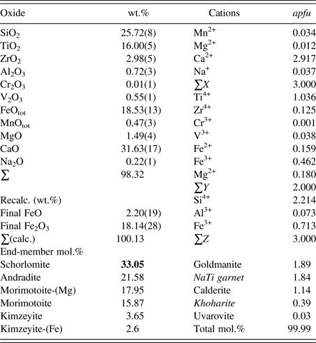
The sample was analyzed with a JEOL JXA-8200 WD-ED EMPA. The JEOL operating program on a Solaris platform was used for ZAF correction and data reduction. The wavelength-dispersive (WD) operating conditions were 15 kV, 20 nA, 5 μm beam diameter, and using various standards [almandine-pyrope (MgKα), grossular (CaKα), almandine (FeKα, AlKα, SiKα), rutile (TiKα), spessartine (MnKα), and chromite (CrKα)]. The sample is homogeneous based on optical observations and EMPA of 14 spots from different areas of the crystal. The sum of the weight percentage oxides is close to 100%, indicating an excellent analysis. The average chemical composition is given in Table I. Cation proportions (apfu) were calculated using the spreadsheet of Locock (Reference Locock2008).
EMPA results for schorlomite from the type locality in Magnet Cove (MC1) based on 12 O atoms.

The quality index is “superior”. The bold number indicates the dominant end-member.
B. Synchrotron HRPXRD
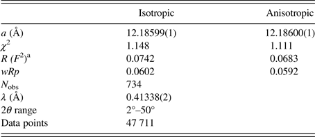
The schorlomite sample was studied by HRPXRD that was performed at beamline 11-BM, Advanced Photon Source (APS), Argonne National Laboratory (ANL). A small fragment of the sample was crushed to a fine powder using an agate mortar and pestle. The crushed sample was loaded into a Kapton capillary (0.8 mm internal diameter) and rotated during the experiment at a rate of 90 rotations per second. The data were collected at 23 °C to a maximum 2θ of about 50° with a step size of 0.001° and a step time of 0.1 s per step. The HRPXRD trace was collected with 12 silicon (111) crystal analyzers that reduce the angular range to be scanned and allow rapid acquisition of data. A silicon (NIST 640c) and alumina (NIST 676a) standard (ratio of ⅓ Si : ⅔ Al2O3) was used to calibrate the instrument and refine the monochromatic wavelength used in the experiment (Table II). Additional details of the experimental setup are given elsewhere (Antao et al., Reference Antao, Hassan, Wang, Lee and Toby2008; Lee et al., Reference Lee, Shu, Ramanathan, Preissner, Wang, Beno, Von Dreele, Ribaud, Kurtz, Antao, Jiao and Toby2008; Wang et al., Reference Wang, Toby, Lee, Ribaud, Antao, Kurtz, Ramanathan, Von Dreele and Beno2008).
HRPXRD data and Rietveld refinement statistics for schorlomite from Magnet Cove (MC1).

a R (F 2) = R-structure factor based on observed and calculated structure amplitudes = [∑(F o 2–F c 2)/∑(F o 2)]1/2.
C. Rietveld structure refinements
The HRPXRD data were analyzed by the Rietveld method (Rietveld, Reference Rietveld1969), as implemented in the GSAS program (Larson and Von Dreele, Reference Larson and Von Dreele2000), and using the EXPGUI interface (Toby, Reference Toby2001). Scattering curves for neutral atoms were used. The starting atom coordinates, cell parameter, and space group,
 $Ia\overline 3 d$
, were taken from Peterson et al. (Reference Peterson, Locock and Luth1995). The background was modeled using a Chebyschev polynomial (eight terms). The reflection-peak profiles were fitted using type-3 profile in the GSAS program. A full-matrix least-squares refinement was carried out by varying the parameters in the following sequence: a scale factor, cell parameter, atom coordinates, isotropic displacement parameters, and site occupancy factors (sofs) in terms of the dominant Ca, Ti, and Si atoms in the X, Y, and Z sites, respectively. Toward the end of the refinement, all the parameters were allowed to vary simultaneously, and the refinement proceeded to convergence. Another structural model using anisotropic displacement parameters for all the atoms was also refined. The fitted HRPXRD trace is shown in Figure 1.
HRPXRD trace for schorlomite together with the calculated (continuous line) and observed (crosses) profiles. The difference curve (I obs–I calc) is shown at the bottom. The short vertical lines indicate allowed reflection positions. (a) For the full HRPXRD trace, the intensities that are above 20° and 30° 2θ are multiplied by factors of 8 and 20, respectively. (b) Expanded scale for four peaks (400, 420, 332, and 422) showing an excellent single-phase fit.

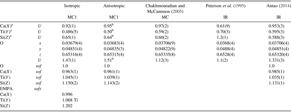
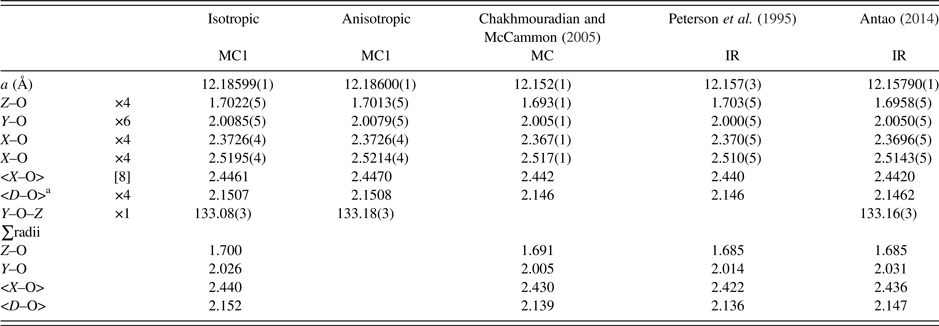
The cell parameters and the Rietveld refinement statistics are listed in Table II. Atom coordinates, isotropic displacement parameters, and sofs are given in Table IIIa. Anisotropic displacement parameters are given in Table IIIb. Bond distances and angles are given in Table IV.
Atom coordinates, displacement parameters (× 100 Å2), and sofs for schorlomite from Magnet Cove (MC1) compared to morimotoite from Ice River (IR).

a X at (0, ¼, ⅛) with Ca dominant, Y at (0, 0, 0) with Ti dominant, and Z at (⅜, 0, ¼) with Si dominant.
bEquivalent U = 1/3 trace of U ii .
Anisotropic displacement parameters (× 100 Å2) for schorlomite from Magnet Cove (MC1).

Selected distances (Å) and angles (°) for schorlomite from Magnet Cove (MC1) compared to morimotoite from Ice River (IR).

a D–O = {(Z–O) + (Y–O) + (X–O) + (X′–O)}/4. For the calculated bond distances, the following radii from Shannon (Reference Shannon1976) were used (X site: Mn2+ = 0.96, Mg = 0.89, Na = 1.18 Å; Y site: Ti4+ = 0.605, Cr3+ = 0.615, Fe2+ = 0.78, Fe3+ = 0.645, Mg = 0.72, V3+ = 0.64, Zr4+ = 0.72 Å; Z site: Si = 0.26, Al = 0.39, Fe3+ = 0.49 Å). Ca = 1.06 Å instead of 1.12 Å from Shannon (Reference Shannon1976); this gives more realistic <X–O> distances.
III. RESULTS AND DISCUSSION
The EMPA results indicate a homogeneous phase with an average composition of {Ca2.92Na0.04Mn2+ 0.03Mg0.01}Σ3[Ti1.04Fe3+ 0.46Mg0.18Fe2+ 0.16Zr4+ 0.13V3+ 0.04]Σ2(Si2.21Fe3+ 0.71Al0.07)Σ3O12, corresponding to the formula [8] X 3 [6] Y 2 [4] Z 3 [4]O12. The dominant cation in the X site is Ca2+, Y site is Ti4+, and Z site is Si4+. Schorlomite is the dominant component, but the composition contains significant amounts (>15 mol.%) of andradite, Ca3(Fe3+ 2)Si3O12, morimotoite, Ca3(Ti4+Fe2+)Si3O12, and morimotoite-(Mg), Ca3(Ti4+Mg)Si3O12 (Table I).
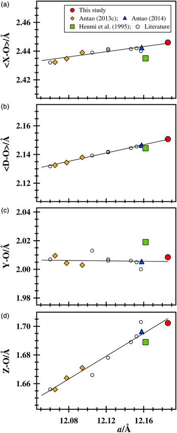
Using isotropic displacement parameters, the χ 2 and R (F 2) Rietveld refinement values are 1.148 and 0.0742, respectively, and a = 12.18599(1) (Å), which is a relatively large unit-cell parameter for a Ti-rich natural sample for which structural data are available (Table II; Figure 2). The distances and sofs are average <Ca–O> = 2.4461, Ti–O = 2.0085(5), Si–O = 1.7022(5) Å; Ca(sof) = 0.963(1), Ti(sof) = 1.045(1), and Si(sof) = 1.150(2) (Tables IIIa and IV). The sofs from the EMPA results are Ca(sof) = 0.996, Ti(sof) = 1.068, and Si(sof) = 1.202, and are similar to those obtained from the Rietveld refinement (Table IIIa). The distances calculated from the cation radii (Shannon, Reference Shannon1976) are average <Ca–O> = 2.44, Ti–O = 2.02, Si–O = 1.69 Å, which are similar to those obtained from the Rietveld refinement (Table IV).
(Color online) Structural variations for Ti-rich andradites, including schorlomite and morimotoite. The (a) average <X–O> , (b) mean <D–O> , (c) Y–O, and (d) Z–O distances vary linearly with the a unit-cell parameter. The linear lines are a guide to the eyes. Because there is only one independent O atom in the garnet structure, the scale on the x-axis is the same and the intervals on the y-axis (0.062 Å) are the same in each plot. The Z–O distance changes the most. The Fe3+ atoms replacing Si in the Z site controls the structural variations. Literature data are shown as open circles (Peterson et al., Reference Peterson, Locock and Luth1995; Armbruster et al., Reference Armbruster, Birrer, Libowitzky and Beran1998; Chakhmouradian and McCammon, Reference Chakhmouradian and McCammon2005), and that from Ice River as a solid-blue triangle (Antao, Reference Antao2014). Errors bars, if not seen, are smaller than the symbols.

A schorlomite sample from Magnet Cove with composition {Ca2.92Fe2+ 0.03Mn0.03Na0.02}Σ3[Ti1.05Fe3+ 0.53Fe2+ 0.20Mg0.16Zr0.06]Σ2(Si2.26Fe3+ 0.58Al0.16)Σ3O12, has a = 12.152(1) (Å) and average <X–O > =2.442, Y–O = 2.005, and Z–O = 1.693 Å (Chakhmouradian and McCammon, Reference Chakhmouradian and McCammon2005). The Ice River morimotoite sample with composition {Ca2.86Mg0.07Na0.04Mn2+ 0.03}Σ3[Ti1.06Fe3+ 0.46Fe2+ 0.37Mg0.07Zr0.04V0.01]Σ2(Si2.35Fe3+ 0.51Al0.14)Σ3O12, has a = 12.157(3) (Å) with average <X–O > =2.440, Y–O = 2.000, and Z–O = 1.703 Å (Peterson et al., Reference Peterson, Locock and Luth1995). The Ice River sample was re-examined and similar cell and structural parameters to those obtained by Peterson et al. (Reference Peterson, Locock and Luth1995) were obtained by Antao (Reference Antao2014) (Table IV).
The crystal structure of schorlomite can be rationalized using bond-valence sums (BVS) calculated in valence units (v.u.) (Wills and Brown, Reference Wills and Brown1999). For the bond distances given (Table IV), the BVS for the Ca atom in the X site is 2.24 v.u., so the Ca atom is a bit large for the X site. For Ti4+ in the Y site, the BVS is 3.55 v.u. and this site also contains Fe3+ and Fe2+ cations. The BVS for Si atom in the Z site is 3.38 v.u., which is reasonable because there are some Fe3+ and Al cations in this site (Table I). The BVS for the O atom is 2.0 v.u.
The unit-cell and bond distances for schorlomite and morimotoite samples from various sources are compared in Figure 2. All the samples listed in Table IV have nearly the same Ti content, but the cell parameter from this study is quite large compared to the others that have similar values (Figure 2). The Y–O distance is nearly constant and the Z–O distance changes the most. The Fe3+ atoms replacing Si in the Z site controls the structural variations. The Al content in the Z site is nearly constant for the samples from Magnet Cove and Ice River. The Y–O distance is nearly constant because of the relation: 2Fe3+ (radius = 0.645 Å) ↔ Ti4+ 1.5 + Fe2+ 0.5 (effective radius = 0.649 Å) gives rise to exchange of atoms with similar size in the Y site. The <X–O> and Y–O distances from this study are slightly larger than those observed by Peterson et al. (Reference Peterson, Locock and Luth1995), but the Z–O distances are the same. All three distances are slightly larger than those obtained by Chakhmouradian and McCammon (Reference Chakhmouradian and McCammon2005). The larger unit-cell parameter observed in the present study is related to the cations (Fe3+ and Al3+) in the Z site instead of the Zr4+ in the Y site because Y–O is constant and Z–O increases the most (Zr = 0.125 apfu; Table IV; Figure 2).
Based on radii sums and using the composition for the morimotoite sample from the type locality in Japan (Henmi et al., Reference Henmi, Kusachi and Henmi1995), bond distances were calculated and are displayed in Figure 2. These results show that chemically and structurally schorlomite from Magnet Cove cannot be distinguished from morimotoite from Ice River or Japan because they have similar parameters. Therefore, the classification of morimotoite as a valid mineral that is different from schorlomite is questionable, as was already pointed out by Rass (Reference Rass1997). However, morimotoite is presently recognized as a valid mineral by the Commission on New Minerals, Nomenclature and Classification of the International Mineralogical Association (Grew et al., Reference Grew, Locock, Mills, Galuskina, Galuskin and Hålenius2013).
ACKNOWLEDGMENTS
The Editor X. Chen and the two anonymous reviewers are thanked for their helpful comments on this manuscript. J. Michael Howard is thanked for providing a suite of schorlomite samples from Magnet Cove, Hot Spring Co., Arkansas. R. Marr is thanked for help with the EMPA data collection. The HRPXRD data were collected at the X-ray Operations and Research beamline 11-BM, Advanced Photon Source (APS), Argonne National Laboratory (ANL). Use of the APS was supported by the US Department of Energy, Office of Science, Office of Basic Energy Sciences, under Contract No. DE-AC02-06CH11357. This work was supported with a NSERC Discovery grant.