I. INTRODUCTION
Three-dimensional (3D) helical materials have stimulated worldwide enthusiasm due to their peculiar morphologies, unique properties, and interesting growth mechanisms.Reference Lau, Lu and Hui1–Reference Zhao, Huang, Zhang, Nie and Wei5 Carbon nanocoils (CNCs), as a kind of important 3D materials, have attracted much attention due to their outstanding mechanicalReference Chen, Zhang, Dikin, Ding, Ruoff, Pan and Nakayama6 and electromagneticReference Hayashida, Pan and Nakayama7, Reference Tang, Zhong, Au, Yang, Han, Lin and Du8 properties, which are expected to have wide applications, such as high-performance electromagnetic wave absorbers, field emitters, nanosprings, microsensors, etc.Reference Pan, Hayashida, Zhang and Nakayama9–Reference Pan, Zhang and Nakayama13 To realize these applications, it is necessary to control the morphology of the grown CNCs and understand their growth mechanisms. It is generally recognized that the morphology of the grown CNCs are mainly determined by structures and compositions of the used metal or alloy catalysts.Reference Zhang, Nakayama and Pan12–Reference Motojima, Itoh, Asakura and Iwanaga16 So far, CNCs have been successfully synthesized by using iron-coated indium tin oxide (ITO) catalyst,Reference Pan, Zhang and Nakayama13 Ni–P-based binary alloys catalysts,Reference Ding, Wang and Dozier17 sputtered films of Au metal or Au–Ni alloys catalysts,Reference Kuzuya, In-Hwang, Hirako, Hishikawa and Motojima18 etc. Most of the catalyst particles are observed at the tips of the coils indicating a tip growth mechanism. In addition, several proposals have been made that the growth of a CNC or a carbon microcoil (CMC) is due to the nonuniformity of the carbon extrusion speed at different parts of the catalyst particle at the coil tip.Reference Amelinckx, Zhang, Bernaerts, Zhang, Ivanov and Nagy10, Reference Pan, Zhang and Nakayama13, Reference Motojima and Chen19 Amelinckx et al.Reference Amelinckx, Zhang, Bernaerts, Zhang, Ivanov and Nagy10 proposed a model of spatial velocity hodograph to describe a formation mechanism for a catalytically grown CNC. Pan et al. developed Fe–In–Sn–O alloy catalysts for synthesizing CNCs and considered that the mechanism of CNC formation is due to that the catalyst particle at the tip of the CNC is not uniform and thus causes the difference in the extrusion velocities of carbon network between inner and outer sides of the CNC.Reference Zhang, Nakayama and Pan12, Reference Pan, Zhang and Nakayama13, Reference Okazaki, Hosokawa, Goto and Nakayama20–Reference Nakayama22 Similarly, Motojima et al. proposed two-dimensional and 3D growth models of carbon coils (usually double helical CMCs) based on the anisotropy of carbon grain deposition rate from the crystal faces of the catalyst.Reference Motojima and Chen19, Reference Motojima, Asakura, Hirata and Iwanaga23–Reference Chen, Motojima and Iwanga25 The above explanations have explored the fundamental relationship (interaction) between the growth of carbon coils and the catalyst particles at the coil tips from the viewpoints of catalytic chemistry and crystallography. However, the relation between the base of a CNC and the substrate/supporter (aggregate) at which the CNC is grown from has not yet been entirely discussed. As far as we know, no CNC or CMC has been synthesized by catalysts without the supporters. Pan et al. have reported that one or several CNCs are grown from an aggregate with a size much larger than the line diameters of the grown coils.Reference Pan, Hayashida and Nakayama26, Reference Kanada, Pan, Akita, Okazaki, Hirahara and Nakayama27 Chen et al.Reference Chen, Yang, Takeuchi, Hashishin, Iwanaga and Motojima28, Reference Chen, Takechi, Yang and Motojima29 have prepared twisted CNCs and spring-like CNCs on graphite substrate by using a Ni catalyst supported on Al2O3 powder and molecular sieve, respectively. Recently, Hanus et al.Reference Hanus, Linkson and Harris30 also have prepared twisted CNCs without substrate in a fluidized-bed reactor by using NiSO4/Al2O3 as the catalyst. From the above explanations, it can be concluded that these large supporters (aggregates, Al2O3 powder, or molecular sieve) are needed for the CNC growth. Carbon nanotubes (CNTs) grown in the similar methods, however, do not need such large supporters, they can be directly synthesized by the floating catalysts.Reference Zheng, Shi, Feng and Guo31
In this research, we have studied the role of catalyst aggregates in the growth of CNCs on different substrates, including SiO2 substrate and ITO glass substrate, and mainly focused on the relation between the base of a CNC and the catalyst aggregate at which the CNC is grown from.
II. EXPERIMENTAL
A solution of FeCl3·6H2O/SnCl2·5H2O with concentration of 0.2 mol/L was used as the catalyst precursor. The molar ratio of Fe to Sn was maintained at 3:1. Three kinds of catalysts were prepared as follows: (i) Catalyst solution with volume of 100 μl was coated on the SiO2 substrate (sizes: 10 × 10 mm2) by a dip-coating method, and dried at 40 °C for 10 min. A thick catalyst film was obtained by this method. (ii) Catalyst solution with volume of 10 μl was coated on the SiO2 substrate by a spin-coating method. Through this way, the discrete catalyst aggregates in a lower density were formed. (iii) FeCl3·6H2O solution with concentration of 0.2 mol/L and volume of 10 μl was spin-coated on the ITO glass substrate. Catalyst aggregates with different sizes were formed by selecting different rotating speeds. These three catalysts were then calcined at 700 °C for 30 min. CNCs were synthesized by a thermal chemical vapor deposition method at 700 °C for 30 min by introducing acetylene and Ar gases with flow rates of 15 and 245 sccm, respectively.
The catalyst aggregates were prepared by a spin coater (SC-1B). The catalysts and carbon deposits were observed and analyzed by a scanning electron microscope (SEM; Hitachi S-4800, Tokyo, Japan) and an atomic force microscope (AFM; Agilent PicoPlusII, Agilent, Santa Clara, CA).
III. RESULTS AND DISCUSSION
A. Growth of CNCs by Fe–Sn catalysts on the SiO2 substrate
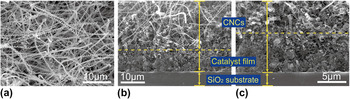
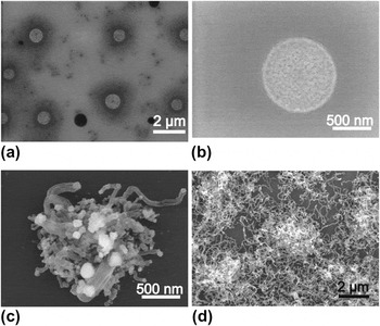
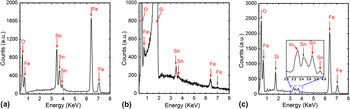
Figure 1 shows the SEM images of the CNCs grown on a SiO2 substrate coated with a Fe–Sn catalyst film. It is found that more than 95% of the deposits are CNCs with various diameters and pitches, and the CNCs grow with almost a uniform density on the whole area of the SiO2 substrate [Fig. 1(a)]. Figures 1(b) and 1(c) show the cross-sectional SEM images of the carbon deposits (upper) with a thick catalyst film (middle) grown on SiO2 substrate (bottom). It is observed that the CNCs are grown in a high yield only on the surface of the catalyst films, but no CNC has been formed in the internal, especially the bottom parts of the catalyst film. The thickness of the catalyst film is observed to be approximately 10 μm, and only a small part of the particles are served as the catalysts for the growth of CNCs. Large number of the catalysts do not contribute to the growth of CNCs, but contribute to the carbon precipitation to form an expanding layer of the mixture of catalyst carbides and carbon deposits. To improve the catalyst utilization, the thickness of the catalyst film has been reduced by decreasing the concentration of the Fe–Sn containing solution. It is found that with decrease of the catalyst thickness, the diameters, pitches, and density of the grown CNCs are all reduced. When the catalyst thickness is decreased to the nanometer scale of approximately 100 nm, the catalyst film is changed into the discrete catalyst aggregates, which is due to the low condensation of the Fe–Sn containing solution. Figure 2(a) shows the SEM image of the catalyst aggregates with a uniform distribution calcined at 700 °C for 30 min. High-resolution (HR) image of a typical catalyst aggregate is shown in Fig. 2(b). It is observed that the catalyst aggregate has a diameter of approximately 1 μm and has a porous structure on its surface. Energy dispersive x-ray spectroscopy (EDX) [Fig. 3(b)] indicates that the catalyst aggregate is mainly composed of Fe, Sn, and O (Si is mainly originated from the SiO2 substrate), and the molar ratio of Fe to Sn is approximately 3:1, which should be suitable for the CNC growth.Reference Okazaki, Hosokawa, Goto and Nakayama20, Reference Li, Pan, Qian and Liu32, Reference Li, Pan, Qian and Ma33Figure 2(c) shows the SEM image of the sample after feeding acetylene with a flow rate of 1 sccm at 700 °C for 200 s. It is found that some carbon nanofibers or germinations of CNCs have just grown from the surface of the aggregate. Catalyst particles are observed at the tip of the CNC bud, indicating a tip growth mechanism. With increase of the growth time, no CNC, but only some irregular carbon nanofibers have been synthesized on these discrete aggregates [Fig. 2(d)].
Scanning electron microscope (SEM) images of (a) top view, (b) and (c) side views for the carbon deposits grown by Fe–Sn catalyst film on a SiO2 substrate.

(a) SEM image of the discrete catalyst aggregates on a SiO2 substrate after calcination at 700 °C for 30 min. (b) High-resolution (HR) SEM image of a single calcined catalyst aggregate. SEM images of a catalyst aggregate formed by feeding acetylene at 700 °C for (c) 200 s and (d) 30 min.

Energy dispersive x-ray spectroscopy spectra of calcined (a) thick Fe–Sn catalyst film on SiO2 substrate, (b) single Fe–Sn catalyst aggregate on SiO2 substrate, and (c) single catalyst aggregate on indium tin oxide (ITO) glass substrate.

According to the above experiments, CNCs in high yield can be grown from the thick Fe–Sn catalyst film on a SiO2 substrate, however, only irregular (not coiled) carbon structures are grown from the Fe–Sn catalyst aggregates on the same substrate. It has been reported that both Fe–Sn binary alloys and Fe–In–Sn ternary alloys are effective catalysts for synthesizing CNCs, where Fe, Sn, or In in catalysts play different roles in the growth of CNCs.Reference Pan, Zhang and Nakayama13, Reference Li, Pan, Qian and Liu32 It has been found that Fe is crucial in the formation of a carbon tubule, while neither CNCs nor carbon fibers is grown only with In2O3 and SnO2.Reference Okazaki, Hosokawa, Goto and Nakayama20–Reference Nakayama22 In addition, Sn is required to grow CNCs, and the composition of Sn in catalysts should be small to grow CNCs in high yield. In this experiment, EDX spectra analysis shows that the molar ratio of Fe to Sn in the catalyst aggregate is approximately 3:1 [Fig. 3(b)], which is similar to those of the thick Fe–Sn catalyst film [Fig. 3(a)] and the previous reports.Reference Okazaki, Hosokawa, Goto and Nakayama20, Reference Li, Pan, Qian and Liu32 Therefore, it seems that the calcined Fe–Sn catalyst aggregate on SiO2 substrate would be suitable for the CNC growth. Looking from another perspective, the main differences between the thick Fe–Sn catalyst film and the discrete Fe–Sn aggregates are their sizes and thicknesses, which lead to the growth of different carbon deposits. The thick Fe–Sn catalyst film looks like a compact “soil” layer, playing a role of fixing the base of the grown carbon fibers, from which a large number of CNCs can grow. However, the thin Fe–Sn aggregate on the flat SiO2 substrate cannot serve as such a compact “soil” layer to fix the base of a grown carbon fiber firmly.
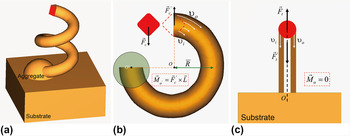
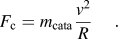
It is accepted from the viewpoint of mechanics that the spiral motion of a CNC should generate a torsional moment on its base which attaches to an aggregate. Based on the experimental results, the growth of CNC is analyzed from the viewpoint of mechanics and its well-established model, as shown in Fig. 4. Figure 4(a) shows the 3D model of a CNC, which is grown from the aggregate on a substrate. The motion trail of the catalyst particle on tip of the CNC is certainly spiral, and this motion can be decomposed into two: uniform circular motion and uniform linear motion (ULM) which is vertical to the circumferential surface. In this report, ULM is not taking into consideration since it has no relation with a moment of force. The gravity of the catalyst and CNC is also neglected for simplicity. Figure 4(b) shows the mechanical analysis of the catalyst particle and the grown CNC. R, ν o, and v i are the radius of the CNC and the velocities of carbon extrusion from the outer and inner sides of the catalyst particle, respectively. The nonuniformity of carbon extrusion (ν o > v i) produces a centripetal force F c to the catalyst to maintain its circular motion, meanwhile, CNC itself gets a reaction force F′ c (F′ c = −F c) from the catalyst particle. Then a torsional moment M o′ is generated at the CNC tip toward its fixed base O′, which deviates from the center of the circular motion O for L, where  . The magnitude of generated M o′ is estimated as follows:

(a) Three-dimensional growth model of carbon nanocoil (CNC), the mechanical analysis of the (b) CNC and (c) the carbon nanotubes with catalyst particles on their tips.

where m cata and ν are the mass and velocity of the catalyst particle on tip of the CNC, respectively. Substituting Eq. (2) into Eq. (1), we get
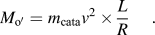
First, assume  . Then

The catalyst is mainly composed of iron carbide.Reference Nishimura, Pan and Nakayama14 Therefore, assuming the catalyst density  .Reference Zhang, Zhang, Fang, Li, Li and Sun34 In addition, the catalyst particle is simplified to a cube structure whose side length is equal to the line diameter of the CNC. For CNC, assume the line diameter (d), coil diameter (D), and coil pitch (S) of CNC 200, 500, and 500 nm, respectively. The length (H) of CNC can reach up to 100 μm in period (t) of 30 min.
According to the above assumptions,

The total length of CNC (motion trial of the catalyst) in period of t can be described as follows:

Then

Substituting Eqs. (5) and (7) into Eq. (4), we get

This torsional moment should be balanced by the compact aggregate that fixes the CNC base to maintain the spiral growth of the CNC. For the CNT shown in Fig. 4(c), the direction of reaction force from the catalyst particle passes through the center of the CNT base O, i.e.,  , therefore the base fixing is not needed for its growth.
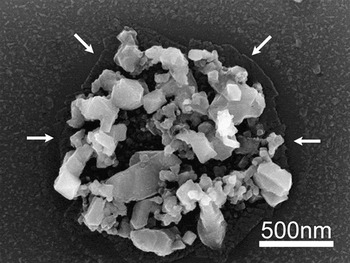
It is considered that there exist two interaction forces between an aggregate and the substrate during the CNC growth, one is the van der Waals force and the other is the static friction force that is produced by the spiral growth of CNCs. The interaction between aggregate and substrate would become weak with decrease of the aggregate sizes. To demonstrate the weak interaction between catalyst aggregate and flat SiO2 substrate, the morphology changes of catalyst aggregates by feeding acetylene for short time ranging from 0 to 200 s have been investigated. Figure 5 shows the SEM image of a catalyst aggregate on a SiO2 substrate after calcination at 700 °C and then by feeding acetylene at 700 °C for 100 s. Differing from the catalyst aggregate only after the calcination process [Fig. 2(b)], the aggregate has changed into some isolated particles with different sizes and shapes. The formation of these particles is considered to be due to the self-arranged migration and fusion of the reduced metallic nanoparticles. In addition, the bottom of the aggregate is found to have partially separated from the surroundings (indicated by white arrows), and probably detached from the surfaces of SiO2 substrate to some extent, indicating a weak interaction between the aggregate and the substrate. When the acetylene feeding time reaches 200 s, the large particles begin to be jacked up and some carbon fibers have been grown [Fig. 2c)]. Therefore, less catalyst particles exist at the base and a loose aggregate is formed. The loose aggregate with isolated particles on the flat substrate cannot provide a strong interaction between the aggregate and the base of the grown carbon fiber and therefore cannot balance the torsional moment of the CNC during its spiral growth. In other words, firmly fixing the base of the grown carbon fiber is essential to allow its spiral growth into CNC. To prove this fact, a kind of substrate that can improve the interaction between the aggregate and the grown carbon fiber base is needed.
SEM image of a calcined catalyst aggregate on a SiO2 substrate by feeding acetylene at 700 °C for 100 s.

B. Growth of CNCs by discrete Fe–Sn catalyst aggregates on the ITO glass substrate
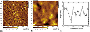
Instead of the flat SiO2 substrate, ITO glass has been selected as the substrate. It is known that ITO glass is easily softening and deforming at the temperature higher than 550 °C. Therefore, ITO glass substrate maybe a suitable candidate that could restrict the expansion of the catalyst particles, leading to the formation of a compact aggregate. The compact aggregate would firmly fix the base of the grown carbon fiber and make it possible to fabricate CNCs in a lower density. Figure 6 shows the AFM images of a typical ITO glass substrate. It is observed that the surface of the ITO glass is mainly composed of the continuous flake structures, among which some nanosized holes can be found and their average depth is approximately 5 nm [Figs. 6(b) and 6(c)].
(a) Low and (b) high magnification atomic force microscope (AFM) images of ITO glass substrate. (c) The cross-section height along the line drawn in Fig. 6(b).

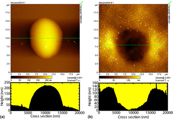
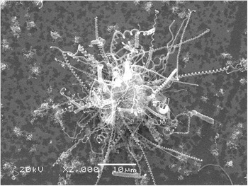
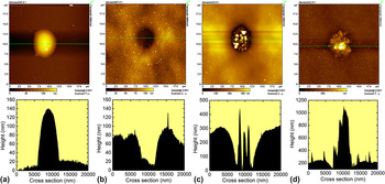
Figure 7 shows the AFM images of a typical large catalyst aggregate on the ITO glass substrate prepared by a spin-coating method with a rotating speed of 2000 rpm (a) after drying at 100 °C and (b) after calcination at 700 °C for 30 min. Differing from the catalyst aggregates prepared on SiO2 substrate, the catalyst aggregate on the ITO glass substrate is changing from the bulgy hemisphere structure (after drying) to the cylindrical hole structure (after calcination). The hole structure formation process can be explained as follows: After FeCl3 solution is spin-coated on the ITO glass substrate and dried at 100 °C, FeCl3 aggregates are formed on the ITO glass surface [Fig. 7(a)]. With increase of the temperature, FeCl3 aggregate begins hydrolysis, generating Fe(OH)3 and HCl, then HCl and InO react with InCl2. When the temperature rises more than 600 °C, InCl2 volatilizes in gaseous form, and Fe(OH)3 has completely decomposed into Fe2O3. A great loss of InO in ITO film finally leads to the hole structure formation on the ITO glass surface [Fig. 7(b)]. This kind of holes has an average diameter of 10 μm and a depth of approximately 150 nm. EDX spectra analysis demonstrates that the bottom part of the hole is composed of Fe, Sn, In, and O (Si is mainly originated from the glass substrate) [Fig. 3(c)], indicating that Fe–Sn(In)–O catalysts are formed after calcination and mainly distribute in the bottom of the hole. The other difference between Figs. 7(a) and 7(b) is that some particles (bright spots around the hole) with uniform distribution have protruded out on the substrate surface after calcination [Fig. 7(b)]. These particles are originated from the aggregation and the deformation of ITO film at higher temperature (>600 °C). Figure 8 shows the SEM image of the CNCs grown from this kind of catalyst aggregate. It is found that CNCs, with wide distributions of coil diameter and pitch ranging from several tens to several hundreds of nanometers, grow radiately from the catalyst aggregate, which is similar to those described by Pan et al.Reference Pan, Hayashida and Nakayama26 It is considered that this kind of microsized holes formed on the surface of ITO glass substrate would gather catalysts easily. In the process of carbonization and carbon precipitation, the expansion of the catalyst particles in a microsized hole is restricted by the surrounding wall of the hole, leading to the formation of a compact aggregate that could firmly fix the base of the grown CNC.
AFM topographies and their corresponding cross sections of a large catalyst aggregate on the ITO substrate (a) after drying at 100 °C for 30 min and (b) after calcination at 700 °C for 30 min. The bright spots in Fig. 7(b) are formed due to the aggregation and the deformation of ITO film at higher temperature (>600 °C).

SEM image of the CNCs grown from a large catalyst aggregate on the ITO glass substrate.

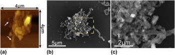
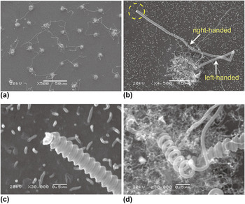
The relatively small catalyst aggregates on the ITO glass substrate are prepared by a spin-coating method with a rotating speed of 3000 rpm. Figures 9(a) and 9(b) show the AFM images of a small single catalyst aggregate after drying at 100 °C and calcination at 700 °C, respectively. Similar to Fig. 7, the small aggregate is also changing from a hemisphere structure [Fig. 9(a)] to a cylindrical hole structure [Fig. 9(b)]. It is observed in Fig. 9(b) that the catalyst aggregate has a plane size of 5 μm and a depth of only 80 nm, which are smaller than that of large aggregate [Fig. 7(b)]. Figure 9(c) shows the AFM image of a catalyst aggregate by feeding acetylene for 2 s. It is found that a few large particles with a height of approximately 300 nm have protruded out from the bottom of the hole, meanwhile some smaller particles are formed. When the feeding time reaches 50 s, the catalyst particles begin to absorb carbon atoms, leading to their volume expansion [Fig. 9(d)]. A careful observation in Fig. 9(d) shows that some smaller particles distribute around the aggregate and the height is nearly 1000 nm, which indicates that carbon fiber bud has protruded out from the center of the aggregate. Figure 10(a) shows the AFM image of a single catalyst aggregate by feeding acetylene for 200 s. It can be seen that small particles have expanded into the relatively large particles due to the continuous carburizing; meanwhile several short carbon fibers have grown from the aggregate (indicated by white arrows). After feeding acetylene for a time of 1000 s, a short CNC has been grown out as shown in Fig. 10(b). In addition, some irregular short carbon fibers/tubules, combined with some amorphous carbon block, are formed on those small catalyst particles [Fig. 10(c)]. These amorphous carbon and irregular carbon fibers may form a compact aggregate where the CNC can be grown. After feeding acetylene for 30 min, CNCs have successfully grown from the catalyst aggregate on the ITO glass substrate (Fig. 11). Figure 11(a) shows the SEM image of the CNCs and catalyst aggregates distribution on the ITO substrate. A careful observation reveals that no more than three CNCs have precipitated out from each aggregate, sometimes only a single CNC can grow. Figure 11(b) shows the SEM image of two CNCs grown from a catalyst aggregate. The catalyst particle is observed at the tip of the carbon coil, indicating a tip growth mechanism [Fig. 11(c)]. Figure 11(d) shows the base of the carbon coil, which is connected with the aggregate. It is also found in Fig. 11(b) that the grown CNC is composed of two parts, one is the left-handed CNC and the other is the right-handed CNC, which can be further confirmed by HR images of Figs. 11(c) and 11(d).
AFM topographies and their corresponding cross sections of a small single catalyst aggregate on the ITO substrate (a) after drying at 100 °C, (b) after calcination at 700 °C, and in the case of feeding acetylene for (c) 2 and (d) 50 s.

(a) AFM image of single catalyst aggregate on the ITO substrate by feeding acetylene for 200 s, (b) SEM image of single catalyst aggregate by feeding acetylene for 1000 s, and (c) the enlarged SEM image of the aggregate marked by a dashed circle in Fig. 10(b).

SEM images of the CNCs grown from the small catalyst aggregates on ITO glass substrate. (a) Low magnification image of the product. (b) a typical single CNC grown from the small catalyst aggregate. HR images of the (c) CNC tip and (d) CNC base.

IV. CONCLUSIONS
We have studied the role of catalyst aggregates in the growth of CNCs on different substrates and mainly focused on the relation between the base of a CNC and the catalyst aggregate where the CNC is grown from. It is found that a compact aggregate is formed in the microporous structure and can fix the base of a grown carbon nanofibers. So, CNCs can be grown from the discrete aggregates on a substrate with a porous surface. However, only some irregular carbon nanofibers are grown from the discrete aggregates on a flat substrate. It is considered that a loose aggregate is formed on the flat substrate and cannot fix the base of a carbon fiber grown there. Therefore, firmly fixing the base of a CNC is proven to be a necessary condition for its spiral growth.
ACKNOWLEGMENTS
This work was supported by the National Natural Science Foundation of China (No. 51072027, No. 60977055) and the Project for Scientific Researches of 2009 in Universities from the Education Department of Liaoning Province (No. 2009S016).