Introduction
Based on a radio frequency detection principle, radio frequency identification (RFID) represents an advanced spectacular technology in comparison to the barcode techniques, making possible the simultaneous identification of various objects distant by several meters and without direct sight considered as blind identification. This system consists of an antenna and a microchip; these smart labels “tags” remain too expensive for certain traceability applications [Reference Marindra, Pongpaibool, Wallada and Siwamogsatham1]. The chipless RFID innovation thus makes it possible to combine affordable identification with higher performance than that of the barcode [Reference Lazaro, Ramos, Girbau and Villarino2–Reference Necibi, Beldi and Gharsallah5]. Chipless RFID studies the critical points to be improved to outreach the technological obstacles for the development of this device.
The system is composed of two main parts: the readers and the tags [Reference Mekki, Necibi, Boussetta and Gharsallah6, Reference Athauda and Karmakar7]. The interrogating input signals of chipless RFID tags are modulated to provide distinguishable signatures. Each time the interrogating signals are sent to the reader, the tags reply to the reader with signatures generated only by encoding. Furthermore, tags can be detected even at long distance and are more flexible in positioning with respect to the readers of the RFID system [Reference Khaliel, Awamry, Megahed and Kaiser8]. The tag can be recognized as a radar target with a particular electromagnetic signature dedicated for encoding/encryption. Tags can be divided into two main types [Reference Preradovic and Karmakar9]: the spectral-signature-based and the backscattering-based tags. The backscattering-based tag which uses radar cross-section (RCS) has a miniature size, easy readability, and deployment without the necessity of receiving and transmitting antennas.
In the literature, many papers focus on the use of chipless tags to develop high-performance RFID tags [Reference Barbot and Perret10–Reference Athauda and Karmakar21]. Relating to the used resonator, several topologies were suggested for the chipless tags. Such topologies include circular loops [Reference Athauda and Karmakar21, Reference Khaliel, El-Awamry, Fawky and Kaiser22], square loops [Reference Costa, Genovesi and Monorchio23, Reference Huang and Su24], U-shape [Reference Svanda, Polivka, Havlicek and Machac25, Reference Havlicek, Svanda, Polivka, Machac and Kracek26], C-shaped [Reference Rance, Siragusa, Auger and Perret27, Reference Antayhua, Rambo and Sousa28], octagonal [Reference Betancourt, Haase, Hübler and Ellinger29], and microstrip-line [Reference Zhang, Gao, He and Tong20, Reference Paredes, Herrojo, Escude, Ramon and Martín30, Reference Herrojo, Paredes, Bonache and Martín31]. Major parameters such as size, bit encoding capacity, bandwidth, bits states/resonators, and reading range are considered to enhance the performance of these RFID tags.
According to their encoding method, chipless RFID tags can be classified into two main classes: frequency-signature-based chipless RFID and time-domain reflectometry (TDR)-based chipless RFID. Tags that are based on the frequency-domain (FD) have higher data capacity in comparison with other encoding techniques [Reference Costa, Genovesi and Monorchio23, Reference Rmili, Oueslati, Ladhar and Sheikh32]. The main idea of the frequency encoding technique is to control the presence or absence of a resonance at particular frequencies. The presence of given resonance frequencies is identified by notches or nulls in the detected or received tag responses. Otherwise speaking, we attribute one (bit = 1) when a null exists, and we attribute zero (bit = 0) when it is absent. Each resonance is related to a physical scatterer, and the capacity of encoding is then associated with the number of resonators that exist in the tag and in the corresponding frequency band [Reference Rance, Siragusa, Auger and Perret27]. As a result, the number of possible combinations can increase exponentially by simply increasing the number of bits. In TDR-based chipless RFID, the transmission delay lines generate many different codes, and bits are recognized with their time delay [Reference Herrojo, Moras, Paredes, Nunez, Mata, Ramon and Martin33]. To detect bits, a delay between the bits is required and it can be achieved by increasing the transmission lines length or decreasing the pulse width of the involved signals [Reference Ashraf, Alshoudokhi, Behairy, Alshareef, Alshebeili, Issa and Fathallah34]. When we increase the length of transmission lines, a larger size of RFID tags results, while the spectral bandwidth is increased by the shorter pulse width. However, with comparison to FD tags, the process of calibration of tags based on time-domain encoding is simpler [Reference Shao, Amin, Chen, Liu and Zheng35].
In chipless RFID systems, the RFID reader is imperative. The RFID reader is particularly necessary for reading chipless RFID tags at large distances.
Ultra-wideband (UWB) wireless communication technologies have been drawing considerable attention amongst researchers due to the advantages such as small size, high data rate, low power consumption, low structural complexity, and low fabrication cost. Different types of structures have been investigated, such as dipole antennas [Reference Xu, Li, Wei and Yang36] and monopole antennas [Reference Almoteriy, Sobhy and Batchelor37–Reference Bai, Zhuang and Zeng46].
Circular monopole antennas have shown much wider bandwidth than the other shapes with omnidirectional radiation characteristics and a simple structure, therefore these were used in the present work. The UWB monopole antenna consists of a radiating patch and ground plane on the same side of a dielectric substrate.
From the work announced in the literature [Reference Kalansuriya and Karmakar47, Reference Kalansuriya and Karmakar48], the utilization of UWB-IR-based interrogation for frequency spectra-based chipless RFID tag did not acquire a lot of consideration.
In [Reference Kalansuriya and Karmakar47], the analyses of a multipatch-based, chipless RFID tag backscatter that is read using a UWB-IR-based reader are presented.
In [Reference Kalansuriya and Karmakar48], UWB pulsed interrogation of a chipless RFID based on a spiral resonator is considered where a meandering transmission line is utilized to isolate and demonstrate that the resonance information of the spirals is contained in the backscatter antenna mode.
In both [Reference Kalansuriya and Karmakar47, Reference Kalansuriya and Karmakar48], the methods proposed do not require a calibration tag to help the detection process and rely solely on the backscattered signal to estimate the tag's resonance information.
Nonetheless, the methods are not validated utilizing experimental results and depend just on electromagnetic simulations.
In the present work, UWB-IR is used to analyze the backscatter in both time-domain and FD in chipless RFID systems [Reference Kalansuriya and Karmakar47, Reference Karmakar49]. A new detection approach based on a chipless RFID tag was established, and it consists of patch antennas array, using UWB impulse-based interrogation as in [Reference Kalansuriya and Karmakar47, Reference Karmakar49]. The proposed system constitutes the backscattered signals and analyze their spectral content, where the structural and the antenna modes are identified. The analysis shows that the structural mode backscatter does not contain information about the tag, whereas the antenna mode backscatter contains the information carrying the signal. The obtained measurement results by the experiments in an anechoic chamber environment validate the simulation results.
The present research paper consists of several sections shown as follows: section “System model of the proposed chipless RFID tag” describes the model of the chipless RFID system. Section “Electromagnetic simulation of chipless RFID system” shows the electromagnetic simulation results of the chipless RFID system and RFID reader. Section “System validation using CST microwave studio” presents the system validation using CST Microwave Studio and analysis of the chipless tag backscatter. In section “Experimental validation of chipless RFID system”, we will discuss the measurement results in order to validate experimentally the performance of the chipless RFID tag. Finally, the last section “Conclusion” will be dedicated to the conclusion.
System model of the proposed chipless RFID tag
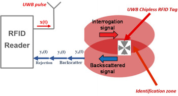
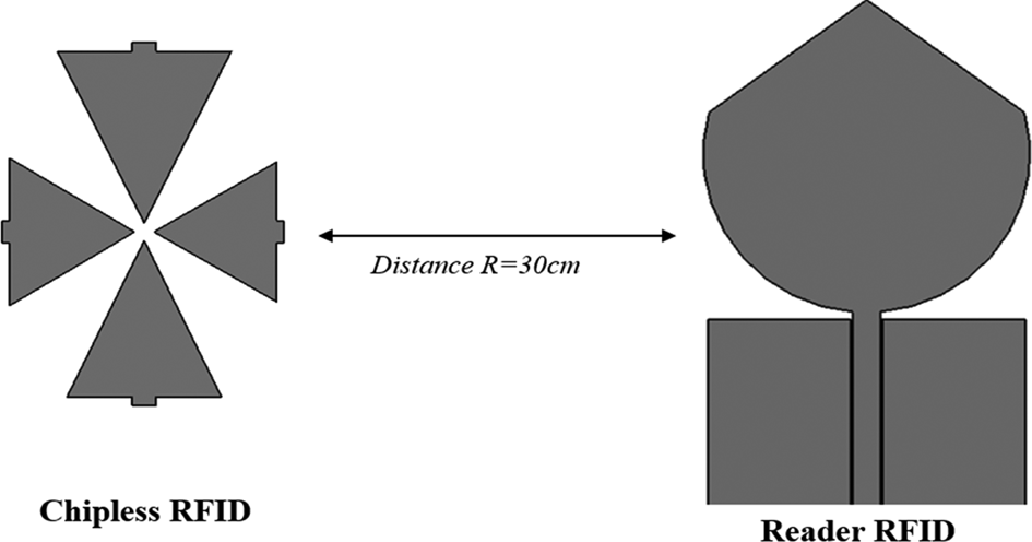
The proposed model consists of an RFID reader and a multi-resonator chipless RFID tag. The system's principle of operation is shown in Fig. 1. The RFID reader consists of one single antenna for both transmission and reception. This reader will send an interrogational signal with magnitude and phase data to the chipless tag.
Operational diagram of the chipless RFID tag and reader system.
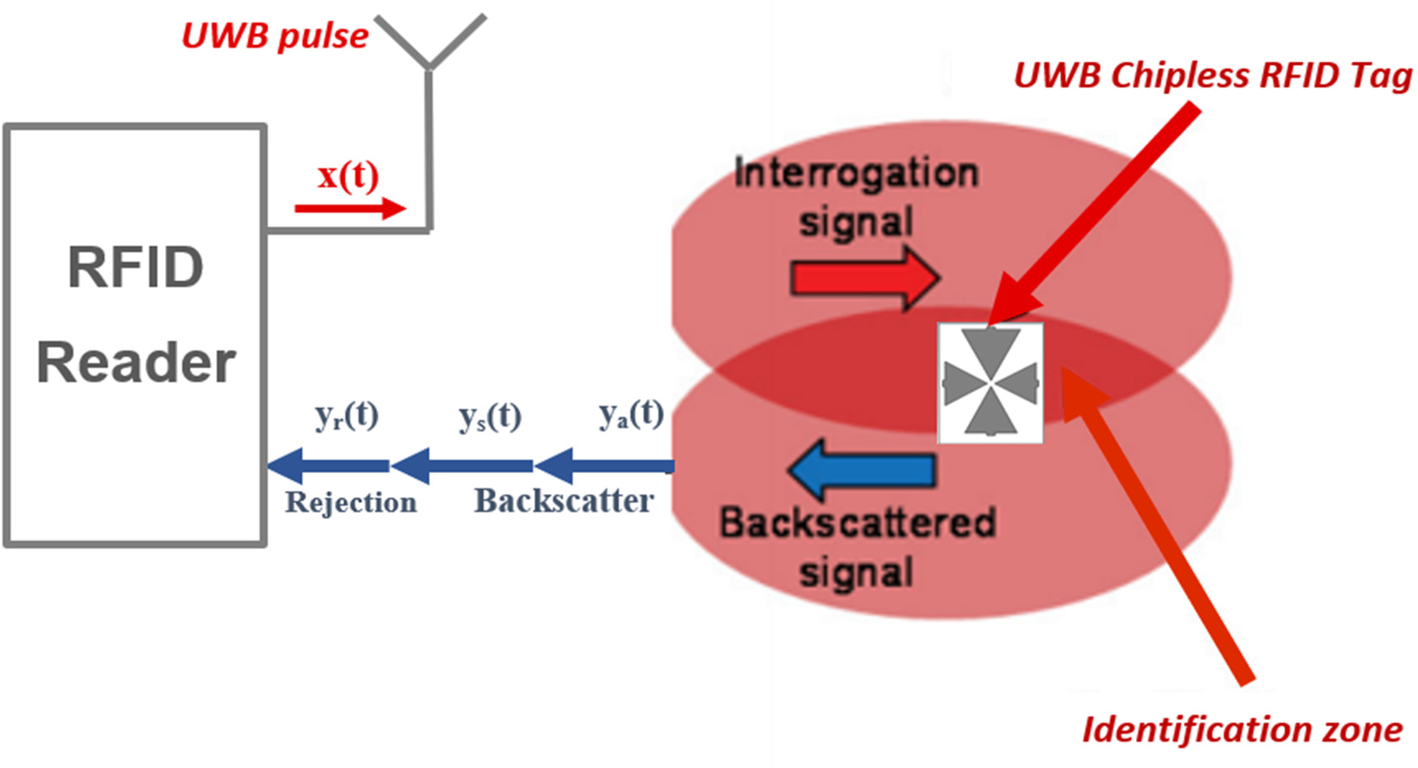
Then, the chipless tag with a multi-resonator structure encrypt the interrogation signal into frequency spectra in terms of magnitude and phase and then resend the signal back to the reader [Reference Jalil, Rahim, Samsuri and Dewan50]. When the chipless RFID tag is impinged by a vertically polarized EM wave from the transmitter antenna, a unique frequency signature was assigned, and the receiver antenna receives the encoded signal. The RFID reader device records and extracts this unique frequency signature, and so the chipless RFID tag can be recognized.
The process of backscattering was explained in details, and the main components of the signal were introduced.
The reader antenna transmits the interrogation signal x(t) and is then ready to receive any backscatter from the tag. The largest and first received component yr(t) can be considered as the rejection of the transmit pulse x(t) because of the return loss profile of the involved antenna. The transients of yr(t) gradually decrease to zero.
The total signal y(t) at the RFID reader can be shown as follows,

where ys(t) relates to the shape of the structure of the tag and it is irrespective of the resonant properties of the tag patch antennas and the structural mode of the backscatter. The component ya(t) is the weakest and the last component to be received, and it contains the relevant information from the tag [Reference Karmakar49, Reference Balanis51].
Electromagnetic simulation of chipless RFID system
The antenna design phase, using suitable software, is an essential step in order to save time and optimize structures with the desired parameters.
For the above reason, an adequate electromagnetic simulation tool must be identified and used. There are several available tools among which we used three: Femlab from Comsol, HFSS from Ansoft, and Microwave Studio from CST. We have chosen electromagnetic simulation with CST Microwave Studio because it uses a mesh method with finite integrals, the simulation of the planar patch antenna lasted less than 5 min. The simulator appears, for the case of printed antennas with a simple form, to have higher precision levels for calculations and time-solving speed.
Design of UWB monopole antenna
UWB monopole antennas can be used both as RFID reader antenna or a tag antenna [Reference Zhang, Gao, He and Tong20, Reference Prabavathi, Rani and Meena52]. They also operate in a wide frequency band.
Furthermore, this antenna type is fully printable and it seems suitable to be used as a chipless RFID tag antenna, because UWB antennas do not need an impedance-matching circuit or balun to operate successfully.
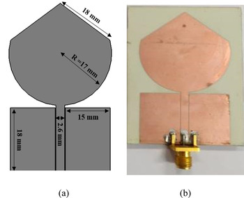
Circular UWB monopole antennas have a simple layout and exhibit a very large bandwidth. The proposed antenna consists of a circular disc that has a radius of 17 mm with two-sided corner truncation, and a finite coplanar ground plane [Reference Almoteriy, Sobhy and Batchelor37]. The design and fabrication of the antenna is performed with a Rogers RO4350B substrate, as shown in Fig. 2.
UWB monopole antenna, (a) simulated structure, (b) manufactured structure.

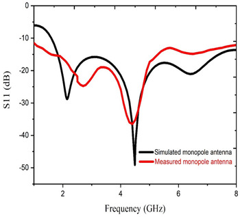
Figure 3 clearly shows the reflectance profile of the simulated and measured monopole antenna. It is performed as expected and it has a reflection coefficient of less than −10 dB from 2 to 8 GHz.
Simulated and measured reflection coefficient of the monopole antenna.

Chipless RFID tag RCS
In contrary to the wideband antennas mentioned above, the triangular patch antennas used in the tag operate in a narrow band. This resonant behavior is beneficial to design chipless RFID tags based on the magnitude of the RCS.
The RCS of a tag represents the encoding frequency signature of the tag-ID data. A microstrip patch antenna introduced in [Reference Karmakar49] was used to produce an RCS frequency signature.
To design RCS-based chipless RFID tags, different resonating elements are utilized. In [Reference Islam, Yap and Karmakar53], a triangular chipless RFID tag was introduced. The tag consists of a patch with many triangular resonators. The procedures of the design are well explained in [Reference Ahsan, Guo, Gouzouasis, Kallos and Kosmas54].
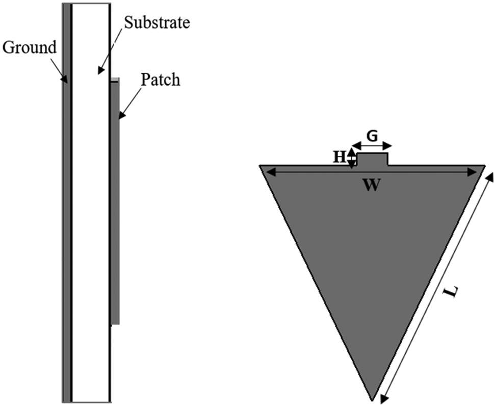
The substrate material used in the design of the triangular patch antennas is 0.76 mm-thick Rogers RO4350B (Fig. 4).
Triangular patch antenna with dimensions: L = 18, W = 16, G = 2, H = 1 (all dimensions in mm).

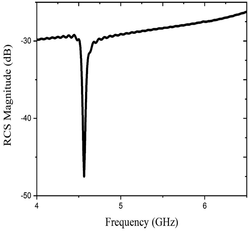
The magnitude-frequency response is shown in Fig. 5.
RCS magnitude versus frequency response of patch resonator.

On a given tag one or more patches can be loaded, and one or more of these patches can be shorted and the corresponding frequencies are thus nulled, and a data bit 0 or 1 can be encoded according to the presence or absence of a peak in the spectrum.
Design and simulation of a 4-bit patch
In the case of a multi-patch tag, an array of narrow-band patch antennas can perform different functions as the reception of the signal, the encoding of the data, and the transmission of the backscattered signals. It consists of patch antennas that have different resonant frequencies.
Every single patch antenna produces backscatter uniquely at its corresponding resonant frequency. As a result, a unique frequency signature is produced in the total backscattered signal. In such a kind of tag, the RCS serves as the frequency signature encoding the tag-ID data.
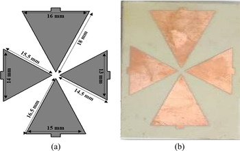
In this article, the type of multi-patch tag design is studied. The first tag is composed of four triangular patch antennas, as Fig. 6 shows.
Patch tag loaded with resonators which return the ID “1111”, (a) simulated structure, (b) manufactured structure.

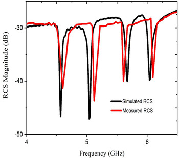
Four different lengths Li (i = 1, 2, 3, 4) patch antenna resonators are loaded on the tag. The simulation results are shown in Fig. 7, where the peaks can be clearly detected and easily distinguished.
Simulated and measured RCS magnitude versus frequency.

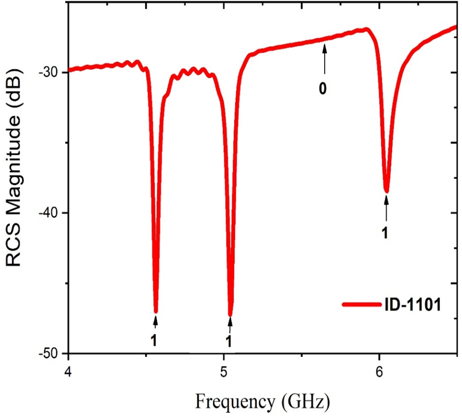
The basis of encoding used in this work is simple: in spectrum, each resonant frequency has both a peak and dip, the dip is selected to encode a high bit value “1”. When one dip is not measured, the corresponding bit is low, “0”. A tag with four resonators was presented in Fig. 6, and four dips in the magnitude response are visible in Fig. 7, thus corresponding to an ID of “1111”. In Fig. 8, a tag with only three resonators is presented, and in Fig. 9, it can be seen that the third peak has disappeared, yielding a tag with ID “1101”.
Patch tag with ID “1101” loaded with resonators.

RCS magnitude versus frequency simulation of tag.

System validation using CST microwave studio
Four-patch chipless tag and reader system
CST Microwave Studio was used to simulate the proposed chipless RFID system. Figure 10 shows the simulation setup. The RFID reader consists of one single antenna which plays the role of a transmitter and a receiver of electromagnetic signals at the same time.
Four-patch chipless RFID tag-reader system.

The circular monopole antenna plays the role of the transmit/receive antenna at the reader, where the tag and reader were placed facing one another and at a distance of 30 cm.
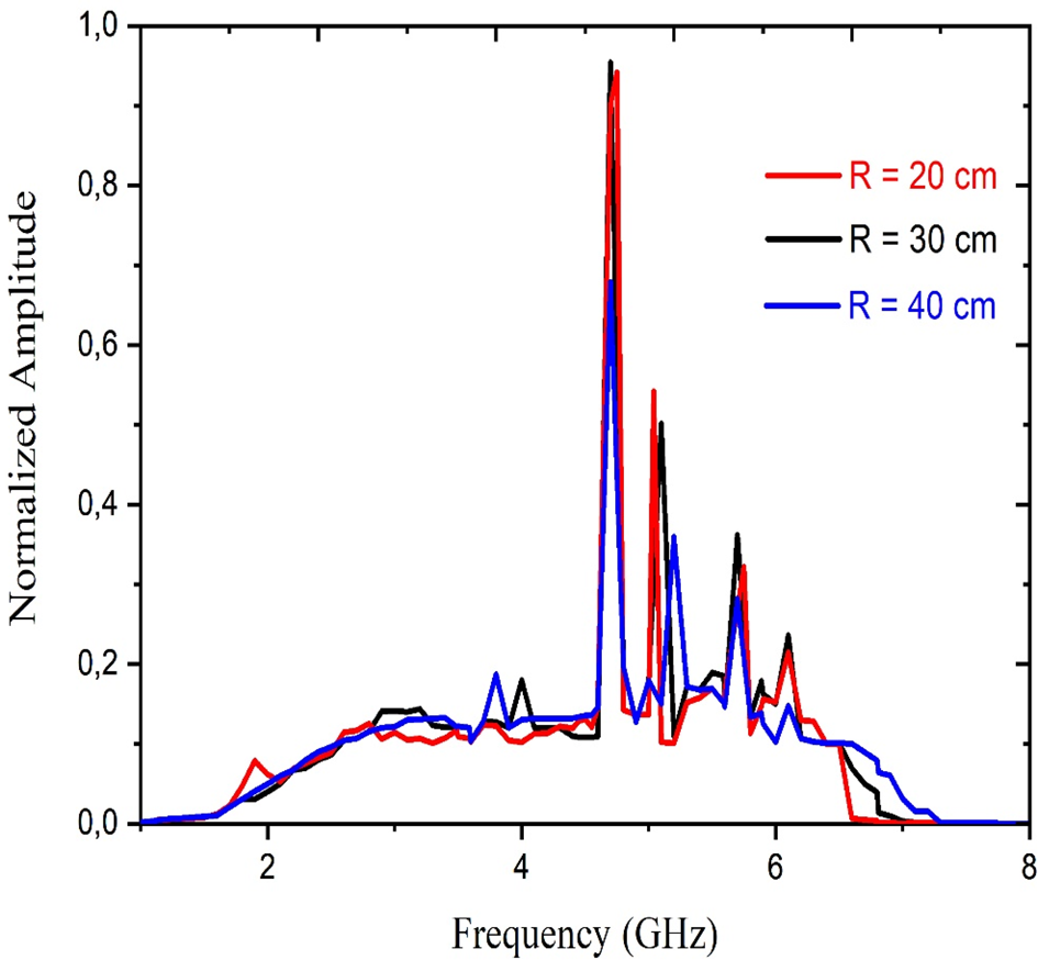
The performance of the chipless RFID system at different distances is shown in Fig. 11. A tag having resonant patch antennas at frequencies f 1, f 2, f 3, and f 4 was positioned at R = 20, 30, and 40 cm away from the reader antenna. For the different distances, the amplitude spectrum of the antenna mode backscatter is shown in the figure where the amplitudes are normalized with regard to the maximum amplitude recorded with R = 30 cm. It is clearly observed that when the distance decreases (R = 20 cm), the results of the four amplitudes are preserved. In the second result (R = 30 cm), four distinct spectral peaks are clearly visible at the resonance frequencies f 1, f 2, f 3, and f 4.
Frequency signature of a tag with antennas at frequencies f 1, f 2, f 3, and f 4 placed at different distances from the reader antenna.

When the distance increases with the R = 40 cm reading, it is observed that ambiguity arises in the detection of the resonant peak in the spectral signature at frequency f 4.
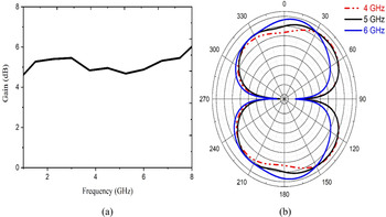
To verify the radiation performance of the antenna at the operating bands, we have simulated the gain and the E-field radiation patterns of the chipless RFID tag system in the adaptation band. The variation of the gain and the E-field radiation patterns for the antenna is shown in Figs 12(a) and 12(b), respectively.
(a) Simulated gain of the RFID system as a function of frequency, (b) E-field radiation pattern of RFID system at different frequencies.

The antenna offers a stable gain performance throughout the operating frequency with a gain of 5.7 dBi. Stable desired radiation patterns in the E-plane are observed for the proposed antenna over the entire operating band in E-field.
Chipless interrogation and backscatter response
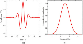
To interrogate the chipless RFID tag, the UWB pulse x(t) is used. It is a modulated Gaussian pulse that has a 20 dB bandwidth of 6 GHz, having frequency content from 2 to 8 GHz, and it can be expressed as follows:

The mean and the standard deviation parameters that define the shape of the envelope Gaussian pulse are: μ = 0.6 ns and σ = 0.114 ns, where the amplitude and the frequency of the sinusoidal signal carrier are respectively: A 0 = 1 and fc = 5 GHz.
The time-domain of the UWB interrogation pulse is shown in Fig. 13(a), and the frequency spectrum of interrogation pulse is shown in Fig. 13(b).
(a) The time-domain of UWB interrogation pulse, (b) frequency spectrum of interrogation pulse.

Analysis of chipless tag backscatter
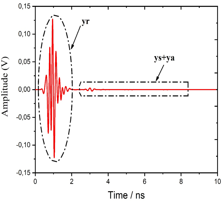
A raised cosine window was used to separate the larger mode and the smaller mode of the received backscatter, as shown in Fig. 14.
Total received signal y(t).

A total time-domain received signal y(t) was obtained through the previously mentioned simulation tool.
The transmission antenna rejects part of the signal, yr(t), which was the first and the largest component of y(t), and it gradually declines and fades away. At the 2.5 ns mark, a small echo was observed, which corresponds to the backscatter that comes from the tag.
Contrarily to the rejected signal, the backscatter was small and cannot be seen clearly in Fig. 14.
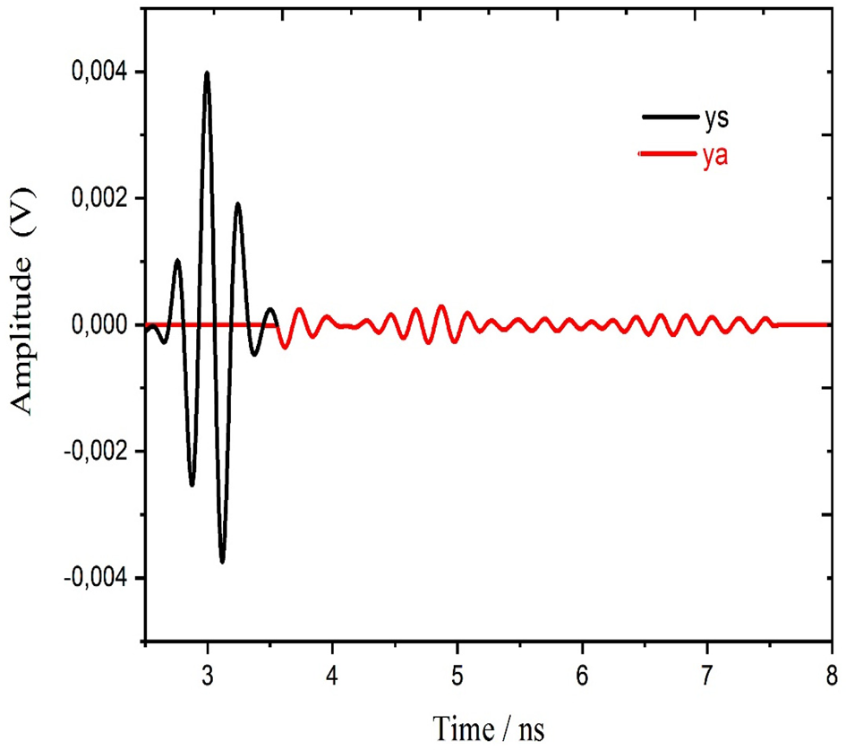
A detailed display of the ys(t) and ya(t) components is shown in Fig. 15.
Enlarged portion of the backscatter showing the structural mode and antenna mode backscatter.

A hypothesis, the larger component corresponds to the structural mode of the backscatter ys(t) and the smaller component was ya(t).
Nevertheless, there was no transmission line that introduces a controlled delay, so it was impossible to clearly define where the structural mode backscatter ends and the antenna mode backscatter starts. To confirm or reject this hypothesis, we need to isolate these components and examine their spectral content.
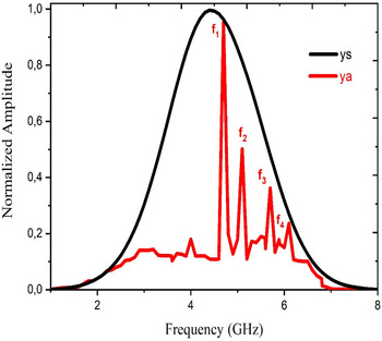
The fast Fourier transform algorithm is used to obtain the spectral content of both windowed structural mode and antenna mode, as shown in Fig. 16. We have used a raised cosine window to nearly approximate ys and ya.
Normalized amplitude spectrum of ys and ya.

We can clearly note that ys(t), the largest and first portion of the backscatter, spectrum is Gaussian and it is similar to the transmitted UWB one, besides, it does not contain information concerning the resonant frequencies. Furthermore, the spectral content of the ya(t) component clearly shows the following resonant frequencies: f 1 = 4.6, f 2 = 5.1, f 3 = 5.7, and f 4 = 6.1 GHz of the individual patch antennas.
Consequently, the transient ya(t) that follows the initial strong backscatter ys(t) was holding the information estimating the resonant frequencies of the patch antennas. We observe also that the peaks corresponding to the resonances are closely following the contour of a Gaussian amplitude spectrum.
A filtered transmitted signal was contained in the antenna mode where uniquely signals corresponding to the resonances appear.
Experimental validation of chipless RFID system
In this section, we discuss the experimental validation of the fabricated tag, which is shown in Figs 2 and 6.
The measurements were realized in an anechoic chamber resorting to a vector network analyzer.
Inside the anechoic chamber, the tag was placed 30 cm away from the reader antenna, and the measurements were taken in the corresponding FD.
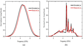
Figure 16 showed the amplitude spectra of the windowed ya and ys. Figure 17 illustrated the measurement results of the amplitude spectrum of ys and ya.
Measured normalized amplitude spectrum, (a) the structural mode ys, (b) the antenna mode backscatter ya.

These results show a good agreement between the measurements and the simulations. A difference of about 0.2 GHz is observed between the measurement and the simulation results, which could be linked to the exclusion zone of dummies not taken into account during the electromagnetic simulation.
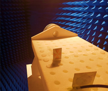
The measurements were carried out in an “electromagnetically” noisy environment. To improve the measurement results, it is possible to design a wooden test bench to support the antennas and allow the manipulator to carry out the measurements freely (Fig. 18). The photo below shows the bench in an anechoic chamber with two antennas facing each other on their supports.
Photo of the test bench, with antennas on their supports.

In the frequency ranges that interest this research, a distance between the antennas of the order of 30 cm was considered.
Conclusion
The main goal of this current research paper is to analyze the backscatter response of an RCS-based chipless tag via a new method. Proceeding with a signal processing technique that combines both time-domain and FD analysis of the backscatter response, the frequency signature of the chipless RFID tag is estimated accurately. After EM simulations, it was shown that the antenna mode of the backscatter contains the information carrying the component of the total received signal. Whereas the structural mode of the backscatter contains no information about the resonant properties of the RCS-based chipless RFID tag. To explain the nature of the backscattered signal and to give an idea about how each component of the whole system contributes to the creation of the total received signal at the reader, an approximation which can be considered as semi-analytical was derived. Measurement results conducted in an anechoic chamber environment have well validated the simulations and the approximations. Our current method can be considered as efficient to successfully estimate the resonant properties of a chipless tag, and that is with no need to use calibration tags.
Acknowledgement
This work was supported by FCT through grant SFRH/BD/116554/2016. The authors would also like to acknowledge all members of the Center for Microelectromechanical Systems Research CMEMS-UMinho.
 Kawther Mekki received her Integrated Master's degree in Electronics, Electrotechnics, Automation from the Faculty of Science of Tunis, El-Manar University, Tunisia in 2016. Currently, she is a Ph.D. student at the Laboratory for Research on Microwave Electronics, University of Tunis El-Manar, Tunisia. Her research interests include the design and development of antennas for chipless RFID tags.
 Omrane Necibi received his M.Sc. degree in Analysis and Digital Processing of Electronic Systems in 2012 and his Ph.D. degree in Sciences and Technology, in 2015, from the Faculty of Science of Tunis, El-Manar University, Tunisia. He is currently an Assistant Professor in the Computer Science Department, College of Arts and Sciences at Tabarjal, Jouf University, Saudi Arabia. His research focuses on the field of wireless communication, in particular radio frequency identification (RFID) with the design and development of antennas for chipless RFID tags.
 Hugo Dinis graduated with the Integrated Master's degree in Biomedical Engineering from Minho University, Braga, Portugal in 2015. Currently, he is a Ph.D. student at CMEMS-UMinho, University of Minho, Braga, Portugal, and an invited assistant at the Department of Industrial Electronics of the same institution. His research interests include wireless power transfer and antenna design for implantable medical devices.
 Paulo Mendes graduated in 1995, and obtained his M.Sc. degree in Electrical Engineering, in 1999, both from the University of Coimbra, Portugal. He obtained his Ph.D. degree in Industrial Electronics, from the University of Minho, in 2005. He is an Associate Professor at the Department of Industrial Electronics, University of Minho, Portugal, and, from 2019, the Director of the Research Center CMEMS (Center for Microelectromechanical Systems). His interest includes micro/nanoelectronics, microsystems, electromagnetics, photonics, RF microelectronics, wireless sensor networks, biomedical devices, wearable devices, antennas and propagation, antenna miniaturization and integration, wireless power, ultrasound waves and systems, RF and MMW materials characterization. Mendes is a Member of the European Microwave Association, of the IEEE Antennas and Propagation Society, and of the IEEE Engineering in Medicine and Biology Society.
 Ali Gharsallah received the Radio Frequency Engineering degree from the Higher School of Telecommunication of Tunis, Tunis, Tunisia, in 1986, and the Ph.D. degree from the Engineering School of Tunis, Tunis, Tunisia, in1994. Since 1991, he has been with the Faculty of Sciences of Tunis, Department of Physics, University El-Manar, Tunis, Tunisia. He is also a Full Professor of electrical engineering and Director of Engineering with the Higher Ministry Education of Tunisia. He has authored or coauthored approximately 100 papers published in scientific journal and 120 conference papers. He has also supervised over 20 theses and 50 masters. His current research interests include smart antennas, array signal processing, multilayered structures, and microwave-integrated circuits. He is an IEEE Senior Member.