NOMENCLATURE
- X = [x y z]T
position vector w.r.t the inertial frame, m
- Ω = [p q r]T
body axes Euler rates vector, rad/s
- u f
total thrust input, N
- τ = [τ φ τ θ τ ψ]T
torque inputs vector, N.m
- φ, θ, ψ
Euler angles w.r.t the inertial frame, degrees
- ω i
motor i speed, rpm
- m
mass of the UAV, Kg
- g
acceleration due to gravity, m/s 2
- J r
propeller inertia, Kg.m 2
- e 3
unit vector along the z axis
- S(.)
skew symmetric operator
- J = [I xx, I yy, I zz]
inertia matrix, Kg.m 2
 $\mathcal{R}$
rotation matrix
- F ij
resultant thrust of two coaxial motors i and j
- F i
thrust produced by the motor i
- τ i
torque produced by the motor i
- ω r
residual propeller speed, rpm
- (·)
time derivative
1.0 INTRODUCTION
Over the last decades, the number of applications benefiting from unmanned aerial vehicles has increased considerably. Their introduction into the airspace leads to a number of safety issues. These include both safety issues on ground level to prevent UAVs from falling and injuring people and/or damaging property, and safety issues in the air to prevent mid-air collisions. Thus new generations of these vehicles must be designed to accomplish their work not only with high efficiency, but also with increased safety and security. First, they are required to have an effective standardised collision avoidance system that guarantees that the UAV can identify and be identified within the shared airspace and avoid risks to the surrounding traffic(Reference Mahjri, Dhraie and Belghith1). On the other hand, they should be equipped with fault-tolerant control systems (FTCSs) that enable the vehicle to continue operating correctly in the event of errors.
The implementation of fault tolerance requires redundancy in the system. An octorotor is an example of a multirotor UAV characterised by a built-in hardware redundancy, and will be taken as a case study in this paper. For a conventional quadrotor, complete loss of a rotor results in a vehicle that is not fully controllable. Partial failures of quadrotor actuators are investigated in(Reference Chamseddine, Zhang, Rabbath, Join and Theilliol2,Reference Avram, Zhang and Muse3) for system recovery and in(Reference Avram, Zhang and Muse4) and(Reference Chen, Jiang, Zhang, Jiang and Tao5) for fault detection and diagnosis. Up to three complete actuators failures are considered in(Reference Mueller and D’Andrea6) where relaxed hover solutions are proposed to allow a multirotor to maintain flight in spite of extreme centre of mass offsets while rotating at a constant velocity in hover.
Actuator redundancy available in an octorotor can be exploited, when an actuator fails, to re-allocate correctly the control effort among the healthy ones in order to retain complete controllability allowing the UAV to complete its mission.
The fault tolerant control of this type of vehicles has been recently studied and different strategies have been proposed: Linear Parametric Varying- (LPV-) based sliding mode control allocation(Reference Alwi and Edwards7), neural network interval type-2 fuzzy sliding mode controller(Reference Zeghlache, Saigaa and Kara8), integral sliding mode scheme combined with fixed control allocation(Reference Alwi, Hamayun and Edwards9), and cascade inverse method of control allocation(Reference Marks, Whidborne and Yamamoto10).
All the fault-tolerant control papers cited above presented numerical simulations on an octorotor UAV in order to validate the proposed strategies.
This paper considers the problem of actuator redundancy management of a coaxial octorotor after failures resulting from complete loss of actuator effectiveness. Its contribution is twofold. First, it extends our previous works presented in(Reference Saied, Lussier, Fantoni, Francis and Shraim11) and(Reference Saied, Lussier, Fantoni, Shraim and Francis12) and validates in real flights three fault tolerant control architectures, two active and one passive, for a multirotor UAV:
Active fault-tolerant control based on Inertial Measurement Unit for fault diagnosis and rule-based control mixing for system recovery;
Active fault-tolerant control based on motors speeds sensing for fault diagnosis and Pseudo-Inverse Control Allocation for system recovery;
Passive fault-tolerant control based on robust super-twisting sliding mode controller.
Second, the paper presents a comparative study of the proposed active and passive techniques from the viewpoint of technical, practical and theoretical performance. The main concern of this paper is to deal with some practical significant considerations in fault diagnosis and fault tolerant control of redundant multirotor UAVs such as tuning, complexity of design, real-time applicability, robustness, etc. It provides also an objective assessment of active and passive fault tolerant control methodologies applied on multirotor UAVs in a comparative setting. The comparison is carried out with real data from the Robotex coaxial octorotor of the Heudiasyc Laboratory, France.Footnote 1
The remainder of the paper is organised as follow. Section 2 presents the octorotor UAV: octorotor model, octorotor reconfigurability analysis and experimental platform. Section 3 presents the fault-tolerant control strategies: concepts, design and experimental results. These results are compared and discussed in Section 4. Concluding remarks with future work are finally given in Section 5.
2.0 OCTOROTOR UAV
The implementation of a FTCS requires the existence of redundancy in the system: hardware, software, information or time redundancy. An octorotor UAV has actuators redundancies, which make it an ideal system for FTC studies.We present in this section the equations of motion of the octorotor. A controllability analysis after actuators failures is investigated based on the distribution of the motors on the arms.
2.1 Octorotor model
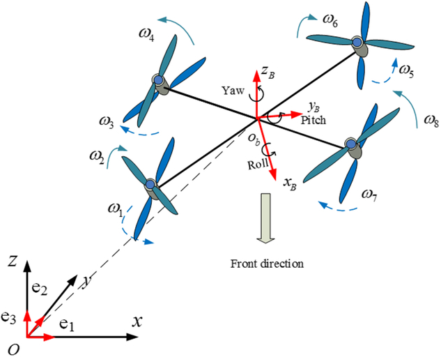
An octorotor UAV is a 6-Degrees Of Freedom (DOF) rigid body that consists in eight motors on which propellers are fixed as shown in Fig. 1. They are attached at the ends of arms under a symmetric frame.
The coaxial counter-rotating octorotor and the reference frames.
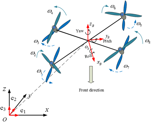
The state variables chosen to model the dynamics of the octorotor are the position and the altitude X = [x y z]T, in the inertial frame, the translational velocities  $\dot{X}$, the Euler angles (φ, θ, ψ) and the angular velocities Ω = [p q r]T. The total thrust F = [0 0 u f]T, the roll, pitch and yaw torques τ = [τ Φ τ θ τ ψ]T are the virtual control inputs, while the motors speeds
 $\omega_{i,_{i=1...8}}$ are the real inputs. Using the Newton-Euler formalism, the nonlinear model of the octorotor UAV is obtained as follows:
 \begin{equation}\left\{\begin{array}{l}m\ddot{\mathcal{X}}=-mge_3+\mathcal{R}F \\ \dot{\mathcal{R}}=\mathcal{R} \mathcal{S}(\Omega) \\ J \dot{\Omega}+\mathcal{S}(\Omega)J\Omega=\tau \end{array}\right.\end{equation}
S(.) is the skew-symmetric operator and J is the inertia matrix. The orientation of the octorotor with respect to the inertial frame is represented by the rotation matrix  $\mathcal{R}$. The thrusts of the propellers are related to the virtual inputs as in (2) with F ij being the resultant thrust of two coaxial motors i and j (Reference Saied, Lussier, Fantoni, Francis and Shraim11) and τ i the torque produced by the motor,
 $F_i=k_f \omega_i^2$ and
 $\tau_i=k_t \omega_i^2$:
 \begin{equation}\left\{\begin{array}{l}u_f=F_{12}+F_{34}+F_{56}+F_{78} \\ \tau_\phi=(F_{78}+F_{56}-F_{34}-F_{12})l\sqrt{2}/2 \\ \tau_\theta=(F_{34}+F_{56}-F_{78}-F_{12})l\sqrt{2}/2 \\ \tau_\psi=(\tau_2+\tau_3+\tau_6+\tau_7)-(\tau_1+\tau_4+\tau_5+\tau_8) \end{array}\right.\end{equation}
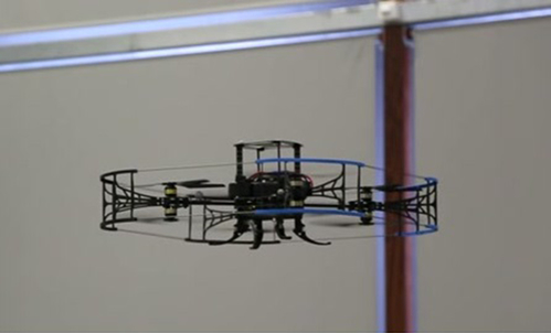
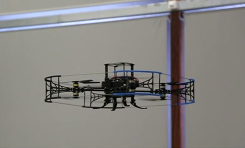
The chosen platform for our experiments is the Modul-Air octorotor shown in Fig. 2 and built at Heudiasyc laboratory, University of Technology of Compiègne in France(Reference Saied, Lussier, Fantoni, Francis, Shraim and Sanahuja13). Its parameters are given in(Reference Saied, Lussier, Fantoni, Francis and Shraim11). In the next sections, passive and active FTCS will be tested on this octorotor. Only actuator failures are considered in this study due to their impact on the UAV stability.
The experimental octorotor UAV.
2.2 Reconfigurability analysis
The analysis of the dynamics stabilisation of a multirotor UAV starts with the definition of the necessary and sufficient conditions for the system controllability and the control reconfigurability. An octorotor UAV is a nonlinear system with positive control inputs since the rotors only provide a unidirectional thrust. Thus classical controllability theory(Reference Sontag14) will have a major limitation if applied to this system: the unilateral constraints do not pass the Kalman Rank test. A slight modification of this test, however, can account for these constraints.
Consider a linear time invariant system written as:
 \begin{equation}\dot{x}(t)=Ax(t)+Bu(t)\end{equation}
with x(t) ∈ R n.The rank condition for the controllability matrix M c = [c 1 c 2 … c m]T = [B AB … A n−1B]T can be expressed as:
 \begin{equation}{Rank} (\{\alpha_1 c_1 + \alpha_2 c_2 + ... + \alpha_m c_m | \alpha_1, \alpha_2,...,\alpha_m \in R\})=n \end{equation}
To include the unilateral constraints, this condition is simply modified to a positive span,
 \begin{equation}{Rank}(\{\alpha_1 c_1 + \alpha_2 c_2 + ... + \alpha_m c_m | \alpha_1, \alpha_2, ..., \alpha_m \in [0,\infty)\})=n\end{equation}
Considering the attitude system of the octorotor with  $x(t)=[\phi \: \dot{\phi} \: \theta \: \dot{\theta} \: \psi \dot{\psi}]^T$ and
 $u(t)=[\omega_1^2 \: \omega_2^2 \: ... \: \omega_8^2]^T$, the application of the modified Kalman test shows that the octorotor is not fully controllable when the two failed motors are not diagonally opposing while rotating in the same direction or when they are coaxial motors(Reference Saied, Shraim, Lussier, Fantoni and Francis15).
3.0 FAULT-TOLERANT CONTROL STRATEGIES
Fault-tolerant control aims at ensuring that the system’s behaviour stays correct despite the occurrence of faults and subsequent errors caused in the system. Generally speaking, fault tolerant control systems can be divided into two types: those that detect errors in the system and recovers from them (e.g. through reconfiguration or control allocation techniques) are known as active fault-tolerant control systems (AFTCSs), and those that tolerate faults without error detection (for example through robust control) are known as passive fault-tolerant control systems (PFTCSs).
3.1 Active fault-tolerant control design
An AFTCS typically consists of a Fault Detection and Diagnosis (FDD) scheme, a reconfigurable controller, a controller reconfiguration mechanism and a command/reference governor(Reference Zhang and Jiang16). Based on this architecture, the design objectives of an AFTCS are to design: (1) an FDD scheme with high sensitivity to faults that will not trigger false positive from model uncertainties and external disturbances; (2) a controller which can easily be reconfigured; (3) a reconfiguration mechanism which leads as much as possible to the recovery of the pre-fault system performance after failures occurrence, or at least to a degraded mode that ensures the safety of the system and its environment.
The critical issues in any AFTCS are the limited amount of time available for the FDD to detect and identify the error, the accuracy of the fault identification and the time taken to synthesise and deploy the new control schemes.
3.1.1 Design of fault detection modules
For this paper, we develop two different FDD modules for actuators failures: the first one uses the Inertial Measurement Unit to detect uncontrolled movements of the UAV; the second one is based on the direct supervision of the motors speed and current.
(a) Design of a model-based FDD
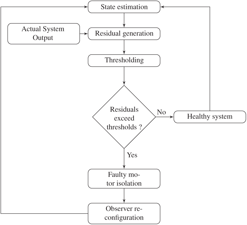
Model-based fault diagnosis is defined as the detection, isolation and identification of faults from the comparison of a system available measurements, with a priori information represented by the system mathematical model. Fault detection is supported by thresholding applied on residuals generated from the difference between real and estimated measurements. A set of residuals must be designed, where each one is sensitive to a subset of faults. Model-based FDD comprises two main stages, residual generation and evaluation. For the octorotor case, residuals are generated using a nonlinear sliding mode observer; then they are evaluated according to the angles signature of each motor. The fault detection and isolation strategy is illustrated in Fig. 3.
Fault detection and isolation algorithm.

Residual Generation: Residuals are constructed using Euler angles and their corresponding angular velocities. They are functions of the difference between real and estimated outputs:
 \begin{equation}r_k=y_k-\hat{y}_k, \: \: \: \: \: k=1,2,3.\end{equation}
Real outputs y k are given by an Inertial Measurement Unit and estimated outputs  $\hat{y}_k$ are deduced from a super-twisting sliding mode observer whose equations are given below:
 \begin{equation}\begin{array}{l}\dot{\hat{x}}_1=\hat{x}_2+z_1 \\ \dot{\hat{x}}_2=f(t,x_1,\hat{x}_2,u)+z_2 \end{array}\end{equation}
with x 1 = [φ θ ψ]T,  $x_2=[\dot{\phi} \: \dot{\theta} \: \dot{\psi}]^T$ and
 \begin{equation}f=\left[ \begin{array}{c}\frac{I_{yy}-I_{zz}}{I_{xx}}\dot{\theta}\dot{\psi}-\frac{J_r}{I_{xx}}\dot{\theta}\omega_r+\frac{1}{I_{xx}}\tau_\phi \\ \frac{I_{zz}-I_{xx}}{I_{yy}}\dot{\phi}\dot{\psi}+\frac{J_r}{I_{yy}}\dot{\phi}\omega_r+\frac{1}{I_{yy}}\tau_\theta \\ \frac{I_{xx}-I_{yy}}{I_{zz}}\dot{\phi}\dot{\theta}+\frac{1}{I_{zz}}\tau_\psi \end{array} \right]\end{equation}
is the nonlinear part of the attitude model. J r is the propeller inertia and ω r is the overall residual propeller speed from the unbalanced rotors rotation:
 \begin{equation} \omega_r=\omega_2+\omega_3+\omega_6+\omega_7-\omega_1-\omega_4-\omega_5-\omega_8\end{equation}
z 1 and z 2 are output injections given by the equations below using a low-pass filter(Reference Davila, Fridman and Levant17):
 \begin{equation}\begin{array}{l}z_1=\lambda |x_1-\hat{x}_1|^{\frac{1}{2}} \mbox{sign}(x_1-\hat{x}_1) \\ z_2=\alpha \: \mbox{sign}(x_1-\hat{x}_1) \end{array} \end{equation}
α and λ are matrices of positive gains that guarantee the finite-time convergence of the observer.
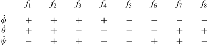
Residual Evaluation: Residuals are examined for the verisimilitude of faults using thresholding method. According to (2) all residuals are affected once a failure of any of the actuators occurs. The first time they go above the threshold level, the fault is supposed to be present. A diagnosis inference model, based on the analysis of the failure modes, is presented in Table 1(Reference Saied, Lussier, Fantoni, Francis, Shraim and Sanahuja13), and the algorithm in (11) is used to detect the failure of one motor.
 \begin{equation} \begin{array}{ll}\mbox{if} \: \:(r_i>threshold_i) \\ \{\mbox{if} \: (\dot{\phi}<0 \: \&\: \dot{\theta}<0 \: \& \: \dot{\psi}<0)\} \\ \mbox{then motor 6 in failure}\end{array}\end{equation}
Diagnosis inference model for one rotor failure

(b) Design of a hybrid FDD
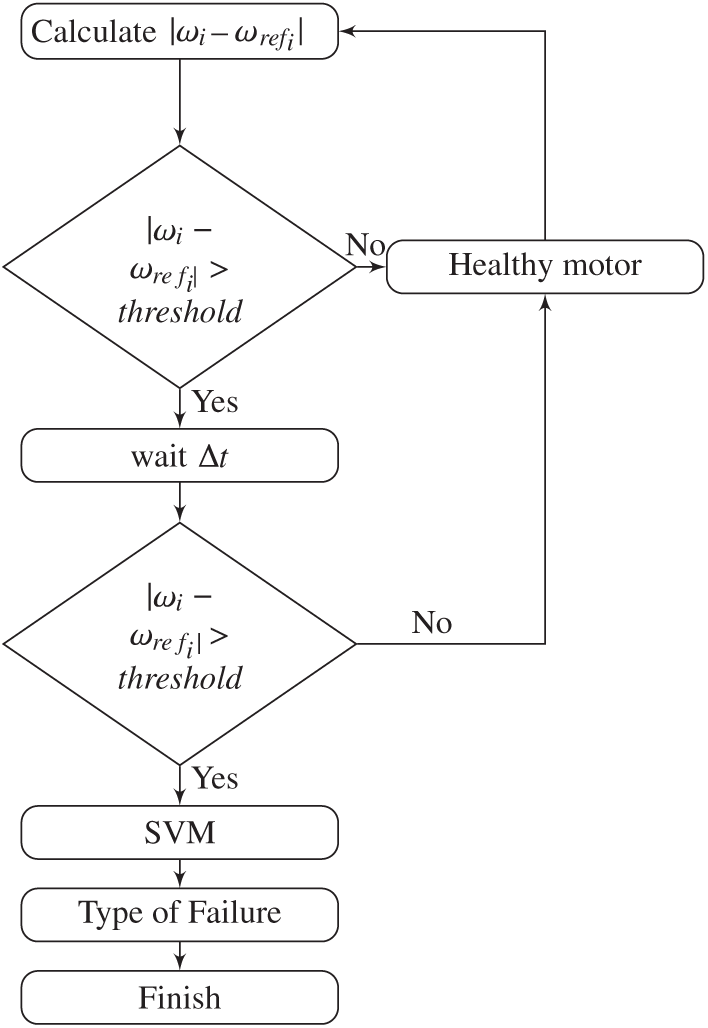
Model-free approaches rely on historical data collected from sensors and measurements, without a need for a detailed mathematical model of the system. In this section, we present a combination of a model-based thresholding and a model-free classification where the fault diagnosis is carried out in two stages. The measured motor speed and the desired speed estimated from the control laws outputs are first compared. If they are not equal for a fixed amount of time, the motor is said to be failed. Its speeds and currents are then used as input data for a support vector machine block to classify faults as propeller loss or motor failure. The FDD diagram is shown in Fig. 4.
Hybrid fault diagnosis diagram.

DC Motor Modeling: The equations governing the operation of a Brushless Direct Current BLDC motor with speed ω M are given below in Laplace transform:
 \begin{equation}\begin{array}{c}I(s)=\frac{-K_v \omega_M(s)+V(s)}{Ls+R} \\[7pt]\omega_M(s)=\frac{K_TI(s)-T_L(s)}{Js+B_M}\end{array}\end{equation}
I, V, R and L are the armature current, voltage, resistance and inductance. K v and K T are respectively the back-electromotive and torque constants. J r and B M represent the inertia of the rotor and the damping coefficient and T L the load torque. When the motor stops rotating, i.e. ω M, the armature current, I(t) = V(t)/R, will reach the maximum value for a given input voltage V. However, this is not true when simulating a motor failure, since we inject the fault by adjusting the motors voltage and current to zero. With no propeller attached on the motor, the speed will increase with a decrease in the current (12).
Support Vector Machine (SVM): Support Vector Machines(Reference Vapnik18) are supervised learning models that can perform pattern recognition and classification problems. In this application, a SVM classifier is used to discriminate between propeller loss and motor failure. Only two features are to be used: the electrical current and the speed of the motor. Different experiments were carried out to collect these measurements before, during and after a propeller loss or a motor failure. The gathered data are trained using a C type SVM with a radial basis kernel.
(c) Performance evaluation of both FDD techniques
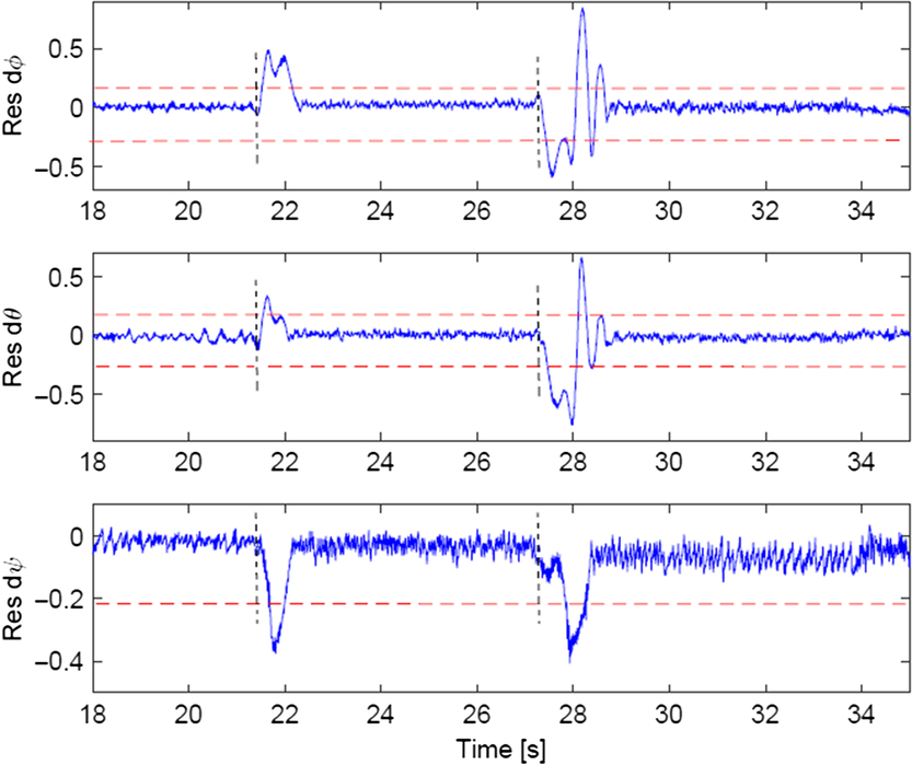
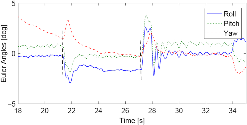
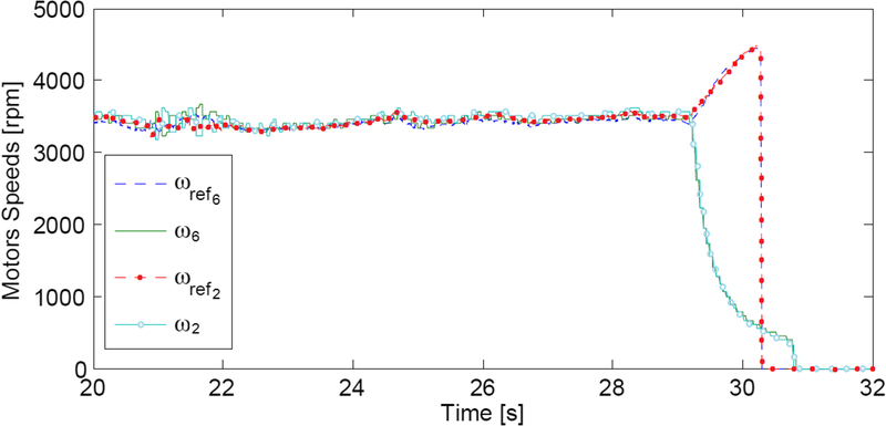
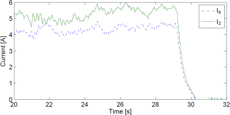
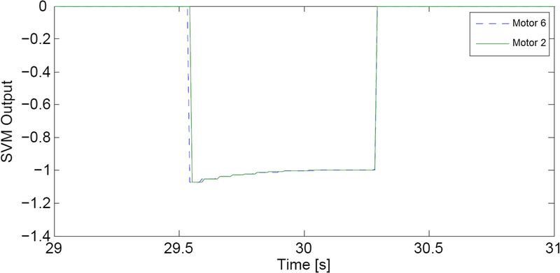
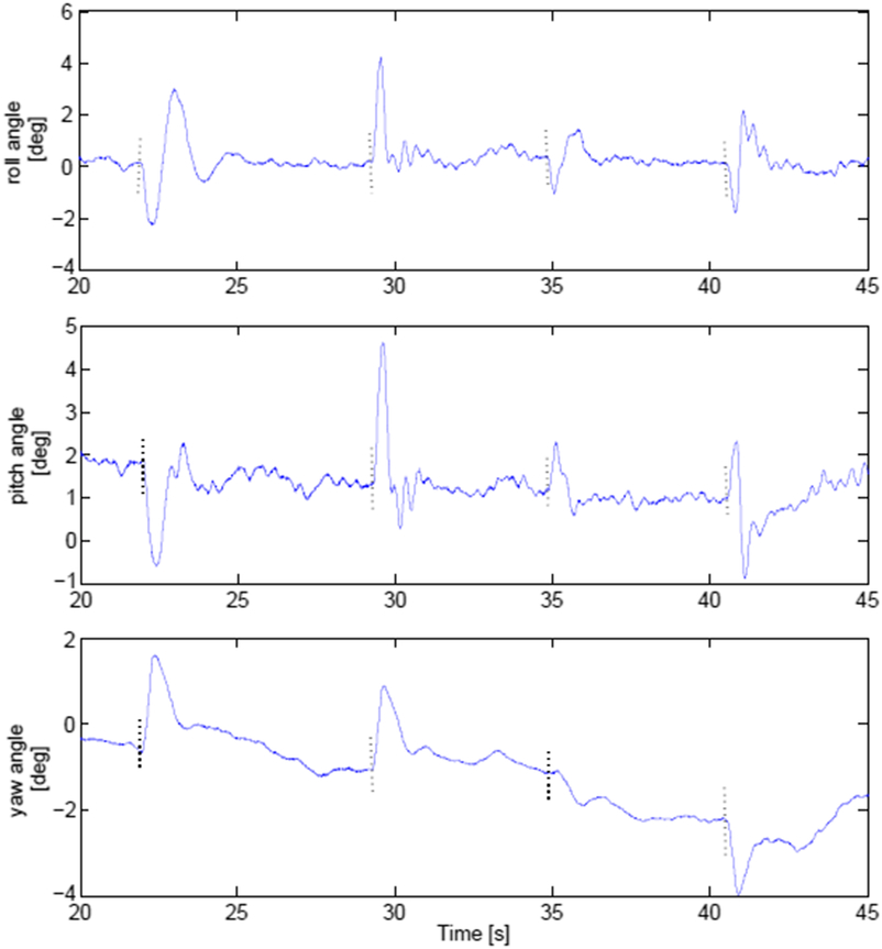
Experimental Validation: The proposed FDD modules are validated experimentally using fault injection. Failures on actuators 6 and 2 are simulated when the octorotor was hovering around equilibrium. The position controller uses information from a motion capture system. For the first FDD module, Figs. 5 and 6 show respectively the residuals and orientation of the octorotor after the motors failures. The failures are injected respectively at times 21.37s and 27.19s, and isolated at times 21.65s and 27.82s, corresponding to detection delays of 0.28s and 0.63s. For the second FDD module, motors 6 and 2 are stopped simultaneously at time 29.18s. The motor will no longer track its reference speed as in Fig. 7 and the SVM prediction algorithm is triggered. Figure 8 shows the variations of the armature current, and Fig.9 shows the SVM outputs (negative) corresponding to a motor failure. The detection delay is 0.36s.
Residuals on angular velocities after consecutive motors failures.

Euler angles after two consecutive motors failures.

Motors speeds and their references during hovering flight after two simultaneous motors failures.

Motors currents during hovering flight after two simultaneous motors failures.

Diagnosis block output after two simultaneous motors failures.

Comparison: Generally speaking, it is not easy to compare fault detection schemes. The selection of a specific fault detection strategy depends upon several factors including characteristics of the process itself (linear or nonlinear, time-varying or time-invariant), the validity of the process model, and the application sensitivity. For critical applications, model-free approaches are usually not recommended, as we have no guarantee that they will perform correctly in all situations(Reference Sari19). Model-based approaches are preferred because their models and designs can be validated in the operation domain. In our case, we only used a model-free approach to distinguish between two types of faults. The fault detection and the failed component identification were realised by a thresholding method, based on an electrical model of the motors, and are sufficient to perform system recovery.
For the special case of an octorotor UAV, detecting motor or rotor faults directly using the motor controller offers several advantages, as each motor can be considered as an auto-testable component:
Only the motor/propeller model is necessary. The FDD module is then insensitive to the payload changes and the external disturbances;
It offers possibilities of detecting simultaneous faults since each motor is evaluated separately.
The main drawback of this method is the necessity of additional sensors to obtain motors information.
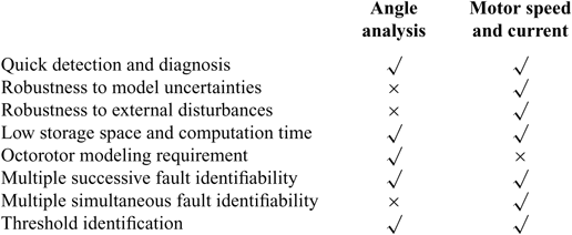
The proposed model-based FDD based on angle analysis makes use of the inertial measurement unit only, without need of any additional sensors. Although it shows good results during hovering flight after one or multiple successive failures, this model-based FDD is sensitive to external disturbances. In addition, it is not possible, using only the angular velocities, to isolate two or more simultaneous failures.
The performance criteria used to compare the two FDD methods are summarised in Table 2.
Comparison of the two FDD methods

Other performance criteria could be also used to compare the two FDD methods such as Diagnosis resolution and Error rate. The diagnosis resolution represents the average number of valid fault hypotheses per diagnosis, and the best possible value is 1. The error rate of a diagnosis system is defined as the average percentage of wrong diagnoses. An error rate of 0 is desirable. It is not easy to quantify these two variables in an experimental environment where parameters of both methods are optimised in a way to reach the optimal point in the error rate/diagnostic resolution-plane, (0/1). However, according to the previous comparison in terms of sensitivity to disturbances and uncertainties, one can deduce that the method based on motors information will probably be better in terms of error rate and diagnosis resolution, when considering missions specifications different from what was considered during our experiments (e.g. aggressive maneuvers, outside flights), since these specificities will have more effects on the system’s orientation than on the motors’ speeds and currents.
3.1.2 Design of system recovery techniques
We consider in this section two system recovery techniques: control allocation and control mixing.
(a) Design of a system recovery based on pseudo-inverse control allocation
The control allocation problem appears when the controlled system has more physical actuators than control objectives(Reference Boskovic and Mehra20). Its design consists of several levels: (a) A high level motion control algorithm to calculate the virtual inputs of the system. (b) A control allocation algorithm to map the vector of these desired inputs into individual effector forces or moments. (c) A separate low-level controller to control the actuators. For a multirotor UAV, four control objectives must be met (the thrust, the roll, pitch and yaw) using the available actuators. After one or multiple actuator failures, the control effect can be re-allocated to the remaining working actuators by the control allocation system without any need to reconfigure or re-design the controller. The pseudo-inverse is one the most used methods to solve unconstrained linear control allocation problems. Neglecting any constraints on the input, and giving that τ = Bu, the control signal u is then written as:
 \begin{equation} u=\left[W^{-1}B^T(BW^{-1}B^T)^{-1}\right]\tau\end{equation}
with W = diag{w 1 … w 8} representing the effectiveness of the individual rotors and 0 < w i < 1. τ and u are defined previously. The fixed matrix B is deduced from (2).
(b) Design of a system recovery based on offline rule-based control mixing
A nonlinear constrained optimisation approach is proposed to be used in order to calculate offline the solutions to a predefined set of failures and store them in a lookup table. During the UAVs operation, the proper control mixing law is chosen according to the decision of the FDD module. This method presents the advantage of being facilely tested and validated before the first vehicle flight. The optimisation problem is formulated as:
 \begin{equation}\begin{array}{ll}\: & \min_u \frac{1}{2} u^T u \\\mbox{such that:}& \left\{ \begin{array}{l}u_{min}<u<u_{max}\\[4pt]Bu=\tau \\\end{array} \right.\end{array}\end{equation}
with τ, B and u are as defined in the previous section. u max depends on the occurring failure. Equation (6) is solved using the Matlab’s multi-parametric programming tool. Based on the solution obtained, the control mixing gains are deduced for each failure case.
(c) Performance evaluation of the AFTCS
Performance criteria: The following indices will be used for the performance evaluation of the different FTCSs:
The mean and maximum values of the tracking error;
The settling time after fault injection;
The control input energy;
The practical applicability.
The reference tracking error is evaluated using the following measure:
 \begin{equation}e(t)=||r(t)-y_{ftc}||,\end{equation}
where r(t) is the reference signal and y ftc is the system output with fault tolerance applied. Other performance indices can also be used such as the mean and the maximum value of e(t), t ∈ [t 1, t 2], with t 1 being the fault injection time, and t 2 the settling time of the control output with respect to the reference signal after the fault injection:
 \begin{equation}\begin{array}{l}\bar{e}=\frac{1}{t_2-t_1}\int_{t_1}^{t_2}e(t)dt \\ e_{max}=\displaystyle \max_{t_1\leq t \leq t_2}\{e(t)\} \end{array}\end{equation}
For comparison, the longest settling time for a FTCS is selected for calculations.
The settling time is the time required for the state variables to return and remain within a range of certain percentage of their reference values. Since we are studying a real system response, we consider a percentage of 5% to determine the settling time.
The control input energy represents the mean value of energy of the control input signalu(t):
 \begin{equation}E=\int_{-\infty}^{\infty} |u^2(t)|dt\end{equation}
In all the tables below, the control input energy is evaluated only in the interval [t 1, t 2] defined previously.
Unlike the other indices presented above, which are quantitative, practical applicability is a qualitative performance criterion. It consists of evaluating the possibility of real-time implementation and the difficulties that can be faced when a fault-tolerant control strategy is applied on the system.
For the AFTCSs, an extra issue has to be considered: the time needed for the finalisation of the controller reconfiguration after the fault occurrence. However, the uncertainty associated with the FDD decision will not be considered since we are considering only complete actuator failures.
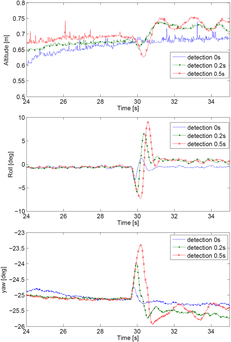
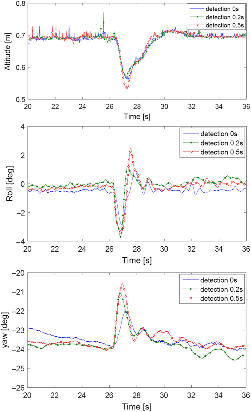
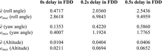
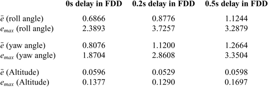
Performance evaluation: The evaluation of the AFTCSs is done under different FDD time delays (0s, 0.2s and 0.5s). Since the response depends also on the fault injection time, all motors failures are injected once the UAV reaches the altitude reference and its attitude is stabilised around the equilibrium. Due to space limitations, only the responses in the roll (similar to the pitch response due to the system symmetry), the yaw and the altitude are illustrated in Figs. 10 and 11. Evidently, the performance of the multirotor deteriorates with the increase in FDD delays, assuming a perfect fault estimation. The results of real time flights are summarised in Tables 3 and 4. The AFTCSs without FDD delay produce  $\bar{e}$ and e max of 0.6866 and 2.3893 using the reconfigurable control mixing method, and of 0.4717 and 2.8618 using the pseudo-inverse control allocation. Results are obviously worse with longer detection delays.
Responses of pseudo-inverse control allocation under three different FDD delays.

Responses of reconfigurable rule-based control mixing under three different FDD delays.

Performance indices of the AFTCS based on pseudo-inverse control allocation after one motor failure and under three time delays

Performance indices of the AFTCS based on reconfigurable control mixing after one motor failure and under three time delays

3.2 Passive fault-tolerant control design
PFTCSs generally make use of only one robust controller, that deals with all the expected faults, without on-line fault information neither controller parameters reconfiguration. The main purpose is to develop a controller that makes the system insensitive to design basis faults. The critical issues in any PFTCS are first its reliability for the class of failures beyond design basis, and second the compromise between the nominal and the faulty performances. Note that a well-known disadvantage of fault masking is that, as system errors are not detected, the fault masking can exceed its fault tolerance limit without warning, causing an unexpected failure of the whole system.
3.2.1 Design of a PFTCS
Different passive FTC methods have been suggested in the literature, principally based on robust theory, e.g. H∞, nonlinear regulation theory, Lyapunov and passivity-based FTC(Reference Benosman21). It was proved in(Reference Alwi, Hamayun and Edwards9) that Sliding Mode Control (SMC) has the ability to retain the desired performance without requiring fault detection and isolation. Sliding Mode Control is a non linear robust state feedback control technique that uses switching control actions(Reference Edwards and Spurgeon22). It offers several advantages in terms of low sensitivity to parameter uncertainties and external perturbations. This property makes it an excellent candidate for passive fault-tolerant control system.
The SMC presented here is based on the work introduced in(Reference Derafa, Benallegue and Fridman23). It is a second order technique known as Super-Twisting Algorithm (STA). The design of this SMC for the coaxial octorotor starts by defining the state vector x: x 1 = [z φ θ ψ]T,  $x_2=[\dot{z} \: \dot{\phi} \: \dot{\theta} \: \dot{\psi}]^T$ and x = [x 1 x 2]. The model describing the altitude and the attitude of the system is written as in (18) with w(t) = [w 1 w 2 w 3 w 4]T being the external disturbances vector:
 \begin{equation}\left\{ \begin{array}{l}\dot{x}_1 = x_2 \\ \dot{x}_2 = F(x) + G(x) u + w(t) \end{array} \right.\end{equation}
Different assumptions are considered: the state vector can be measured by sensors, the velocity and the acceleration of the UAV are bounded and the aggressive behaviour is not authorised. Under these constraints, the matrix is invertible, and the disturbances vector is bounded:
 \begin{equation}|\dot{w}_i(t)|<\delta_i\end{equation}
The sliding surface is chosen as:
 \begin{equation} s=\dot{e}+\lambda e\end{equation}
with e = x 1d − x 1 and  $\dot{e}=x_{2d}-x_2$ being the tracking errors, and λ is a positive definite matrix. The control that guarantees that the system remains on the sliding surface can be found as:
 \begin{equation}\tau = G^{-1}(\ddot{x}_{1_d} - \lambda \dot{e} - K_1 |s|^{\frac{1}{2}} \mbox{sign}(s) - K_2 \int_0^t \mbox{sign}(s(\tau)) d\tau - f(x))\end{equation}
K 1 = diag(k 11, k 12, k 13, k 14) and K 2 = diag(k 21, k 22, k 23, k 24) are the gains matrices that verify:
 \begin{equation}\begin{array}K_{2i} > \delta_i \\ K_{1i}^2 > 4K_{2i}\end{array} \: \: \:\begin{array}i = 1,2,3,4 \end{array}\end{equation}
The convergence proof is given in(Reference Derafa, Benallegue and Fridman23).
Normally, the main disadvantage of the sliding mode controller is the chattering: finite amplitude high-frequency oscillations of the controlled structure. However, the higher order sliding mode technique, which is a generalisation of the first order sliding mode control with higher order derivatives of the sliding variable, reduces this undesirable phenomenon.
3.2.2 Performance evaluation of the PFTCS
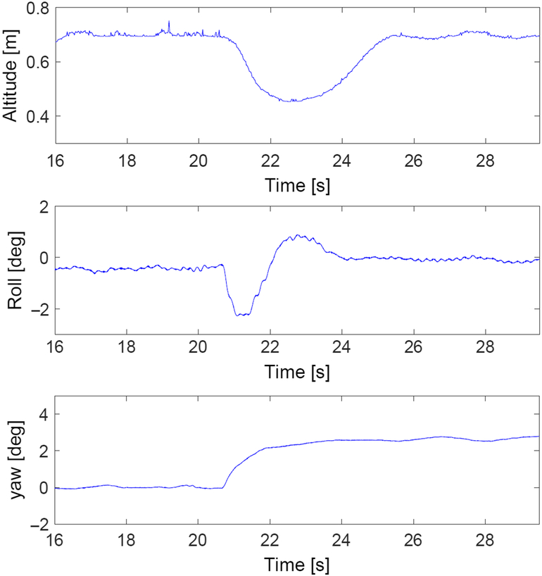
As for the AFTCS case, a failure on motor 6 is injected once the UAV reaches its reference altitude. However, with PFTCS, no FDD nor controller reconfiguration delays need to be considered. The results are presented in Fig. 12 and in Table 5.
Responses of sliding-mode control under one actuator failure.

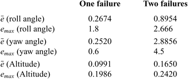
Performance indices of the PFTCS based on robust SMC after one and two failures

4.0 FTCSs COMPARISON RESULTS
In the previous sections, the architectures of both active and passive FTCSs are introduced, and their performances are described. The experimental conditions of the system under AFTCS and PFTCS are chosen in a similar manner. Due to the design techniques used, some aspects of the results may be application-dependent. However, we believe that our general conclusions remain applicable.
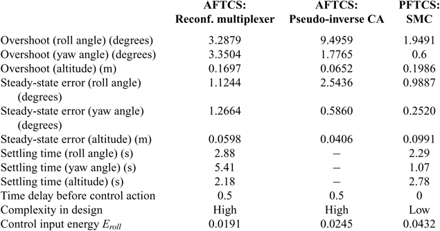
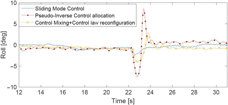
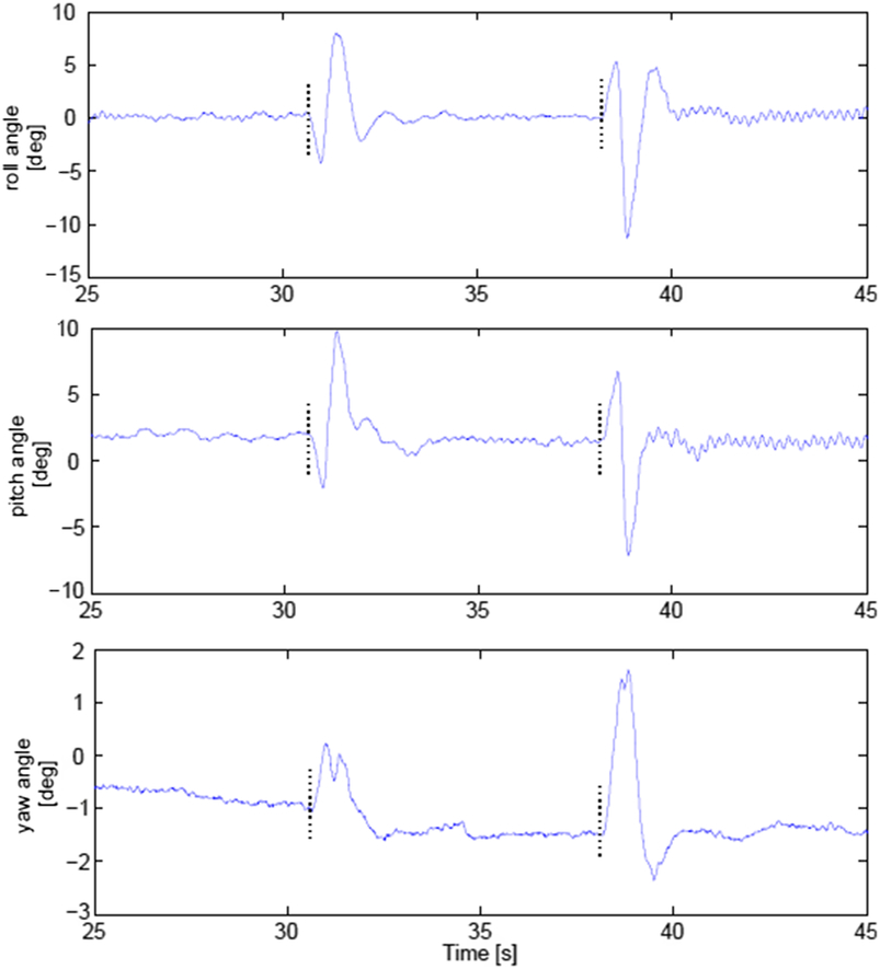
In this study, the AFTCSs analysis assumes a precise diagnosis with a detection delay of 0.5s to focus the comparison on the recovery mechanisms. 0.5s is a rather pessimistic value for detection, guaranteeing under most circumstances a correct fault detection and identification. First, both approaches are designed under case 1: Failure of motor 6. Under this fault condition, the Euler angles deviations resulting from the application of AFTCS and PFTCS are presented in Fig. 13. It is observed that the deviations in the AFTCSs cases have significant values when the reconfigurable controller or multiplexer are activated, which provokes considerable transients. In a PFTCS, the control surface deviations are much smoother, since it does not need to switch to a degraded mode. The performance of the AFTCS and PFTCS are evaluated considering the overshoot, settling time, steady-state error, complexity design and tuning facility as illustrated in Table 6. Other criteria will also be considered such as the applicability and control input energy. Table 6 shows that the FTC scheme using the sliding mode controller achieves better performances in terms of minimal overshoot, steady state error and settling time on the attitude. However, the input energy required by this controller is bigger than in the case of the tested AFTCSs. For the Pseudo-Inverse method, it is shown that using this technique, the steady state error remains greater than 5% of the reference value, and thus no settling time is indicated in the table. The values of $\bar{e}$ and e max are calculated in the interval [t 1, t 2] where t 2 is the longer settling time for the other two techniques. In case of multiple failures, the performance of the robust controller degrades and AFTCSs are shown to be better. In practice, it is possible to tolerate up to four successive or simultaneous motors failures using AFTCS but not more than two motors failures using PFTCS. Figures 14 and 15 show that the AFTCS based on the reconfigurable control mixing is better in terms of overshoot, settling time and steady-state error.
Performance comparison between active and a passive FTCS

Comparison of responses of active and passive FTCS.

Euler angles [deg] after fault injection on motors 6 and 2 using pseudo-inverse control allocation.

Euler angles [deg] after fault injection on motors 6, 2, 8 and 4 using reconfigurable control mixing.

4.1 Advantages and limitations of AFTCS
Once a fault is detected, the AFTCS moves from the nominal mode to a different solution region to act against the fault and reduce its effects. Within each of these regions, the optimal solution may exist with certain pre-determined performance criteria. AFTC is less conservative than PFTC since the fault is treated as a scheduling variable and not an additional uncertainty against which robustness must be enforced. This is shown by the possibility of tolerating more faults using AFTCSs. For the special case of an octorotor, during real applications, the PID controllers are the most used onboard UAVs since they present good performance and are easy to tune. In this context, the AFTCS scheme is able to provide fault tolerance to controllers that are not intrinsically fault tolerant.
The main limitation of an AFTCS is its high dependence on the FDD module outputs. Once an error occurs, no action can be performed until the fault is detected and diagnosed. The interval between the fault occurrence and its detection has a major impact on the maintenance of the stability of the system. As illustrated in Tables 3 and 4 and Figs. 10 and 11, the performance of the system worsens with the increase in FDD time. The reconfigurable mixer or control allocation design depends heavily on the output provided by the FDD scheme. Any wrong decisions in FDD can lead to loss of effectiveness in the system recovery. In both of the presented AFTCS, the switching between the nominal and degraded modes leads to immoderate transients as shown in Figs. 10, 11, and 13. These transients, considered as shocks, can induce further damage in the system.
4.2 Advantages and limitations of PFTCS
The main advantage of a PFTCS is its simple structure. Once designed, the controller does not change and no transients are caused by controller switching operation. The behaviour of the system is much smoother than an AFTCS, as can be seen in Fig. 13. Furthermore, as a fault masking technique, a PFTCS does not need a FDD scheme, thus there is no delay between the fault and the recovery actions.
The robust controller is designed for both normal and post-fault system operation. Thus this solution cannot be optimum for all design scenarios. Moreover, the overall conservatism increases with the number of faults considered during the design stage. For an octorotor, no PFTCS can be found after more than two actuator failures and thus this method presents limited FTC capabilities. The main advantage of the PFTCS is the avoidance of the time delay required for FDD and control reconguration. However, by not detecting faults, successive failures may exceed the FTC capability without warning, causing unexpected failure of the whole system.
5.0 CONCLUSIONS
Although the development of fault-tolerant control strategies is the topic of many works in the multirotor UAVs community, some technical and real-time considerations in application to real multirotors are still missing. Rare are the studies that consider the design of methodologies that involve feasibility and real world requirements specifications.
This paper presents the design and real-time implementation of fault-tolerant control architectures for an octorotor under actuators failures. It deals with some practical considerations in fault diagnosis and fault-tolerant control for such systems including tuning, complexity of design, real-time applicability, etc.
In active FTC systems, both aspects, including fault detection and system recovery, are considered. The passive FTC system capability is based on the robustness of a high-order sliding mode controller. A comparative study between the different proposed techniques, carried out from qualitative and quantitative perspectives, has been also presented in this paper and shows that each technique has its own advantages and limitations. In general, active approaches are more flexible to deal with different types of faults. However, they are highly dependent on the fault detection and identification accuracy and the detection delay. Passive FTC approaches are simpler to be implemented since they do not need neither an FDD scheme, nor a reconfiguration mechanism. However, the main limitation of these approaches is that they can never be optimal for all design scenarios and the overall conservatism increases at the same time as the number of faults considered during the design phase, eventually restraining the set of possible tolerated faults. As a conclusion, the designer of the FTCS of a multirotor should select the appropriate method according to the targeted faults, their mean of detection and the probabilities of multiple failures.
ACKNOWLEDGEMENTS
This work was carried out and funded in the framework of the Labex MS2T (Reference ANR-11-IDEX-0004-02) and the ROBOTEX Equipment of Excellence (Reference ANR-10- EQPX-44). They were supported by the French government, through the program Investments for the Future managed by the National Agency for Research.
The authors would like to thank the Lebanese University research support program.