I. INTRODUCTION
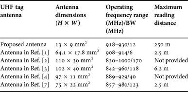
Recently, radiofrequency identification (RFID) systems have received considerable attention and have been used in a wide range of applications, such as object identification, livestock tracking, access control, point of sale, and supply chain management. A number of frequency bands are assigned to the RFID technology: 125/135 KHz (low-frequency (LF) band), 13.56 MHz (high-frequency (HF) band), 860–960 MHz (ultra-high-frequency (UHF) bands), 2400–2485 and 5725–5875 MHz (microwave bands (MW)). Moreover, UHF-band RFID systems particularly provide long-range, faster reading, and larger information storage capability performance than those operated in the LF and HF bands. Additionally, in the passive RFID system, no battery is involved in the tag only excited by the incoming electromagnetic power from the reader antenna. The tag antenna is a key to the RFID receiving and back-scattering systems. Consequently, an increased interest for UHF RFID tag antenna technology has arisen recently to assure good communication qualities such as the longer detection range and high accuracy. Numerous tag antennas for UHF RFID systems have been developed and include the symmetrical dipole antenna to increase the operating bandwidth [Reference Choi, Kim, Kim and Choi1–Reference Xu, Hu and Wang3]; meander antennas to reduce the antenna's dimensions [Reference Bae, Lee, Chang, Kwon and Yoon4–Reference Rida, Yang, Basat and Tentzeris6], a planar compact inverted-E tag antenna with dual-resonant modes [Reference Lu and Hung7], the F-shaped dipole antenna [Reference Lu and Wu8], the loop antenna with a pair of rectangular parasitic patches [Reference Lu and Su9], the dual-branch dipole antenna with a shorting pin [Reference Lu and Zheng10] and the dual-meander-dipole antenna with a square loop [Reference Lu and Siao11]. For active RFID applications, many pioneer designs have been proposed such as a slotted patch composed of a feeding microstrip line and a foam spacer [Reference Chang, Wang, Zhang, Li and Feng12] and a dual-band coplanar-waveguide-fed transparent antenna [Reference Malek, Hakimi, Abdul Rahim and Evizal13]. However, a common limitation is their large size. However, the demand for a compact tag antenna for RFID systems is also growing. Thus, in this paper, by introducing an L-shaped plate connecting with the spiral monopole antenna, the compact tag antenna is proposed with the obtained impedance bandwidth of 12 MHz to cover Taiwan UHF operating band (922–928 MHz). Meanwhile, comparing antenna dimension for those antennas reported in the literature [Reference Choi, Kim, Kim and Choi1–Reference Malek, Hakimi, Abdul Rahim and Evizal13], the proposed antenna with a size 13 × 9 mm2 is 89% smaller than the tag antenna of 97 × 11 mm2 reported in [Reference Bae, Lee, Chang, Kwon and Yoon4]. The measured peak gain and antenna efficiency are approximately −1.1 dBi and 27% for Taiwan UHF band, respectively. Moreover, the maximum reading distance is about 250 m. Details of the proposed UHF RFID tag antenna design is described and its experimental results from the obtained performance as operating at 900 MHz band are presented and discussed as well.
II. ANTENNA DESIGN
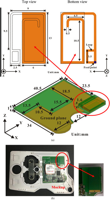
Figure 1 displays the geometry and photograph of the proposed compact tag antenna for UHF active RFID system. This tag antenna with the size of 13 × 9 × 1.6 mm3 is printed on an FR4 substrate (ε r = 4.4, loss tangent = 0.0245) and attached on the top-right main board with the other circuit for active RFID system. The proposed spiral monopole is arranged at the back of the tag antenna and connected with an L-shaped plate along the section DF (i.e. the bottom line of the tag antenna). Additionally as shown in Fig. 1(b), the white plastic mock-up where the proposed tag antenna is embedded has a relative permittivity of 3.0 and loss tangent of 0.02. A 50-Ω mini coaxial line is utilized to connect at the feeding point of the spiral driven monopole and the system grounding point (point G). The driven spiral strip is first arranged as a quarter-wavelength monopole to generate the fundamental resonant mode at approximately 925 MHz. Then, to enhance the impedance bandwidth of the operating band, a closed-loop strip is utilized to reduce the input impedance of the antenna similar to the feeding designs in [Reference Lu and Zheng10, Reference Lu and Siao11]. Moreover, an L-shaped metal plate is introduced to enhance the antenna efficiency of this proposed compact tag antenna. The electromagnetic simulator HFSS based on the finite-element method [14] has been applied for the proposed tag antenna design. The design parameter values obtained by the above strategy are shown in Fig. 1.
Configurations of the proposed compact UHF tag antenna for an active RFID system. (a) Geometry. (b) Photograph.

III. RESULTS AND DISCUSSIONS
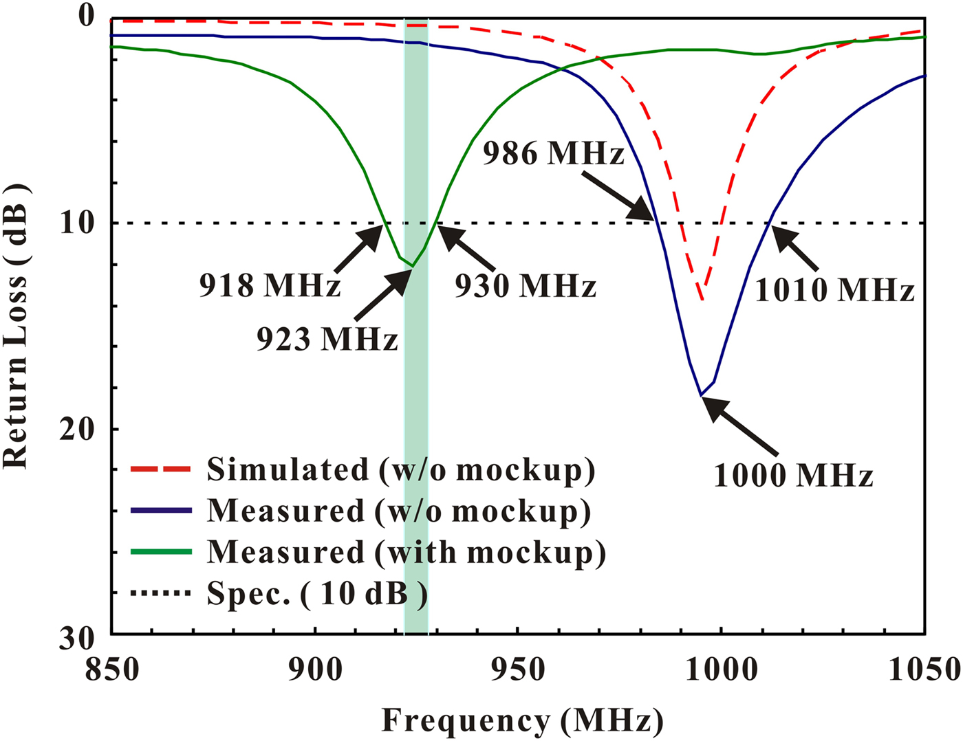
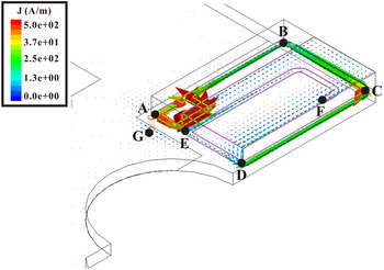
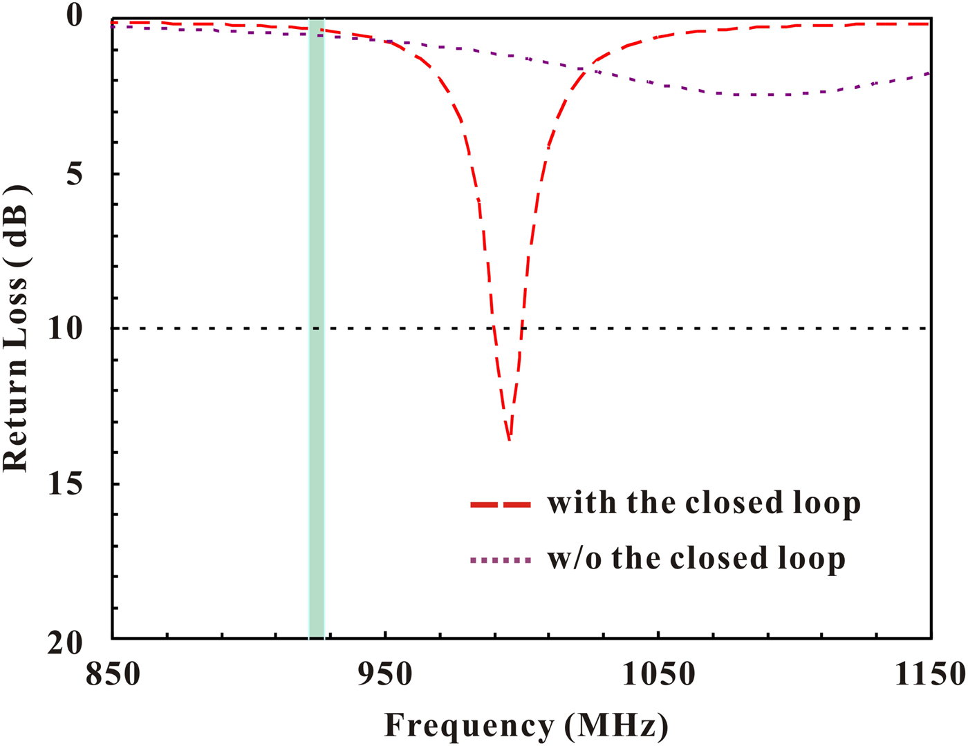
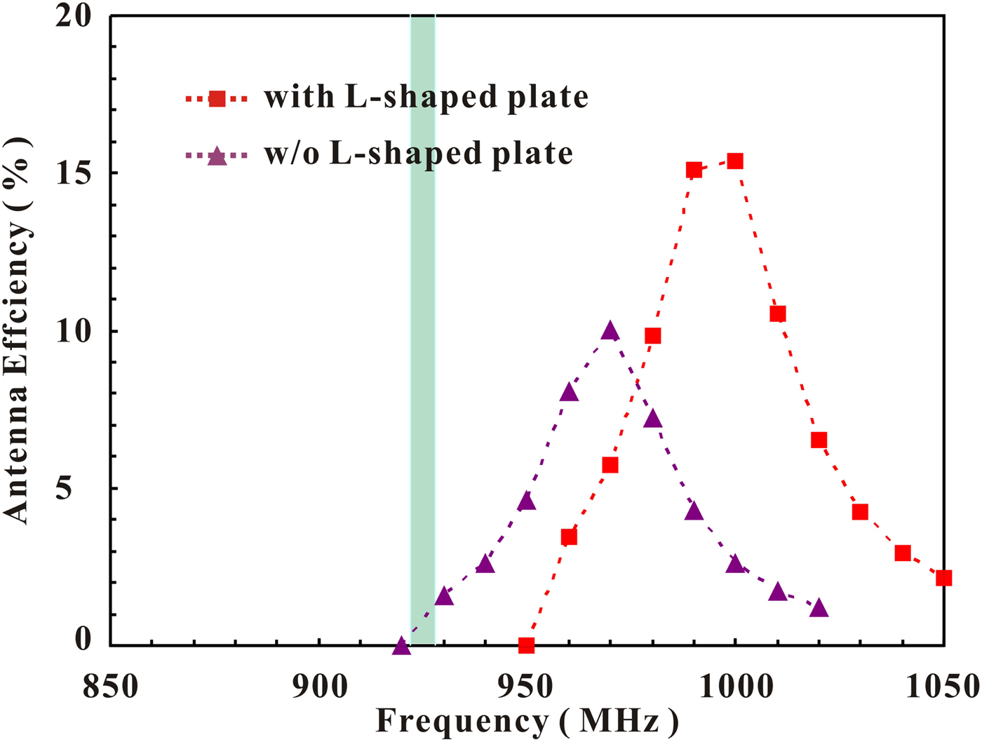
Figure 2 illustrates the related simulated and experimental results of the return loss for the proposed tag antenna with or without the mock-up. From the experimental results for the tag antenna embedded into the mock-up, the measured bandwidth (RL ≧ 10 dB) can be more than 12 MHz (918–930 MHz) to reach Taiwan UHF band (922–928 MHz). Since the dielectric constant and loss tangent of FR4 substrate fluctuate with operating frequency [Reference Namba15, Reference Djordjevic, Biljic, Likar-Smiljanic and Sarkar16], the measured resonant frequency and input impedance for the proposed antenna slightly differ from the simulated results obtained at some substrate parameter settings such as a relative permittivity of 4.3 and a loss tangent of 0.02 across the operating bands. Additionally, the proposed tag antenna is embedded into the plastic mock-up with the relative permittivity of 3.0 and loss tangent of 0.02 [Reference Chen and Wong17] to explain why the measured result for the operating band is decreased and less than that of the proposed antenna without the mock-up. Moreover, Table 1 lists the related results for comparison, indicating a satisfactory correlation for the proposed compact tag antenna operating at the UHF bands for the RFID system. Since the overall antenna dimensions are only 13 × 9 mm2, the proposed tag antenna can be operated with a size that is 89% smaller than that of the smallest tag antenna reported in [Reference Bae, Lee, Chang, Kwon and Yoon4]. Then, to fully comprehend the excitation of UHF band, Fig. 3 illustrates the surface current distribution along the path (A→B→C→D→E→F) of the resonant mode at 1000 MHz for the proposed tag antenna without the mock-up. The surface current length is about 59 mm and correspondingly equal to approximate 0.2 wavelength of the operating mode. Due to the loading effect from the parallel connection with the proposed L-shaped plate, the resonant length is less than the quarter-wave length of a regular monopole antenna. To achieve the desired impedance match, in this study, the closed loop plays an important role. Figure 4 summarizes the results of the simulated return loss for the proposed compact tag antenna with the closed loop or not. Similar to the feeding designs in [Reference Lu and Zheng10, Reference Lu and Siao11], that is, the input resistance decreases, it is clearly seen that the input match becomes better as the closed loop is added in the input port of the tag antenna. Then, to improve the antenna efficiency of the compact tag antenna, the L-shaped metal plate is arranged above the spiral monopole strip to enlarge the electrical size of the monopole antenna. The related simulated results are shown in Fig. 5. It is found that the antenna efficiency increases from 10 to 15%, that is, close to the enhancement of 50%.
Simulated and measured return loss against frequency for the proposed compact UHF tag antenna with mock-up or not.

Simulated surface current distribution on the major metal pattern of the proposed printed monopole antenna.

Simulated return loss against frequency for the proposed compact tag antenna with the closed loop or not.

Simulated antenna efficiency against frequency for the proposed compact tag antenna with the L-shaped plate or not.

Antenna dimensions and performance of typical UHF tag antennas in recent articles.

H and W stand for the height and width of the antenna dimensions.
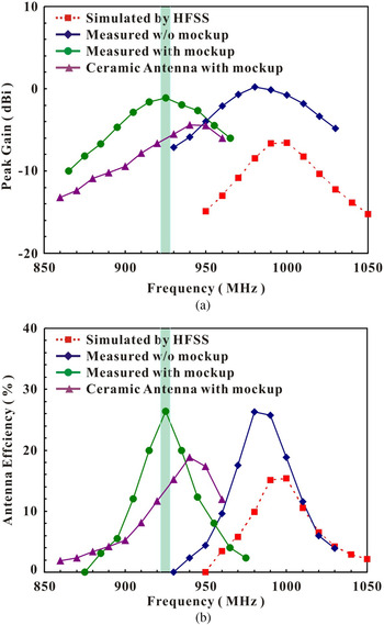
Figure 6 presents the simulated and measured antenna gain and efficiency (mismatching loss included, [Reference Huang and Boyle18]) for the proposed compact tag antenna and the reference ceramic antenna. The simulation results are summarized in this figure for comparison with the measured ones. For frequencies over the lower band, the measured peak gain and antenna efficiency are approximately −1.1 dBi and 27% for Taiwan UHF band, respectively.
Measured and simulated peak gain and antenna efficiency for the proposed compact monopole antenna and the reference ceramic antenna. (a) Peak gain. (b) Antenna efficiency.

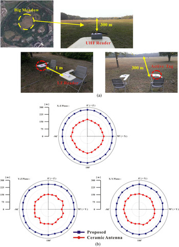
To measure the tag performance and maximum distance between the reader and the proposed tag antenna, the measurement system is set up and arranged in a big meadow with the radius of more than 300 m in the park, as shown in Fig. 7(a). The measuring system provides a variable transmitted power with a cable loss calibration. A reader with an output power of EIRP 1 W is connected to a monopole antenna with a peak gain of 2 dBi. Then, to determine the angular sensitivity toward the radiating wave from the reader antenna, the tag is rotated in intervals of 15o from 0o to 360o in the X–Z, X–Y, and Y–Z planes, as displayed in Fig. 7(b). The radiation patterns in all planes are observed with the maximum reading distance of 250 m, larger than 170 m for the reference ceramic antenna.
Tag performance measurement setup and reading range pattern for the proposed tag and the reference ceramic antenna at 925 MHz band. (a) Practical measurement setup. (b) Measured reading range pattern.

IV. CONCLUSION
A novel compact design of planar tag antenna for the UHF RFID system has been proposed. By introducing a closed-loop strip connecting at the input port of the spiral monopole antenna with the overall antenna size of only 13 × 9 × 1.6 mm3, the measured impedance bandwidth of 12 MHz can be more than the required bandwidth of 6 MHz for the Taiwan UHF (922–928 MHz) RFID system. The measured peak gain and antenna efficiency are approximately −1.1 dBi and 27% for Taiwan UHF band. Meanwhile, the measured reading distance can approach 250 m. Good tag sensitivity is obtained across the desired frequency band.
ACKNOWLEDGEMENTS
The authors would like to thank the Ministry of Science and Technology (MOST) of the Republic of China, Taiwan for financially supporting this research under Contract No. NSC101-2622-E-022-003-CC3.
 Jui-Han Lu has received the Ph.D. degree in Electrical Engineering from National Sun Yat-sen University, Kaohsiung, Taiwan in 1997. In 2001, for his published SCI papers highly cited, he received the Institute for Scientific Information (ISI) Citation Classic Award for “Honoring Excellence in Taiwanese Research” from ISI and the National Science Council of Taiwan. In 2003, he became a Full Professor and was elected as Ten Outstanding Young Persons in Taiwan in 2005 for his contributions in antenna researches and academic-industry cooperation. From 2007 to 2010, Professor Lu served as Dean of the College of Ocean Engineering at National Kaohsiung Marine University. In 2013, with contributions in EM Theory teaching and Mobile Antenna researches, he received MOE (Ministry of Education) Outstanding Teaching and Research Award. Professor Lu presently serves as Chair of IEEE AP-S Tainan Chapter (2013–2014) and is the Awards Committee Chair of 2013 NST (National Symposium on Telecommunications in Taiwan), 2014 ISAP (International Symposium on Antennas and Propagation) and 2016 IEEE 5th Asia-Pacific Conference on Antennas and Propagation. He is a life member of IAET (Institute of Antenna Engineers of Taiwan) and a Senior Member of the IEEE.
 Zi-Hao Liou has received the B.S. degree in Electronic Communication Engineering from National Kaohsiung Marine University, Kaohsiung, Taiwan in 2014. He is currently working toward the M.S. degree at National Kaohsiung University of Applied Sciences, Kaohsiung, Taiwan. His current research interests include antenna design and microwave circuit.