I. INTRODUCTION
Titanium dioxide (TiO2) has long been paid attention to because of its potential for many important applications such as catalysts, photocatalysts, sensors, and light-switchable amphiphilic films.Reference Henrich1–Reference Linsebigler, Lu and Yates6 The physical and chemical properties of TiO2 are strongly affected by the existence of atomic defects such as oxygen vacancies, hydroxyls, and Ti interstitials in its crystal structure.Reference Henrich1–Reference Aono and Hasiguti23 Furthermore, controlling the position of atomic defects in the structure is critical in manipulating the properties of TiO2.
The creation of atomic defects on the TiO2 surface has been achieved by annealing,Reference Henrich1–Reference Linsebigler, Lu and Yates6, Reference Henrich, Dresselhaus and Zeiger24 electron-/photo-stimulated desorption,Reference Henrich1, Reference Knotek and Feibelman25 and reactions with hydrogen sources (atomic hydrogen or water).Reference Pang, Lindsay and Thornton3–Reference Henderson5, Reference Wendt, Schaub, Matthiesen, Vestergaard, Wahlstrom, Rasmussen, Thostrup, Molina, Laegsgaard, Stensgaard, Hammer and Besenbacher16, Reference Suzuki, Fukui, Onishi and Iwasawa26–Reference Kajita, Minato, Kato, Kawai and Nakayama28 These techniques are able to control the atomic defects only at the macroscale. A scanning tunneling microscope (STM) has been used for inducing atomic scale diffusionReference Diebold2, Reference Cui, Wang, Wang, Huang, Zhao, Yang and Hou29 and desorptionReference Wendt, Sprunger, Lira, Madsen, Li, Hansen, Matthiesen, Blekinge-Rasmussen, Laegsgaard, Hammer and Besenbacher14, Reference Minato, Sainoo, Kim, Kato, Aika, Kawai, Zhao, Petek, Huang, He, Wang, Wang, Zhao, Yang and Hou22, Reference Suzuki, Fukui, Onishi and Iwasawa26, Reference Bikondoa, Pang, Ithnin, Muryn, Onishi and Thornton27, Reference Acharya, Ciobanu, Camillone and Sutter30 of the defects. However, the creation of oxygen vacancies via STM, the most typical defect on TiO2 at the atomic scale, has not been achieved so far.
Here, we report the creation of single oxygen vacancies at desired sites on the TiO2 surface using STM. In addition, based on the experimental data, we discuss the manipulation of atomic defects on the TiO2 surface using STM.
II. EXPERIMENTAL
All experiments were performed in ultrahigh vacuum at 78 K under conditions that permitted unequivocal identification of each defect. STM experiments were performed using a Low temperature scanning tunneling microscope/scanning tunneling spectroscopy (LT-STM/STS) system (Omicron GmbH, Erlangen, Germany) consisting of two chambers separated by a gate valve. TiO2(110) single crystals (Furuuchi Chem. Co. Ltd., Tsukuba, Japan) were cleaned in the preparation chamber with base pressure of 8 × 10⁻⁸ Pa by cycles of Ar+ sputtering (3 – 5 keV) and annealing at 900–1000 K. After the surface preparation, the sample was transferred immediately to the STM chamber with the base pressure of 1 × 10⁻⁹ Pa to obtain TiO2(110) surface with Ob vacancies before their reacting with the residual H2O molecules to form OH.Reference Wendt, Schaub, Matthiesen, Vestergaard, Wahlstrom, Rasmussen, Thostrup, Molina, Laegsgaard, Stensgaard, Hammer and Besenbacher16,Reference Minato, Sainoo, Kim, Kato, Aika, Kawai, Zhao, Petek, Huang, He, Wang, Wang, Zhao, Yang and Hou22 STM images were acquired in the constant current mode with a chemically etched W tip.
III. RESULTS AND DISCUSSION
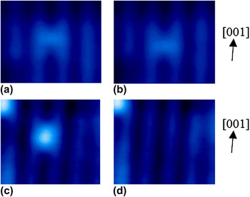
Figure 1 shows a typical example of oxygen vacancy diffusion and desorption of hydroxyl (Ob–H) on a bridging oxygen (Ob) row on TiO2(110) by applying a pulse of positive sample bias (V s). The bright spot on the dark line at the center of the STM image in Fig. 1(a) is a vacancy of a bridging oxygen (Ovac).Reference Wendt, Schaub, Matthiesen, Vestergaard, Wahlstrom, Rasmussen, Thostrup, Molina, Laegsgaard, Stensgaard, Hammer and Besenbacher16, Reference Minato, Sainoo, Kim, Kato, Aika, Kawai, Zhao, Petek, Huang, He, Wang, Wang, Zhao, Yang and Hou22, Reference Suzuki, Fukui, Onishi and Iwasawa26, Reference Bikondoa, Pang, Ithnin, Muryn, Onishi and Thornton27 After applying a V s = +3.5 V pulse for 1 s with the feedback loop turned off to maintain the tip Z position, the position of the Ovac was changed to a lower position (0.30 nm) along the [001] direction as shown in Fig. 1(b). In contrast, after applying a V s = +1.7 V for 1 s on (Ob–H) [the bright spot at the center of the STM image in Fig. 1(c)], H was removed from the TiO2(110) surface [Fig. 1(d)]. These reactions agree with previous reports of defect diffusion and desorption on TiO2(110) using STM.Reference Diebold2, Reference Wendt, Schaub, Matthiesen, Vestergaard, Wahlstrom, Rasmussen, Thostrup, Molina, Laegsgaard, Stensgaard, Hammer and Besenbacher16, Reference Minato, Sainoo, Kim, Kato, Aika, Kawai, Zhao, Petek, Huang, He, Wang, Wang, Zhao, Yang and Hou22, Reference Suzuki, Fukui, Onishi and Iwasawa26, Reference Bikondoa, Pang, Ithnin, Muryn, Onishi and Thornton27, Reference Cui, Wang, Wang, Huang, Zhao, Yang and Hou29 STM imaging at positive sample bias reveals that the Ovac and Ob–H show similar contrast; however, the distinction between Ovac and Ob–H is possible via their reaction to the pulse injection of positive sample bias.Reference Wendt, Schaub, Matthiesen, Vestergaard, Wahlstrom, Rasmussen, Thostrup, Molina, Laegsgaard, Stensgaard, Hammer and Besenbacher16, Reference Minato, Sainoo, Kim, Kato, Aika, Kawai, Zhao, Petek, Huang, He, Wang, Wang, Zhao, Yang and Hou22, Reference Suzuki, Fukui, Onishi and Iwasawa26, Reference Bikondoa, Pang, Ithnin, Muryn, Onishi and Thornton27
Constant current STM images (V s = +1.5 V, I t = 0.3 nA, T s = 78 K, 3.5 × 3.0 nm) of TiO2(110) before (a and c) and after (b and d) applying a pulse on Ovac (a and b) and Ob–H (c and d). The applied pulses were V s = +3.5 and +1.7 V for 1 s. to Ovac and Ob–H, respectively, with the feedback loop turned off.

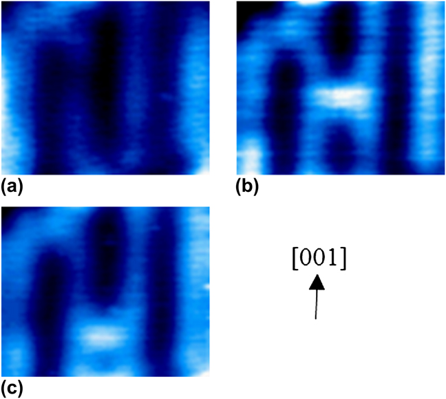
Figure 2 shows the reaction to a pulse injection of negative sample bias at Ob. A −2.0 V pulse was applied on Ob [center of Fig. 2(a)] for 1 s with the feedback loop turned off. After the pulse injection, a bright spot appeared at the injection site [Fig. 2(b)]. The apparent height difference from the five-coordinated Ti (Ti5c) of the visible species (0.2 nm) is well matched with one Ovac.on TiO2(110) (0.2 nm). To confirm the assignment of the visible species, a pulse of positive sample bias (V s = +4.0 V for 1 s with feedback loop off) was applied it. After applying the pulse, the visible species moved toward a lower site along the [001] direction [Fig. 2(c)]. This confirms that the visible species is single Ovac. This is the first demonstration of the creation of a single oxygen vacancy at a desired site.
Constant current STM images of TiO2(110) before (a) and after (b) pulse injection on Ob. (c) A constant current STM image obtained after applying a pulse on the appeared species at the center of STM image in (b). All STM images were obtained by V s = +1.5 V, I t = 0.3 nA, T s = 78 K, 3.5 × 2.9 nm. The applied pulses were V s = −2.0 and +4.0 V for 1 s to Ob and the appeared species, respectively, with the feedback loop turned off.

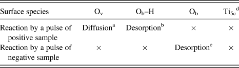
From the experimental results, we infer that diffusion, desorption, and creation of defects on TiO2(110) are successfully induced in a controlled manner at the atomic scale. However, the mechanism of this STM-induced reaction is unclear. To analyze the reaction mechanism, we investigated the reaction against positive (V s = +5.0 V for 1 s) and negative (V s = −2.0 V for 1 s) pulses on Ovac, Ob–H, Ob, and Ti5c. As summarized in Table I, Ovac and Ob-H react when a pulse of positive sample bias (electron injection) is applied. At the Ovac sites, a voltage pulse is applied to the positively charged Ti ions under Ovac. H on Ob is positively charged. Therefore, the positively charged ions react only when a pulse of positive sample bias is applied. In contrast, Ob, which has a negative charge, reacts only with the pulse of negative sample bias (hole injection). Based on these results, we propose that the STM-induced reactions of atomic defects on TiO2(110) strongly correlate with the electric field between the tip and sample.
Reactions of the atomic defects on TiO2(110) against applying pulse by an STM tip.

b Refs. Reference Wendt, Sprunger, Lira, Madsen, Li, Hansen, Matthiesen, Blekinge-Rasmussen, Laegsgaard, Hammer and Besenbacher14, Reference Minato, Sainoo, Kim, Kato, Aika, Kawai, Zhao, Petek, Huang, He, Wang, Wang, Zhao, Yang and Hou22, Reference Suzuki, Fukui, Onishi and Iwasawa26, Reference Bikondoa, Pang, Ithnin, Muryn, Onishi and Thornton27, and Reference Acharya, Ciobanu, Camillone and Sutter30.
c If hydrogen is adsorbed on the STM tip, the hydrogen moves from the tip to Ob.Reference Acharya, Ciobanu, Camillone and Sutter30 Ti5c did not show any reaction with the pulse application. This may originate from the high coordination with the surrounding oxygen atoms.
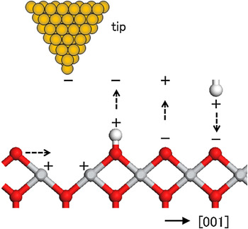
The reactions induced by the STM pulses are schematically shown in Fig. 3. By applying a positive sample bias at a Ovac site, the neighboring Ob, which has a negative charge (formal charge −2),Reference Henrich1, Reference Diebold2 is attracted to the Ovac site under the tip. The movement of Ob to the Ovac site produces diffusion of Ovac. Therefore, the diffusion of Ovac is observed when a pulse of positive sample bias is applied. Conversely, when a pulse of positive sample bias is applied at an Ob–H site, the negative charge on the STM tip attracts H, which has a positive charge on Ob.Reference Henrich1–Reference Linsebigler, Lu and Yates6 Previous photo-electron spectroscopy and density functional theory studies showed there is no occupied electronic state corresponding to a resonant level with the energy of injected electrons.Reference Henrich1–Reference Linsebigler, Lu and Yates6 Hence, the desorption of H by a pulse of positive sample bias is considered to be induced by the electric field between the STM tip and the sample surface. As reported by Acharya et al.,Reference Acharya, Ciobanu, Camillone and Sutter30 the desorbed H is attached onto the STM tip. By applying a pulse of negative sample bias, the H on the STM tip returns to the Ob site.Reference Acharya, Ciobanu, Camillone and Sutter30 Similarly to the diffusion of Ovac and desorption of H, the creation of Ovac (desorption of Ob) are induced by the electric field between the STM tip and the sample surface. Because Ob has a negative charge, it is attracted to the STM tip that has a positive charge. As discussed above, we propose that the reactions of the atomic defects on TiO2(110) are induced by the electronic field between the STM tip and the sample surface.
The above discussion does not deny the effect of electronic/vibrational state excitation induced by tunneling electrons on the reaction. From the polarity dependence of the tip-induced reactions (Table I) and the electronic structure reported in the literature,Reference Henrich1–Reference Linsebigler, Lu and Yates6 we believe that the electronic field plays an important role in these reactions. The detailed mechanism of electron excitation will be discussed in a future article.Reference Minato, Kajita, Pang, Asao, Yamamoto, Nakayama, Kawai and Kim31
A schematic image of reactions of atomic defects on TiO2(110) by a STM tip. Gray, red, and white balls are Ti, O, and H atoms, respectively.

IV. CONCLUSION
In conclusion, we have demonstrated that the creation of single Ovac at desired sites is possible by applying a bias pulse by the STM tip. The alignment control of the atomic defects is possible with the combination of diffusion and desorption of the atomic defects. We propose that these reactions are strongly related to the electric field between the STM tip and the sample surface. Applications of this technique can apparently modify the surface and, thus, alter the physical and chemical properties of TiO2 and related metal oxide materials.
ACKNOWLEDGMENTS
This work was supported by Grant No. 21750002 from Ministry of Education, Culture, Sports, Science and Technology of Japan and the Japan Science Society and Sasakawa Foundation (the Japan Science Society) and Grant for Exploratory Research for Young Scientists (Tohoku University).