NOMENCLATURE
- ECU
-
Electronic Control Unit
- EGT
-
Exhaust Gas Temperature
- FAA
-
Federal Aviation Administration
- FMEA
-
Failure Mode and Event Analysis
- FTA
-
Fault Tree Analysis
- HAZOP
-
Hazard and Operability
- RPM
-
Revolutions Per Minute
- SSL
-
Secure Sockets Layer
- XML
-
eXtensive Markup Language
Symbols
- m
-
times of execution
- n
-
number of states
- pij
-
transition probability
- R
-
reliability for single execution
- E[R]
-
overall reliability of a system
- si
-
state
- t
-
time
- θ
-
failure rate
- σ
-
standard deviation
1.0 INTRODUCTION
Internet applications are gaining increasing popularity during the last decades and they are used in many aspects of everyday life, such as web banking, online shopping and mail exchange. Internet technology is available worldwide at low cost. The aim of this project is to introduce a software application which will enable safe, secure and reliable remote operation and monitoring of an aero gas turbine situated in a test facility, through the Internet. The end user will be able to perform various tests on the gas turbine from anywhere, without any local installation prerequisites at the user's computer or any other Internet access device.
1.1 Relevant applications and problem definition
In the aviation field, there are applications based on Internet technology that allow the management of the technical operations of an airline fleet. Operations such as quality monitoring, reliability trends and status reports can be obtained via web services(1). Manage/m, a Lufthansa Technik developed Maintenance Repair and Overhaul (MRO) websuite can provide troubleshooting support by using the data of the aircraft and its engines condition from on- board computers, even when the aircraft is airborne.
1.1.1 Industrial applications
In the industrial sector, similar applications based on Internet technology can be found in power-plant systems management. An example of that is the Siemens SPPA- T3000 Control System for power plant management and control. As presented by Siemens, this system provides real-time data at any place and any time, single software system imaging and simplification of the system architecture, rendering it easy to learn and use(2). According to a research study from Karlsruhe University Germany, supervised by Siemens and available in the public domain, SPPA- 3000 is based on Java and eXtensive Markup Language (XML) and the application server can be accessed by any web browser. The web page of the application server consists of several Java applets.
1.1.2 Academic applications
Similar Internet applications are very common in the Academic Field as useful tools for the remote creation of simulation models and even real-time conduction of control experiments with Internet operation of mechanical or electronic devices. An example is the NCSLab, developed by Glammorgan University. It is a Control Engineering experiment platform which consists of 6-tier architecture, based on MATLAB- Simulink. Several other control engineering web-based platforms have been developed around the world such as a web- based laboratory for control experiments on a coupled tank apparatus by Ko et al. (2001)(Reference Ko, Chen, Jianping, Zhuang and Chen3) and WebLab Development for Kyatera Network by Okajima et al. (2006)(Reference Okajima, Ledel, Fragnito and Rocha4). The last two applications use downloaded java applets on the client side in order to operate remotely.
1.1.3 TURBOMATCH WebEngine
The TURBOMATCH WebEngine is an Internet application developed by Cranfield University, for the creation of gas-turbine performance-simulation models(Reference Apostolidis, Sampath, Laskaridis and Singh5). It utilises TURBOMATCH in the server side, a powerful gas-turbine performance-simulation tool developed by Cranfield University as well. The WebEngine offers ease of use with no local installations required. It is based on client–server architecture, with TURBOMATCH as the core solver behind the Graphical User Interface (GUI). TURBOMATCH is a software-based gas-turbine performance simulation tool developed by the Propulsion Engineering Centre in Cranfield University. It was developed in a modular zero-dimensional structure, meaning that every existing or conceptual engine can be thermodynamically described by a sequence of pre-programmed components that represent the actual intakes, compressors, combustors, turbines, nozzles, ducts, bleed valves and mixers. Every component unit, referred to as Brick, is in reality a routine capable of calculating the thermodynamic process that takes place through the equivalent engine part. Certain inputs are required for every Brick, such as rotational speed, isentropic efficiency, pressure ratio or pressure losses(Reference Apostolidis, Sampath, Laskaridis and Singh5).
1.2 Significance
This project introduces a novel application for real-time remote operation and monitoring of aero gas turbines through the Internet, with standard browsers as thin clients and without prerequisites of additional installed software components at the user's end. It demonstrates how the underlying physical risks, Internet security and network performance can be weighted and combined accordingly to provide a reliable tool. The outcome is a flexible system that can be integrated with Internet gas turbine performance simulation applications, providing a powerful experimental and testing platform.
1.3 Olympus micro gas turbine
The gas turbine used for the project is an Olympus micro gas turbine manufactured by AMT Netherlands (Fig. 1), used in radio-controlled aircraft, gliders, remote heat/power generators or auxiliary power units(6). It is a miniature single-spool turbojet gas turbine with an overall length of 270 mm, maximum diameter of 130 mm and maximum thrust of 190 N at maximum Revolutions Per Minute (RPM) (110,000). The single-stage centrifugal compressor delivers a pressure ratio of 4:1 and handles a maximum value of mass flow 400 gr/sec(7). It is controlled by a closed loop control Electronic Control Unit (ECU).
Olympus gas turbine front view and main dimensions(7).

2.0 METHODOLOGY
The development of a software system is described by the software process, which is a group of activities leading to the production of a software product(Reference Sommerville8). The software process can be described by appropriate models. The process herein followed the Spiral Model (Fig. 2), introduced by Boehm (1988)(Reference Boehm9) in order to overcome the difficulties imposed by the techniques that existed up to then, such as the waterfall model, the evolutionary model and the transform model. The spiral differs from the other software development models mainly in the identification and consideration of risk(Reference Sommerville8).
The spiral model(Reference Boehm9).

For this application, there were six phases (rounds) considered:
-
• Round 0: Feasibility study and System Requirements definition
-
• Round 1: Local interfacing of the gas turbine
-
• Round 2: Design of operation-control software
-
• Round 3: Implementation of additional performance and safety features
-
• Round 4: Internet application design
-
• Round 5: Acceptance validation
2.1 Definition of the application and validation
The requirements elicitation process included use-case scenarios, following the requirement elicitation template of Dependable Product Lines, proposed by Gallina et al. (2007)(Reference Gallina, Guelfi, Sawyer, Paech and Heymans10), which includes among others, fault assumptions and risk analysis. The System Requirements were classified in different modes of operation and expressed in structured natural language, in order to avoid the ambiguities of natural language(Reference Broy, Breitman and Cavalcanti11).
Validation took place after the completion of each individual development phase. The criteria for evaluation were set in accordance with the RTCA/DO-178 document guidelines (Software Considerations in Airborne Systems and Equipment Certification), used by software developers in avionics in order to obtain Federal Aviation Administration (FAA) approval(Reference Hayhurst, Veerhusen, Chilenski and Rierson12). The DO-178 document includes guidelines for the software lifecycle, the planning and development process, verification, configuration management and quality assurance. An important topic within the document is the definition of criticality levels of software, determined according to the extent of the damage caused in the case of a failure, ranging from E (no effect) to A (catastrophic)(Reference Hilderman and Baghi13) (Fig. 3). For this project, criticality level C was considered. Criticality level C implies major damage to components – in this case the gas turbine – and this was determined by applying an analytic Event Tree Analysis (ETA) to investigate the potential outcomes of a situation where the remote operation control capability of the engine was inadequate or totally lost. The criticality level determines the depth of the validation tests required for certification;(Reference Hayhurst, Veerhusen, Chilenski and Rierson12) hence, the amount and type of the test cases applied are directly affected by this. Criticality level C requires testing of the software to ensure total statement coverage.
Criticality levels according to DO-178B(Reference Hilderman and Baghi13).

The final validation included two main tasks:
-
• Functionality validation,
-
• Probabilistic reliability analysis.
Functionality validation was obtained with the use of a formal validation method (Model Checking) to define all the possible test cases. Model Checking is commonly applied in critical software systems. In contrast to simulation, formal verification methods do not rely upon the dynamic response of the system, but perform static analysis on a formal mathematical representation of the system, in order to check it for correctness with respect to a given specification. Model Checking has been gaining popularity in aerospace systems design and verifications over the last few years(Reference Ameur, Boniol and Wiels14). It is a powerful approach for the formal verification and validation of software. It automatically provides complete proofs of correctness, or explains, via counter-examples, why a system is not correct(Reference Berard, Bidoit, Finkel, Laroussinie, Petit, Petrucci and Schnoebelen15).
Probabilistic reliability analysis relied on Markov equations, which is an approach based on a state diagram and applicable in risk assessment of power systems(Reference Li16). Having assumed reliabilities of individual components to be known, Gokhale et al. (2002)(Reference Gokhale and Trivedi17) stated that the overall reliability of the examined system for single execution is given by:
 $$\begin{equation}
R = \mathop \prod \limits_{i = 1}^n R_i^{{X_{1,i}}}
\end{equation}$$
The number of visits to each component is a random variable, implying that reliability also is a random variable. With the use of a Taylor series, they concluded that the expected reliability of the system is given by:
 $$\begin{equation}
E\left[ R \right] = \left[ {\mathop \prod \limits_{i = 1}^{n - 1} \left( {R_i^{{m_{1,i}}} + \frac{1}{2}\left( {R_i^{{m_{1,i}}}} \right){{\left( {{\rm{log}}{R_i}} \right)}^2}\sigma _{1,i}^2} \right)} \right]{R_n}
\end{equation}$$
By ignoring the second-order architectural effects, Equation (2) can be reduced to the following expression:
 $$\begin{equation}
E\left[ R \right] \approx \mathop \prod \limits_{i = 1}^{n - 1} R_i^{m1,i}{R_n}
\end{equation}$$
From the results of the study by Gokhale et al. (2002)(Reference Gokhale and Trivedi17), it was observed that the difference of reliability estimation was of 3rd-decimal magnitude. Thus, for the preliminary reliability analysis of the designed application, Equation (3) was considered to be adequate and hence applied. When the failure rate is constant, the reliability function can be expressed exponentially in terms of time t and failure rate θ(Reference Clarke, Power, Babich and King18):
 $$\begin{equation}
R\left( t \right) = {e^{ - \theta t}}
\end{equation}$$
2.2 Risk assessment
A variety of risk assessment methods were implemented, according to the requirements of each phase of development of the application. Risk assessment in the Spiral model development is evident at the initiation of each round. Fault Tree Analysis(19) and Hazard and Operability (HAZOP)(20) were applied at the early stages of the development. Fault Tree Analysis (FTA) (Fig. 4) is often found in power plant, aerospace, chemical and nuclear systems (FTA)(Reference Fullwood21,Reference Hignett22) . This method is based on the identification of a top undesirable event that corresponds to a particular failure mode and consists of the individual events that contribute to the top event. FTA is a qualitative method in its nature but it can also provide a quantitative aspect as well(Reference Stamatelatos23).
A simplified FTA tree(Reference Stamatelatos23).

HAZOP analysis is a method mainly used by the chemical industry(Reference Fullwood21) and it deals with the identification of deviation from the design intent, also investigating the causes and assessing their consequences(20). It was used as an additional tool to explicitly address the risks identified by FTA.
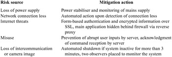
In the first phase of the development (round 0), a general risk assessment was conducted with FTA. Two major undesirable situations were considered: Total loss of command of the gas turbine and sending erroneous command orders. All the individual events that could contribute to the major undesirable situations were identified and Boolean algebra was applied in order to determine the most likely combinations to occur. The major risks that were identified and the mitigation actions are listed in Table 1.
Mitigation of major risks

In the subsequent phases, Failure Mode and Effect Analysis (FMEA) was applied for physical and procedural risk assessment. FMEA is a method for the analysis of a system in order to identify the potential failure modes, their causes and any effects on the system performance(24). FMEA is extremely efficient when it is applied to the analysis of elements that cause a failure of the entire system or of a major function of the system. It can be used alone or as a systematic inductive method of analysis, to complement other approaches, especially deductive ones, such as FTA. It is found in nuclear, chemical(Reference Fullwood21) and other applications.
In all the following phases, the risks were classified in two categories: physical and procedural. The former were those risks associated with the condition and operation of mechanical components, instrumentation, computers and software modules. The latter were the risks associated with the planning, the equipment acquisition and the software development.
2.3 Performance monitoring
The performance of the gas turbine during remote operation is constantly monitored by a dedicated module. This module observes the critical performance parameters (currently Exhaust Gas Temperature (EGT) and RPM) and generates warning messages or executes automatic safety actions if necessary. The assessment of the critical parameters is based on engine control systems theory.
Control systems apply alarm rules in order to detect values above certain limits during the engine operation. There are four unusual patterns of data points:
-
• The instability pattern, where points are present outside the control limits,
-
• The mixture pattern, characterised by the absence of points near the centreline,
-
• The stratification pattern, with the absence of points near the control limits and
-
• The trend pattern, where an upward or downward trend is present.
The most noticeable for the present study is the instability pattern, which indicates the existence of data points outside the control limits. The rules which are most widely applied for the classification are the Western Electric rules (Fig. 5). The control band is divided into three zones where zone A is the area enclosed within two and three standard deviations (σ) of the parameter, zone B, which stays between 1σ and 2σ and C, between ±1σ. A guideline for the alarm generation is: any point beyond zone A, two out of three consecutive points in zone A, three out of five consecutive points in zone B and eight consecutive points on the same side of the centreline(Reference Jaw and Mattingly25).
Western electric rules(Reference Jaw and Mattingly25).

2.4 Security over the internet
The web application was configured in a modular manner. The lowest tiers of the architecture are not exposed directly to the Internet, as they remain situated behind the firewall of the University. An Apache Hyper Text Transfer Protocol (HTTP) server has been configured as a Reverse Proxy(26) and installed as the front end to the web applications. Virtual hosts have been designed to map the requests and redirect to the web applications. The virtual servers can be installed in the De-Militarised Zone (DMZ) of the IT Department of the University and accessed through the Virtual Private Network (VPN) tunnel. The web applications can be deployed in the local server behind the firewall. The application implements the Secure Socket Layer (SSL) protocol for data exchange. This is a cryptographic protocol that provides encryption of the data flowing between the end parts. Additionally, the back end of the web application (local server), implements a form-based user authentication(Reference Heffelfinger27).
3.0 APPLICATION STRUCTURE AND FUNCTIONALITY
The application was designed in a way to satisfy flexibility in the operation of the gas turbine, but optimised for security and safety. The architectural structure and implementation of the software was accomplished in adherence to an appropriate standard for software quality metrics, such as functionality, reliability, usability, efficiency, maintainability and portability(Reference Sommerville8). It can be accessed by any standard web browser in various operating systems.
3.1 Architectural structure
The application is structured as a client–server model. The requested services can clearly be distinguished and associated with a set of servers and clients who use them. Distributed architecture allows effective use of networked systems with many processors. It is also allows addition and integration of more servers(Reference Sommerville8). This architecture easily allows the inclusion of additional gas turbines in future evolution of the project. Also, changes in any sub-system can be isolated, thus preventing any effect on other components, enhancing the changeability and maintainability of the designed software. The system comprises a multiple layer structure, which is more scalable than simple 2-tier architecture and also reduces network traffic(Reference Sommerville8). The local server that is connected with the engine and the hardware is well hidden behind the reverse proxy and the intermediate firewalls (Fig. 6).
Architectural structure of the internet gas turbine application and arrangement of front and back end servers.

3.2 Functionality
An ergonomic web page has been designed for the remote users (Fig. 7). The hosting website also provides access to a training web page that explains the functionality of each item on the operation control web page.
Engine operation panel web page.

The operation panel page was designed ergonomically with control, indications and warnings placed in three separate columns. The reception of a command on the server side is acknowledged by the illumination of a green indication underneath the corresponding control widget. For the throttle, if a new setting that is greater than 20% from the previous setting is selected, the command will be rejected at the server side and the response will trigger the illumination of a red indication light under the throttle bar. Other main functionality features include the following:
-
• Only one user at a time is allowed with full privileges to operate the engine. Monitoring can be available for administrators.
-
• Updates asynchronously only the fields necessary and not the whole web page. This is achieved by implementation of asynchronous JavaScript XML (AJAX) technology.
-
• If the user's webpage has been inactive for 3 minutes, the system shuts down the gas turbine automatically and resets the application to accept a new user.
-
• If connection is lost, the system shuts down the gas turbine automatically within 7 seconds.
-
• Monitoring of EGT and RPM. If a relative limit exceedance is observed (value higher than 2 × σ), the user is given a caution message and if no action taken within 3 minutes, the system shuts down the gas turbine automatically. If an absolute limit exceedance is observed (manufacturer's upper limits), the user receives a warning message and the system shuts down the gas turbine automatically within 5 seconds,
-
• Monitoring of the mains power supply at the test house where the engine is installed. If any disruption is noticed, the user receives a message and a 3-minute time space is allowed before the system shuts down the gas turbine automatically
3.3 Results of validation
The indications of the Olympus gas turbine were captured from the remote operation control software with high accuracy. The RPM indication was totally matched (100%) throughout the whole throttle range. The EGT was nearly 100% matched, with deviation less 1% (Fig. 8). This deviation was due to higher precision of representation of the numerical values at the remote operation software. The same levels of accuracy were obtained for all other secondary indications of the gas turbine.
Accuracy of capturing EGT value with remote operation control software.

There were a total of 168 test cases derived from the Model Checking tool (NuSMV) that was applied for the final validation process. These cases not only covered a full engine test sequence, but tested every possible function that could be done from the application remotely, as well as all the automated safety features. A dedicated software platform was also created in order to imitate the functionality of the gas turbine and transmit all the possible fault codes in the same form as they are transmitted from the gas turbine ECU. The test platform simulated the performance of the actual engine through field data obtained at various operating conditions, referred to as International Standard Atmosphere Sea Level (ISASL) conditions.
Accomplishment of all the defined test cases confirmed 100% statement coverage of the designed software, which is the minimum requirement for criticality level C according to DO-178(Reference Hayhurst, Veerhusen, Chilenski and Rierson12). Preventively, the test cases were designed to also ensure 100% decision coverage, although this is a requirement for higher criticality levels.
A preliminary estimation of reliability was accomplished by implementation of Equations (1) through (4). The system was represented by a finite absorbing Discrete Time Markov Chain(Reference Trivedi28), constructed by the software and hardware components that form the application (Fig. 9). Initial results showed an expected reliability of around 0.5, due to low reliability of components s14 and s15 during start-up of the application. Introduction of time delay (500 ms) in the starting up sequenced, reducing the number of experienced failures and improved reliability. There were no other significant failures observed during the validation testing period.
Representation of the Internet Gas Turbine application as a Discrete Time Markov Chain (DTMC).

4.0 CONCLUSIONS – FUTURE PERSPECTIVE
The design took into account the main features of operation and safety of a gas turbine, and combined them with Internet security and performance elements to eventually produce a system that operates successfully and reliably. The final result of this work was an application for real-time remote operation and monitoring of aero-gas turbines through the Internet, with standard browsers, without prerequisites of additional installed software components at the user's end.
The new application has provisions and capabilities of expansion and collaboration with other online applications, to form powerful experimental and operation facilities at low cost, as the majority of the software tools used was open source. It also forms a basis that can be used to develop real-time online diagnostic applications that implement different health monitoring techniques. It currently monitors gas path parameters but integration of appropriate instrumentation will allow inclusion of additional diagnostic methods by monitoring vibration or shaft dynamics. An integrated health monitoring solution combined with the relatively low cost of development can have a direct impact on gas turbine reliability and availability, accompanied by a positive effect on the overall economic performance of the aircraft on which the monitored gas turbines may be installed.
The system includes features to ensure physical safety and mitigation of Internet-based risks. The underlying risks were identified throughout the software process and all the major risks were mitigated accordingly. The application has adhered to various quality and safety guidance standards and was validated in accordance to DO-178, as per FAA requirements. The reliability was examined and potential bottlenecks were identified, leading to corrective actions that alleviated observed weaknesses.
The indications of the gas turbine indication system were accurately captured and transferred into the software modules. Finally, the developed software modules have demonstrated sufficient abidance to software quality metrics, as defined by relevant standards.
4.1 Future perspective
The Internet Gas Turbine application includes provision for several expansion and evolution capabilities. This has been obtained by the modular architecture of the software design, which allows modifications of certain modules only, in order to accommodate new features. The use of software patterns and Interface classes enhances the flexibility of the program in terms of inserting additional functionality. Analytic plans for each expected expansion capability have been developed thus providing guidelines for future researchers to easily adapt the existing software. The application is also accompanied by the complete developer's documentation according to relevant standards. The main future capabilities are listed below:
-
• Installation of a variety of instrumentation to enable real time monitoring of more engine parameters on the existing micro gas turbine and allow full automation of operation;
-
• Addition of multiple gas turbines of different types that can be operated independently;
-
• Integration with the TURBOMATCH WebEngine online performance simulation. This will enable instantaneous validation of performance simulation models online;
-
• Collaboration with software modules for real-time diagnostic or trend analysis of the engine; and
-
• Operation of UAV's with the use of standard Internet technology and Wi-Fi transmission
ACKNOWLEDGEMENTS
The completion of this project was accomplished with the support of a team that provided essential guidance throughout the duration of the development. Dr Stuart Barnes set the basis for the software engineering methodology and Dr Mark Stilwell supported the Internet-related part of the work. However, this project could not have been accomplished without the inspiration and motivation from the Head of Propulsion Engineering Centre in Cranfield University, Pr Perikles Pilides.