Introduction
The rapid development of the wireless communication technology is to meet people's demand for high rate and large capacity [Reference Deroba, Schneider, Schuetz and Prather1–Reference Hong, Baek and Ko2]. The multi-beam antenna has the advantages of simple structure, easy implementation, and accurate beam control, which can improve the capacity of the system and achieve a higher signal-to-noise ratio. Therefore, the study of multi-beam antenna becomes more and more prevalent [Reference Molisch, Ratnam, Han, Li, Nguyen and Li3–Reference Jiang, Chen, Zhang, Hong and Xuan4]. The core technology for multi-beam antenna is its beam forming network. There are several methods to design this circuit, such as Blass matrix [Reference Mosca, Bilotti, Toscano and Vegni5]. To avoid complex processing of the signal to realize the power and phase distribution, Butler matrix is more attractive to a lot of researchers [Reference Lian, Ban, Xiao and WU6–Reference Chu, Hong, Zheng, Yang, Xu and Wu14]. Comparing with digital beam forming (DBF) antenna, the circuit of Butler matrix has the advantages of low cost, easy design, and high reliability.
For the traditional Butler matrix, the number of input ports and outputs is in even order, such as 4 × 4 or 8 × 8 networks. It can produce even beams with axis symmetry. With the concept that the selected performance obtained for N × N Butler matrix at f 0, whereas at 2f 0 they show the properties of N/2 × N/2 Butler matrix, a frequency-dependent Butler matrix can smoothly change their properties across an octave frequency band and achieve two and four symmetrically located beams for antenna array [Reference Wincza, Staszek and Gruszczynski7]. With the function of power division and phase shifter together, the filtering 180° hybrid coupler is applied in the design of 2 × 4 filtering Butler matrix, which produces boresight and endfire radiation patterns performance [Reference Shao, Chen, Chu and Lancaster8]. A swap was introduced in a vertically installed planar structure to implement the quadrature coupler due to the location of output ports [Reference Chen, Qamar, Zheng, Long and Ho9]. With this method, a compact wideband 4 × 4 Butler matrix with the operating frequency of 1.8 GHz is designed for four-beam antenna array. A broadband eight-port forward-wave directional coupler with arbitrary coupling level was proposed in [Reference Ting, Hsu and Wu10]. Then a three-layer Butler matrix with multi-input phase shifter was designed for eight-beam antenna array. Different from the Butler matrix with even input ports, tri-beam Butler matrix was proposed and designed in [Reference Luo, Dai, Sun, Yuan and Zhang11–Reference Sun, Dai, Luo, Wang and Mao12]. It can produce one beam pointed at 0° and two axisymmetric beams. Compared with microstrip transmission lines, substrate integrated waveguide (SIW) has better transmission performance when the frequency is high. Therefore, many researchers have made detailed study and analysis of the SIW characteristics, and have done a lot of research on the SIW microwave components [Reference Yu, Hong, Zhang, Xu and Jiang13–Reference Sakr, Dyab and Wu16].
In this paper, Butler matrix with odd number input and output ports is proposed. Based on SIW technology, 3 × 3 Butler matrix with 0° axis beam covering is designed. With three couplers and four phase shifters, the proposed structure can divide the input signal into three parts with the same amplitude and certain phase differences. The unit of SIW slot antenna is designed and analyzed. A 3 × 2 slot SIW array is connected with this structure, which produces three beams with fixed directions. The theoretical analysis and experiment verification of the proposed structure are carried out. The proposed structure has a good potential application in wireless communication system and satellite communication.
Tri-beam Butler matrix design
In order to design the tri-beam slot antenna array, the characteristics of coupler and phase shifter based on SIW technology should be studied first.
SIW coupler
As shown in Fig. 1, the basic elements of SIW coupler are two parallel SIW transmission lines. The distance between two rows of metal vias is a, and the diameter and spacing of the vias are d and p, respectively. The substrate with a relative dielectric constant ε r and a thickness of h is used to fill waveguide. The SIW can be equivalent to a rectangular waveguide, and the electromagnetic wave propagates in a transmission mode similar to that in a rectangular waveguide. Only TE n0 mode can exist in the SIW structure. This is because that the slot of the side wall can affect the longitudinal current and result in the radiation when the surface current is not the same direction of slot. The coupling level of the SIW coupler is controlled by the length of the coupling aperture. When the signal is excited in Port 1, Port 2 is the direct port with signal output, while Port 3 and Port 4 are the coupling port and isolation port, respectively. Different lengths of the coupling aperture mean different coupling strengths.
SIW coupler.

Two directional couplers at 10 GHz with different coupling levels are simulated and their geometric parameters are optimized. The substrate is Rogers 5880 with a thickness of 0.508 mm and a relative dielectric constant of 2.2. The structure is designed, simulated, and optimized with HFSS v15.0 software. The optimized parameters are d = 1 mm, p = 1.8 mm, W = 15 mm, Wb = 25.2 mm for 3 dB coupling level, and Wb = 29.0 mm for 1.76 dB coupling level. The taper transition with Wt = 4 mm and Lt = 7.5 mm is used to connect the microstrip and SIW structure. The performance of 3 dB coupler is shown in Fig. 2(a). It can be seen that the coupling level is very stable, the return loss is <−15 dB and the isolation is >15 dB at 10 GHz. The phase difference between Port 3 and Port 2 is −90°. Meanwhile, the performance of 1.76 dB coupler is given in Fig. 2(b). The amplitude difference between Port 2 and Port 3 is 3 dB. The return loss is <−25 dB and the isolation is >25 dB, while the phase difference between two output ports is about −90°.
Performance of SIW coupler. (a) 3 dB coupler and (b) 1.76 dB coupler.

SIW phase shifter
Usually, the phase shifter can be realized by extending the length of the transmission line. For the waveguide and SIW structures, this method means larger area needed. We introduce several metal vias at the inner side of one transmission line and change the width of the transmission line. The equivalent capacitor and inductor are introduced in the transmission line, then the phase of output signal changes. In order to compare with conventional case, a SIW transmission line is placed nearby the SIW phase shifter. The output phase can be controlled by changing the length of L1 and L2. In order to obtain the 90° difference between Port 2 and Port 3, the parameters L1 = 14.5 mm, L2 = 28.8 mm are adopted. The simulated results are shown in Fig. 3. It can be seen that the return loss of SIW phase shifter is <−20 dB, and the phase difference is −90° at 10 GHz.
Structure and performance of SIW phase shifter. (a) Structure, (b) S parameter.

3 × 3 Butler matrix
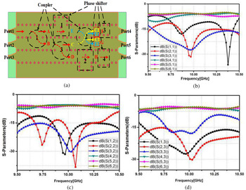
The Butler matrix can transform the incident signal to each output port with a certain power ratio, and a certain phase difference between the adjacent output ports. A novel Butler matrix based on SIW is proposed, as shown in Fig. 4. The structure is composed of three couplers and four phase shifters. With the arrangement of one 1.76 dB coupler located between two 3.0 dB couplers, the proposed Butler matrix can split the incident signal into three parts with the same amplitude. Phase shifters are used to adjust the phase difference. For example, when Port 1 is excited, the incident signal is split into two parts by Coupler 1. As shown in Fig. 4, the signal A can be labeled as a direct signal with a power level of −3.0 dB and signal B as a coupling signal. Then the signal B transmits into Coupler 3 (1.76 dB coupler) and is split into signal C and signal D. Thus, there are two input signals E and C for Coupler 2. The output signals F and G of Coupler 2 are composited of two parts, respectively. With the help of Phase shifter 1 and phase difference of couplers, the output signals F, G, and H have the same amplitudes. Phase shifters 2, 3, and 4 are applied to tune the phase of output signals, which leads a −120° phase difference. When antenna array is connected with these output ports, a beam away from the bore sight direction can be produced. A similar analysis can be done for the other two input ports.
S parameters of the proposed 3 × 3 Butler. (a) Structure. (b) Port 1, (c) Port 2, and (d) Port 3.

The proposed 3 × 3 Butler matrix based on SIW structure is designed and analyzed. The structure is simulated with HFSS v15, and the S parameters are shown in Fig. 4. It can be obtained that the return losses of three input ports at 10 GHz are <−15 dB. The output signals have equal level near −5 dB and the error <0.2 dB. The isolation between the input ports is >20 dB for three input ports.
When the different input ports are excited, respectively, the phase difference between the adjacent output ports is −120, 120, and 0°, respectively. The results of the phase difference between the output ports are shown in Fig. 5. As shown in Fig. 5(a), the phase differences of −120° at 10 GHz between two adjacent ports, Port 5 and Port 4, Port 6 and Port 5, can be obtained. Because of the narrow band property of SIW phase shifter, there is about 5° of error here. Similarly, when Port 2 and Port 3 are independently excited, the phase differences between the output ports is 120 and 0°, with a deviation of 6 and 3°, respectively. The results are shown in Figs 5(b) and 5(c).
Phase differences of output ports. (a) Port 1, (b) Port 2, (c) Port 3.

SIW slot antenna unit
The SIW is essentially a rigid structure that can shield electromagnetic fields, and conduct electromagnetic radiation by a slot on SIW. When the slot blocks the current on the waveguide, the electromagnetic field in the SIW acts as an excitation to the slot, and the electromagnetic wave is coupled to the free space through the gap. The gap is regarded as an impedance and an admittance element on the waveguide, as shown in Fig. 6. The gap fed by SIW can also be measured by its impedance or equivalent admittance in the circuit.
Phase differences in SIW slot antenna unit. (a) S parameter, (b) E-plane radiation pattern.

The SIW antenna unit is designed with the substrate Rogers 5880, as shown in Fig. 6(a). The unit is simulated and its results are shown in Fig. 6. We can notice that the return loss is <−20 dB at 10 GHz, and a directional radiation pattern is obtained. The corresponding parameter is Lt = 3.6 mm, Lt1 = 6 mm, Wt1 = 4.2 mm, Ws1 = 0.5 mm, and Ls1 = 16 mm.
Tri-beam antenna array
In order to realize three beams for antenna array, a 2 × 3 slot array is connected with the proposed 3 × 3 Butler matrix based on SIW structure, as shown in Fig. 7. The microstrip lines between the Butler matrix and the array can regulate the matching and improve the isolation between the ports to a certain extent. In order to avoid the interference among SMA connectors and feed the array conveniently, three microstrip line sections are added to the input ports of 3 × 3 Butler matrix.
Photograph of the proposed tri-beam antenna system.

The overall structure of the proposed tri-beam antenna system is simulated, optimized, and analyzed. As shown in Fig. 7, the overall length of the three-beam antenna array is L = 26.9 cm, and the width is W = 6.6 cm. The structure is designed with a one-layer substrate and includes radiation units, beamforming network, and microstrip section. Although the size of the proposed circuit is large for the working frequency, its tri-beam characteristic guarantees its application in practical wireless communication systems. The antenna overall size can be reduced if multi-layer substrate is adopted. When the different ports are excited, the distributions of electric field are shown in Fig. 8. The power of input signal is set as 1 W, and the phase is 0° when the distributions of electric field are plotted. It can be seen that the isolation between input ports is very good and the output signals of the 3 × 3 Butler matrix are at equal power distribution.
Distributions of the electric field for the tri-beam antenna system. (a) Port 1, (b) Port 3, (c) Port 2.

The measured results of the tri-beam antenna system are given in Fig. 9, from which we can notice that the return loss (S11, S22, S33) of each port is <−15 dB, and the isolation between ports is >30 dB at 10 GHz. Shown in Fig. 9(c), the response of S33 is in some way resonant. The reason is that the main transmission line for Port 3 is SIW structure including only phase shifter. Meanwhile, the additional microstrip section has some impact on the response. This performance can fully meet the requirements of practical application.
Measured S parameters of the fabricated structure. (a) Port 1, (b) Port 2, (c) Port 3.

The radiation performance of the proposed tri-beam antenna system is measured in a microwave anechoic chamber with far-field measurement method. The standard horn antenna is used to transmit the signal. As the antenna under test, the tri-beam antenna system can rotate around the axis and receive signal at the same time, as shown in Fig. 10(a). The directional radiation patterns at 10 GHz are shown in Fig. 10, when three input ports are excited, respectively. It can be seen from Fig. 10(b) that three beams with the directions of −30, 0, and 30° are obtained. The gain is measured by comparing with standard horn antenna as sample. The gain of each column antenna alone is about 6.5 dBi. Due to the loss of 0.8 dB of Butler matrix and the error of testing environment, the gain of the beam along 0° has a maximum gain of about 10 dBi. The H-plane patterns of tri-beam antenna system are symmetric along 0° axis. The proposed tri-beam antenna system produces a beam in the direction of 0°, which is a distinctive feature that is different from the conventional Butler matrix such as 4 × 4 or 8 × 8.
Measured radiation patterns. (a) Photograph of the testing environment, (b) E-plane, (c) H-plane.

Conclusion
A novel 3 × 3 Butler matrix based on SIW structure is proposed in this paper. With the help of SIW transmission line, SIW coupler, and SIW phase shifter, 3 × 3 Butler matrix can divide the electromagnetic signals into three output signals with the same amplitude and certain phase differences. The mechanism of the proposed structure is simulated, analyzed, and experimented. The return loss of <−15 dB and the isolation of >30 dB are obtained for the proposed Butler matrix. Two slots are cut off SIW transmission line and produce directional radiation. A 3 × 2 SIW slot antenna array is designed and connected with the proposed circuit. Three beams with the directions of −30, 0, and 30° are produced when different input ports are excited, respectively. This feature guarantees its potential application in the large beamforming antenna array.
Acknowledgements
This work is supported partly by Public Projects of Zhejiang Province under Grant No. 2017C31068, partly by 2016 Major Science and Technology Projects in Dongcheng District of Dongguan, partly by the Key Laboratory of millimeter wave program under Grant No. K201810, and partly by 2017 Major Science and Technology Projects in Dongguan under Grant No. 2018215105002.
 Zhenye Wang was born in Caoxian, Shandong, China. She received the Bachelor degree from Northeast Forestry University, Harbin, China, in 2006. She received the Master degree from Shaanxi Normal University, Xi'an, China, in 2011. From 2011 to 2015, she worked at Huisu Corporation as an antenna engineer. Now, she is working at Hangzhou Dianzi University, Hangzhou, China. Her research interests include computational electromagnetics and antenna array.
 Xiwang Dai was born in Caoxian, Shandong, China. He received the B.S. and M.S. degrees in electronic engineering from Xidian University, Xi'an, Shaanxi, China, in 2005 and 2008. He received the Ph.D. degree of electromagnetic fields and microwave technology at Xidian University in 2014. From March 2008 to August 2011, he worked at Guangdong Huisu Corporation as a manager of the antenna department. Now, he is working at the Hangzhou Dianzi University, Hangzhou, China. His current research interests involve metamaterials, omni-directional antenna, MIMO antenna, and low-profile antenna.
 Wen Sun was born in Yilan, Heilongjiang province, China. He received the B.S. degree in the School of Physical and Electrical Information Engineering from Daqing Normal University, Daqing, Heilongjiang, China, in 2013. He received the Master degree in the School of Electrical Information, Hangzhou Dianzi University, Hangzhou, Zhejiang Province in 2017. Now, he is pursuing the Doctor degree at Hangzhou Dianzi University. His research interests include antenna design, new material, and its medical applications.