Introduction
The rapid evolution of wireless communication systems increasingly requires the allocation of new frequency bands and therefore the design of new antennas with higher gains and wider bands. In the microwave frequency domain, microstrip and CPW technologies are usually used for low-power applications, when the waveguide technology is used for high-power applications. Microstrip and CPW devices require very strict tolerances for very small wavelengths, when the waveguide devices suffer from their very high manufacturing cost. The substrate-integrated waveguide (SIW) technology emerges as the transition between microstrips and waveguides. SIWs can be made by inserting metallic vias into the sidewalls of a dielectric-filled waveguide. In fact, the SIW inherits both microstrip techniques for compactness and ease of integration and the waveguide for low radiation losses [Reference Bozzi, Georgiadis and Wu1].
Over the last decade, SIW technology has been implemented in a variety of microwave circuits in passive and in active circuits. The proposed SIW passive circuits include filters [Reference Deslandes and Wu2], couplers [Reference Djerafi and Wu3], and antennas [Reference Yan, Hong, Hua, Hua, Chen, Wu and Cui4], where the active ones include oscillators [Reference Cassivi and Wu5, Reference Cao, Tang and Qian6], mixers [Reference Chen, Hong, Hao, Li and Wu7], and also active antennas [Reference Giuppi, Georgiadis, Bozzi, Collado and Perregrini8].
Other works propose what is called cavity-backed slot antennas which are based on SIW technology [Reference Luo, Hu, Dong and Sun9, Reference Bohórquez, Pedraza, Pinzon, Castiblanco, Pena and Guarnizo10]. This topology allows the design of antennas that target applications at high frequencies (X and Ku bands) [Reference Awida and Fathy11, Reference Kumar, Saravana and Raghavan12] and even in the field of millimeter-waves [Reference Cheng and Fan13]. More advanced cavity-backed slot antennas are proposed in [Reference Kumar, Dwari and Priya14, Reference Mukherjee and Biswas15].
Most cavity-backed single-slot antennas suffer of narrow bandwidth. The authors propose some solutions to confront this problem. Luo et al. propose to enhance the bandwidth of cavity-backed single-slot antenna by using hybrid SIW cavity modes [Reference Luo, Hu, Li, Zhang, Sun and Zheng16]. While Mbaye et al. propose a cavity-backed dual-slot with a bandwidth of 8.5% (0.8 GHz in the X-band) [Reference Mbaye, Hautcoeur, Talbi and Hettak17]. Mukherjee et al. suggest the use of a bow-tie slot to enhance the bandwidth more than 1 GHz (9.4%) [Reference Mukherjee, Biswas and Srivastava18]. Kumar and Raghavan present in [Reference Kumar and Raghavan19] a planer cavity-backed circular patch which gives more than 2.31 GHz (23.1%).
Another problem that suffers this type of antennas is the low values of gain. As an example, the antenna presented in [Reference Mukherjee, Biswas and Srivastava18, Reference Kumar and Raghavan19] which was presented as an antenna with a good bandwidth only allowed a gain of an average value of 3.7 dBi as the authors mentioned. Luo et al. proposed in [Reference Luo, Zhang, Dong, Li and Sun20] the use of high-order cavity resonance to enhance the gain of SIW cavity-backed slot antenna. The authors explain that, when the TE 220 resonance is excited in the SIW cavity, a high gain radiation is obtained (more than 8 dBi). Another version of this method proposes the use of a high-order cavity resonance to generate arbitrary levels of inclined linear polarization [Reference Bayderkhani, Forooraghi and Abbasi-Arand21].
In this paper, a broadband cavity-backed slot antenna with a high gain is presented. The main objective of this work is to design an antenna that gives a good compromise between a high gain and a large bandwidth. The novel structure proposed consists of a basic SIW topology in which three pairs of L-shaped resonators are placed on the bottom wall of the cavity (backed-slots): two of them having the same size (λ g/2 ) are used to enhance the gain, besides an additional small one in the middle that is added to expand the bandwidth. The effect of several geometrical parameters has been studied, and the final antenna makes it possible to have a stable gain of 9 dBi over the band 9.8 − 10.2 GHz.
Concerning the resonant frequency of the cavity, it is determined by its size. Thus, the radiation is generated by the TE140 resonance mode in this SIW cavity, and the lengths of the slots have notable effects on the operating frequency and the efficiency of the radiation. Indeed, the lengths of the slots must be close to λ g/2, and when the slot is in resonance, the energy can radiate to the maximum in space through the slots in order to obtain high radiation performance, including radiation efficiency and gain. The final antenna is realized on a Rogers RT/Duroid 5870 substrate. The gain, the reflection coefficient, and the radiation pattern are measured and compared to the EM simulation. The realized antenna presents a quasi-stable gain over the band 9.8 − 10.2 GHz, and the maximum value of 9 dBi.
Design procedure
To design a good SIW structure, it is necessary to specify the parameters needed for the design of the waveguide by respecting the conditions given by equations (1a and 1b) in order to fix the diameter d of the vias and the distance s between two adjacent vias [Reference Wu, Deslandes and Cassivi22].


The dimensions of the SIW-equivalent rectangular guide can then be derived using the following empirical equation (2).


where (W SIW, L SIW) and (W eq, L eq) are respectively the widths and lengths of the waveguide rectangular in SIW technology, and its equivalent waveguide.
The cut-off frequency for a solid rectangular dielectric-filled waveguide (RWG) is given by the following equations [Reference Pozar23]:


where a and b are, respectively, the width and the height of the waveguide; $f_{c_{mn}}$ represents the general cut-off frequency expression and $f_{c_{10}}$
 corresponds to the fundamental cut-off frequency mode.
The formulas given by equations (2) and (3) will be used to obtain the initial values of W eq and L eq, which will be optimized during the EM simulation to obtain the properties of the equivalent rectangular guide realized in SIW technology.
Figure 1 shows a cavity slot antenna based on SIW technology. This structure is based on a basic SIW topology in which L-shaped resonators are placed on the bottom wall of the cavity.
Proposed SIW cavity-backed L-shaped slot antenna geometry. (a) Top view, (b) bottom view.

Result and discussion
The proposed SIW antenna is designed in the ANSYS HFSS environment using a Rogers RT/Duroid 5870 substrate with a relative permittivity of ɛr = 2.33 and a thickness of 0.760 mm. In order to optimize the performance of the antenna, a parametric study on the number and the dimensions of the slots as well as on the feedline is performed. Below are the results of this study in detail.
Slots effect
The number of slots effect
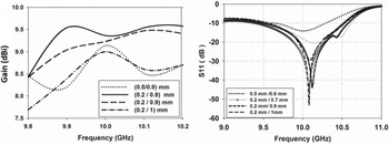
The initial structure is a basic SIW antenna structure without adding any slots. In order to study the effect of the slots on the SIW cavity-backed slot antenna, some slots are added. Likewise, a parametric simulation is performed to determine the number of slots that gives the optimal gain at the desired frequency band. Figure 2 shows the results obtained. It is sufficiently clear that the gain increases when more slots are inserted; the gain exceeds 9 dBi with three slots. In addition, the real and imaginary antenna impedance curves illustrated in Fig. 3 certify the positive effect of the addition of slots, on the bandwidth of the proposed antenna. In fact, the real part of the impedance Re (Z 11) is almost equal to 50 Ω on the operating antenna band [9.4–10.5 GHz]. As well as the imaginary part Im (Z 11) which is close to zero on this band.
The gain dependence according to the slot number. (a) With slot, (b) without slot.

Input impedance of the proposed antenna.

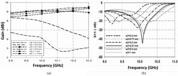
As for the width of the slots (Ws 1/Ws 2), it is small compared to the cavity wavelength and behaves like a capacity in series. This parameter generates only a small influence on the bandwidth and important influence on the gain. Figures 4(a) and 4(b) show the results obtained for a three-slot antenna. An optimal result is obtained for WS 1 = 0.8 mm and WS 2 = 0.2 mm.
Antenna performance in function of the slots width (W S1/W S1). (a) Gain variation, (b) S 11 variation.

Vertical slot position effect
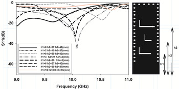
The authors have found that the variation of vertical position of slots gives a great influence on the bandwidth, so this parameter permits to widen the bandwidth as seen in Fig. 5.
Vertical slot position effect on the reflection coefficient of the proposed antenna SIW.

In the lower wall of the cavity, three radiating slot resonators with L-shaped form are graved. The excitation of these three pairs of slots is done by the feedline. The operating band of the cavity-backed slot antenna at 10 GHz is 9.4–10.5 GHz and the percentage bandwidth of the broadband is 11%.
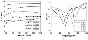
Among the variables with a great influence on the gain and the bandwidth are the length of the feedline L1, number of the slots (Fig. 2), and its positions (Fig. 5). Indeed, each slot has its own resonant frequency of the order of λ g/2 and can radiate in space at the maximum energy as soon as the three slots with optimal separation distances (h1, h2, and h3) are added. Consequently, the bandwidth and the gain are increased. Moreover, when the length of the feedline L1 is at an optimal value L1 = 47 mm (max gain) as shown in Fig. 7, both cavity resonance mode and slots are excited to increase the bandwidth, the gain, and radiation efficiency.
After all the parametric simulations and optimizations, the optimal physical dimensions are summarized in the following table (Table 1).
Optimal values of the antenna parameters

Feedline effect
The length of the feedline L1 allows to excite the resonance mode TE140 of the cavity and to excite the slots as well. So, it is better to adjust the resonance frequency of the slots in the desired X-band (TE 140 mode) in order to achieve high radiation performance, including efficiency and radiation gain. Indeed, a parametric simulation is performed to fix the optimal values of the feedline length L 1 and the parameter W 2, which have also an important influence on the gain as well as on the bandwidth. Figures 6 and 7 show the results obtained for three L-shaped slot antenna structures for different values of W 2 and L 1. An optimal result is obtained when W 2 is surrounding to 1 mm and the feedline length L 1 is approximately equal to 47 mm. We can notice that one of the keys of this structure is to play in the length of the feedline (L1), since this latter parameter has a great influence on the gain (we pass from 6 to 9.5 dBi) and also on the bandwidth (a bandwidth shift).
Antenna performance in function of W 2. (a) Gain variation, (b) S 11 variation.

Antenna performance in function of the feedline length (L 1). (a) Gain variation, (b) S 11 variation.

Results validation
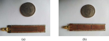
The final SIW antenna is made of copper. Its thickness is t m = 36 μm etched on a Rogers RT/Duroid 5870 substrate whose thickness is 0.760 mm and of a relative permittivity ɛr = 2.33 and a loss constant = 0.0013. A prototype antenna is made using the LPKF S63 machine with an accuracy of 0.05 mm. All perforated vias are filled with copper. Figure 8 shows a photograph of the fabricated prototype SIW antenna. The total area of this prototype antenna is about 64 × 14 mm2.
Photographs of fabricated SIW cavity-backed L-shaped slot antenna. (a) Top view, (b) bottom view.

The reflection coefficient S11 of the fabricated cavity slot antenna is measured using a ROHDE & SCHWARZ ZVB20 Vector Network Analyzer (VNA) which is available in the LASIT laboratory. This machine allows a measurement of the S parameters up to 20 GHz. Figure 9 shows the result measured in comparison with the result of the EM simulation. Good agreement is obtained between the measured and simulated results. Moreover, the reflection coefficient obtained by measurement shows a better adaptation to the central frequency of the band 9.5 − 10.5 GHz.
Reflection coefficient S 11 measured in comparison with the result obtained by simulation.

In addition, the variation of the gain over the band 9.8 − 10.3 GHz is measured and compared to the simulated gain (in CST and HFSS). Figure 10 shows that the gain and the efficiency of the radiation are reached, respectively, at 9 dBi and 96% at bandwidth.
Simulated and measured gain of the proposed antenna – radiation efficiency (%).

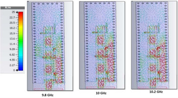
Figure 11 shows the surface current distribution of the proposed design at frequencies 9.8, 10, and 10.2 GHz. The current distribution at 9.8 GHz shows that only the first slot that resonates has a current maximum at the closed end of L-shape and current minimum at the left end of the slots. Likewise, the current distribution at 10 and 10.2 GHz shows that the three slots resonate and have a current maximum at the closed end of L-shape and current minimum at the left end of the slots.
The surface current distribution of the proposed design at 9.8, 10, and 10.2 GHz.

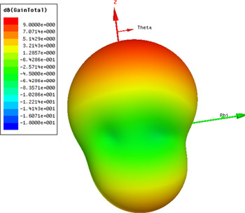
Finally, the simulation of the 3D radiation pattern of the antenna at the central frequency (10 GHz) is bidirectional as indicated in Fig. 12, whereas Fig. 13 shows the measured 2D radiation patterns obtained in the E- and H-planes at the frequencies 9.8, 10, and 10.2 GHz in comparison with the 2D radiation patterns obtained from the EM simulation. The measured co-polarization and cross-polarization models are similar to simulated one. It can be seen from the radiation profile of the proposed antenna that it has the characteristics of bidirectional radiation (−5 dB in back radiation compared to the main lobe), where the side lobe levels of the radiation patterns are less than −13, −20, and −15 dB at the frequencies 9.8, 10, and 10.2 GHz.
Simulation 3D radiation pattern at the resonance frequency of cavity slot antenna.

Simulated and measured radiation patterns of the proposed antenna at 9.8, 10, and 10.2 GHz.

However, there is a slight difference in the simulated and measured cross-polarization of the frequencies 9.8 and 10.2 GHz data which can be considered due to manufacturing imperfections or welding errors. Also, the measured cross-polarization levels in H-plane at the frequencies of 9.8, 10 and 10.2 GHz are below −23, −19, and −16 dB, respectively, and these values in E-plane are below −24, −20, and −19 dB, respectively.
The gain and the radiation pattern measurements are realized using the “Antenna Measurement Systems” of Geozondas Ltd which allows to measure different antenna characteristics (Antenna Pattern, Gain) in the wide frequency range: from 0.1 to 40 GHz. Operation of all systems is based on pulse (Time Domain, TD) measurements. This method has some advantages over traditional Frequency Domain (FD) techniques since it does not require expensive anechoic chamber. Multiple parasitic reflections from walls, ceiling, and other objects can be simply eliminated with appropriate selection of Delay and Time Window width for measurement [24, Reference Levitas, Drozdov, Naidionova, Jefremov, Malyshev and Chizh25].
The slight difference observed between the measurement and simulation of S11 as shown in Fig. 9 is due to the influence of solder SMA conductor on the antenna, the characterization of the substrate, the loss measurement cable test as well as the precision of the LPKF machine. The gain measured is slightly lower than the simulated one, this is due to the loss measurement.
Table 2 illustrates the comparison between different SIW antenna structures, including size, bandwidth, gain in bandwidth, and cross-polarization level. The results confirm the superiority of the performance of our design.
A comparison between proposed antenna and the state-of-art works

Conclusion
In the present paper, a SIW cavity slot antenna structure has been designed and a prototype has been fabricated on a Rogers RT/Duroid 5870 substrate. The antenna operates in a band of 9.4–10.5 GHz with a bandwidth of 11%, which makes it very suitable for X-band applications. The measured gain reaches a value of 9 dBi, which can be considered as a very high gain compared to the size of the antenna. The proposed cavity-backed L-shaped slot antenna gives a good compromise between a high gain and a large bandwidth.
 Dahbi El khamlichi was born in Tetouan, Morocco, in 1984. He received his License degree in 2013. He obtained his Master's degree in Electronics and Telecommunications in 2015 from the Abdelmalek Essaadi University Tetouan, Morocco. He follows his research in the laboratory of information systems and telecommunications. He is currently pursuing his Ph.D. research in the field of optimization of passive microwave structures using the particle swarm optimization (PSO) algorithms.
 Naima Amar Touhami received DESA in Instrumentation and Electronics and Ph.D. degree in Electronics and Telecommunication from the University of Abdelmalek Essaadi in 2002 and 2009, respectively. She received the AECID scholarship from the Spanish Ministry of Foreign Affairs (2005–2008) and participated in several research projects. She is an Associate Professor of electronics and telecommunications at the University of Abdelmalek Essaadi and a member of EIRT. She has supervised Master's and Bachelor's degree students. She has more than 40 journal papers and 40 conference papers. She has participated in the organization of some conferences and events for Ph.D. students. Her research interests include synthesis of advanced high-performance active and passive circuits such as antennas, filters, diplexer, amplifier, and mixer.
 Tajeddin Elhamadi was born in Alhoceima, Morocco, in 1982. He obtained his Master degree's in Electronics and Telecommunications in 2013 from Abdelmalek Essaadi University. In 2017, he obtained his Ph.D. degree in Physics from Abdelmalek Essaadi University, Tetouan, Morocco. Currently, Elhamadi is a researcher at the Faculty of Sciences at Abdelmalek Essaadi University. He directs his research in the information systems and telecommunications laboratory. His research work focuses on the characterization and modeling of microwave devices using neural networks, as well as the design of microwave circuits in GaAs and GaN MMIC technology. His research interests also include the optimization of planar circuits using evolutionary algorithms. In particular, the optimization of planar antennas by the genetic algorithm and the particle swarm optimization algorithm (PSO). Recently, he was introduced to the field of artificial intelligence and machine learning and their applications in the field of robotics and self-driving.
 Mohammed Ali Ennasar was born in Tetouan, Morocco. He received the Ph.D. degree in Electrical Engineering from Mohamed V University Rabat, Morocco and the Master's degree in Electronics and Telecommunication from Abdelmalek Essaadi University, Morocco, in 2020 and 2013, respectively. In 2015, he joined the Information and Telecommunication Laboratory, Abdelmalek Essaadi University, Tetouan, Morocco, under a grant number PPR2/2015/36 project, which was supported by the Moroccan Ministry of Higher Education (MESRSFC) and the CNRST of Morocco, in 2016. He was a Researcher under scholarship Erasmus+ with the Higher Technical School of Telecommunication Engineering, Polytechnic of Cartagena University, Spain, as a part of his doctoral research. His current research interests include wideband antennas, RFID-Tag antennas sensors, flexible printed electronics, passive sensing, and body-centric antennas.